Rebuilding a 2½" Gauge LBSC Green Arrow
Mar 6, 2021 0:54:22 GMT
RGR 60130, uuu, and 9 more like this
Post by John Baguley on Mar 6, 2021 0:54:22 GMT
Part 10 - Time to finish the inside valve
As hinted at earlier, I had decided to change the way that the inside valve was driven. LBSC's method was to cut a narrow slot across the valve and file flats on either side of the valve spindle so the spindle fits the valve slot snugly and the ends of the flats drive the valve. It was a common method used by him but I don't like it at all. The area driving the valve is very small and can lead to rapid wear. Having said that, the valves on Ayesha are driven like that and still seem ok so maybe I'm overthinking it.
The main think I didn't like with this design was that there was no means to adjust the valve. LBSC suggests moving the wheels on the driving axle to get the timing right for the inside cylinder which sounds a dreadful idea to me! It would have been possible to make the fork on the end of the rod adjustable but I chose to use a threaded valve spindle driving a threaded nut so the valve can be adjusted by rotating the valve spindle.
The valve was machined just the same as the outside ones but the driving nut was threaded 5BA instead of being held by grub screws.

The valve spindle was also modified to have a threaded section.


Because I had added the threaded section to the valve spindle I reduced the end to produce a parallel surface to run in the rear boss. If I had left it threaded it would not be a very good bearing surface. This meant that the 1/8" hole that I had reamed in the rear boss was now too big so I drilled it out and tapped it 1/4" x 40 and made a bronze boss which screwed in and had a smaller hole in it.


I couldn't resist a trial assembly of the cylinders complete with valves.

I then realised that I still hadn't drilled the exhaust passage in the inside cylinder so that was the next job. This was done in a similar way to those for the outside cylinders - drill a hole so far in from the top of the cylinder and then another at an angle from the exhaust port to join up.


I've also still got to drill the steam inlet to the inside valve chest but I'll do that when we get to the steam and exhaust manifolds.
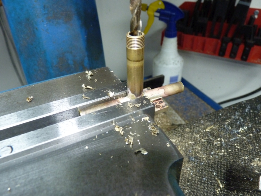
The crossheads were not yet secured to the piston rods so onto that job. I removed the pistons from the cylinders, pushed in the piston rods to the crossheads which were a reasonably tight fit and then held the piston rods in the mill whilst I drilled the holes for the taper pins.
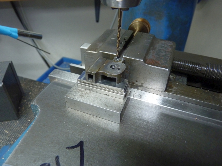
The crossheads already had holes for the pins drilled so it was just a case of lining up the drill with the existing hole and then drilling through the piston rod. The holes were then reamed with a taper reamer to take new taper pins.
The original gudgeon pins were a real pain to fit as they had to be fitted from the back and screwed into the drop arm on the outside. The builder must have decided to do it this way as the drawings show the pins passing through the drop arms and secured by a nut on the outside. Needless to say, the heads of the pins were a bit chewed up where pliers had been used to screw them in. Putting a nut on the outside made them a lot easier to fit so I made new ones from silver steel with a longer shank and drilled out the drop arms so the pins just pushed through.

It was now time to start messing with the valve gear so I reassembled the cylinders, connecting rods and valve gear. It was obvious that there was play in various bits of the valve gear that would lead to lost motion. The bushes in the motion brackets for the expansion link trunnions were quite sloppy so I made new ones. One of the combination lever pins was a loose fit but i just replaced it with a suitable drill for the time being! I'll make a new pin later.
I also found that the motion had become quite stiff since I made the new crosshead pins (which were a better fit than the old ones) and it turns out one of the connecting rods was bent so needed straightening.
One of the things I wanted to check was the valve travel in mid gear. The calculated valve travel should be 0.117" which is interesting as that gives the valves a negative lead of -0.004" if they are made to the dimensions on the drawings. I don't think that is intentional as LBSC was a big fan of lead on his locos and I can't see him deliberately doing that. I'm going to change that by reducing the lap of the valves to give a positive lead of 0.005", my thinking being that the slight positive lead will cater for any eventual wear and any lost motion in the valve gear.
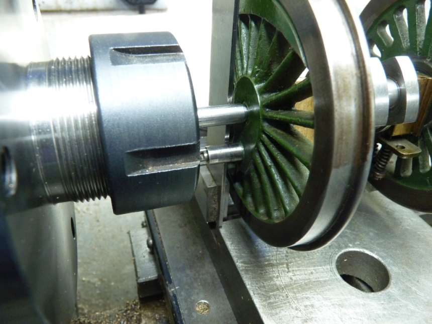
I faffed around for ages trying to measure the valve travel with calipers but it was difficult to get any consistent results. Then I thought 'you've got a drawer full of dial gauges - use one of those!
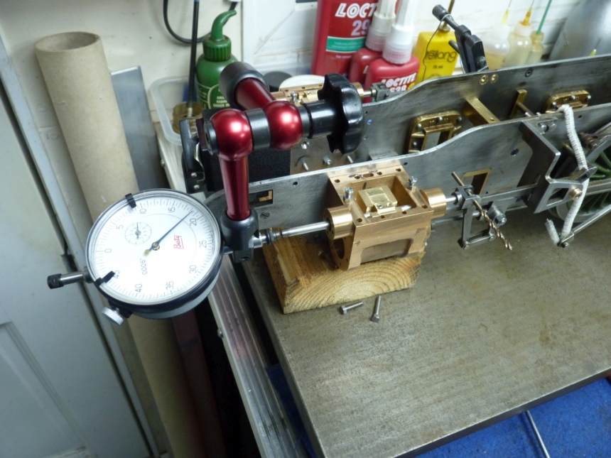
That was much easier with the gauge on the ends of the valve spindles.
I was rather surprised that the results came out much better than I expected. The lefthand side gave 0.118" travel and the righthand side gave 0.113". The difference is probably due to slight differences in the lengths of the combination levers. I can live with that. I'm not making new combination levers.
I then measured the valve travel in full forward gear. The lefthand side gave 0.258" but the righthand side gave only 0.230" That could be due to the return cranks not being set exactly the same but the righthand die block seemed to be loose in the expansion link slot which would cause some lost motion.
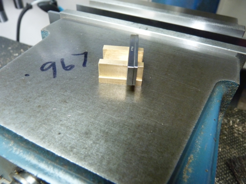
I did some quick calculations using a spreadsheet that I designed for this purpose and if I reduce the lap of the valves from 0.0625" to 0.054" that will give a lead of 0.0045". The valve travel in full gear to give a cut off of 76% is 0.22" so we are about in the ballpark already. The ports will open by 0.056" which is just about halfway. That doesn't seem a lot but I think that's right. It's not how far the ports open it's the length of time that they are open for that matters.
I had a look at the loose die block and it was the screw that it pivots on that was a loose fit in the block rather then the die block being a loose fit in the expansion link slot. I just made a new one from silver steel.

The screws just thread into the radius rods so I made the new screw a bit longer so that it can have a locknut fitted on the other side to make sure it can't come undone. I think they should have been done like that anyway. I'll replace the screw on the other side when I finally reassemble everything.
Whilst doing all this I noticed that the radius rods were hard up against the side of the slots in the motion brackets so I took the brackets off and milled the slots wider to give some clearance.

The motion seemed a lot freer after doing that.
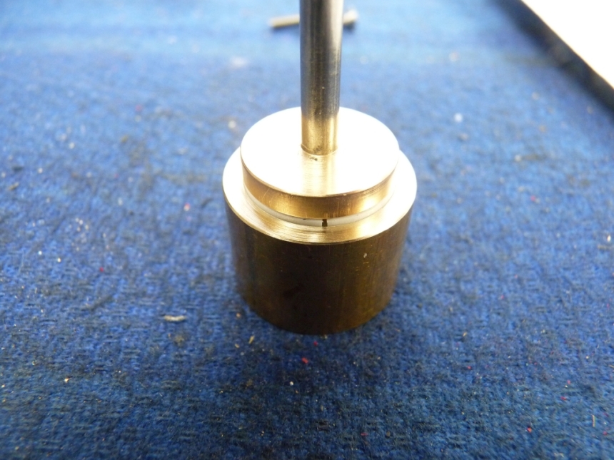
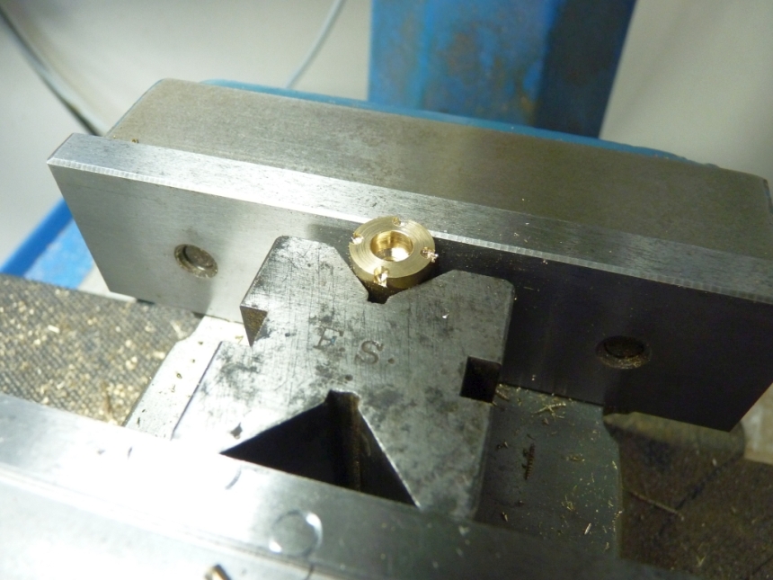
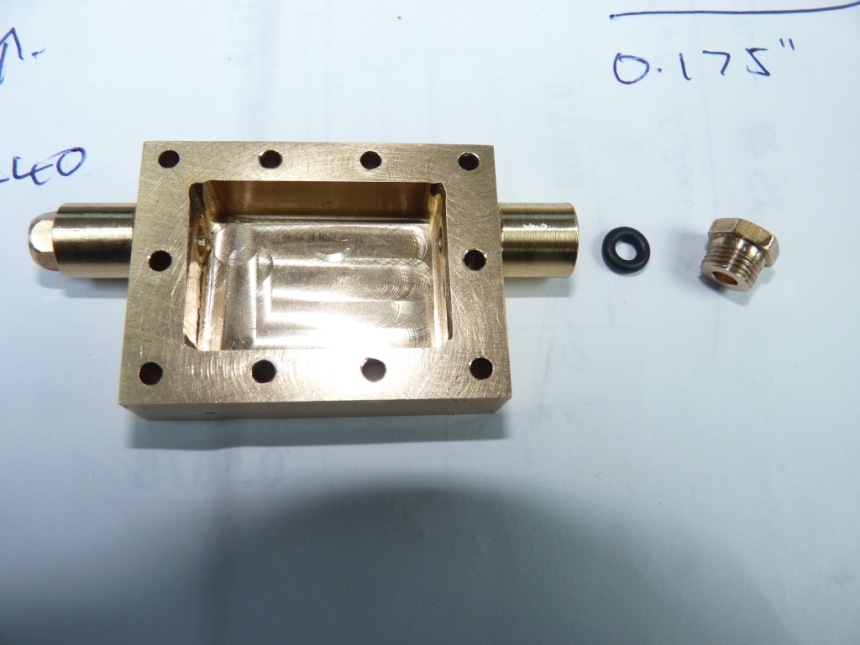
One job that still needed doing was to make the O ring retaining caps for the bosses on the valve chests. These were a simple turning job from brass bar.

The fixing holes were drilled with the DRO in the mill. I made a simple jig for this that the covers were held to with a bolt through the valve spindle hole.

The inside valve chest still needed a threaded gland nut to retain the O ring seal for the valve spindle. That was turned from hexagon brass bar.
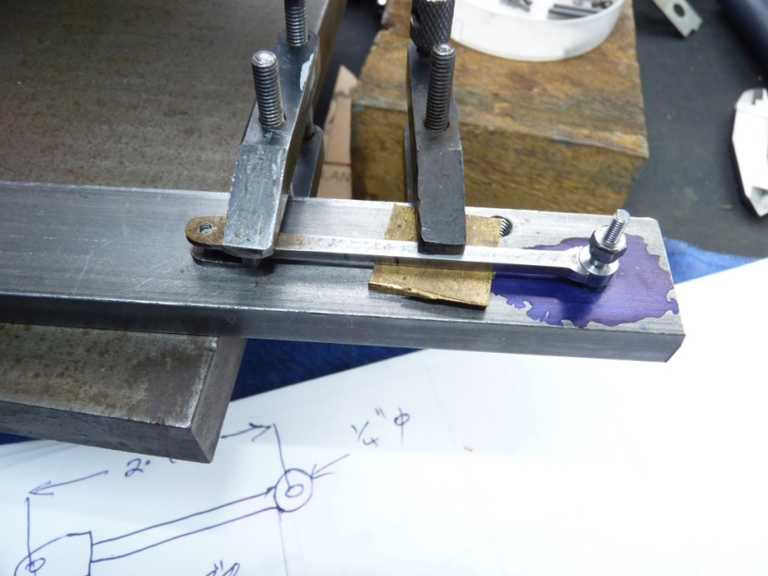
The outside valve spindles had been left long so now was the time to trim them to length and thread the front ends for the forks for the links that connect to the 2 to 1 levers.

I hadn't yet worked out a plan to secure the pin on the inside end of the short lever but as it happens it can't fall out anyway as it always remains inside the outside edges of the long lever so it can be left floating. Problem solved!
We are not that far of running the chassis on air now but first we need the steam and exhaust manifolds and the piston rings. Oh, and trim the valves to length. More of that next time.
John
As hinted at earlier, I had decided to change the way that the inside valve was driven. LBSC's method was to cut a narrow slot across the valve and file flats on either side of the valve spindle so the spindle fits the valve slot snugly and the ends of the flats drive the valve. It was a common method used by him but I don't like it at all. The area driving the valve is very small and can lead to rapid wear. Having said that, the valves on Ayesha are driven like that and still seem ok so maybe I'm overthinking it.
The main think I didn't like with this design was that there was no means to adjust the valve. LBSC suggests moving the wheels on the driving axle to get the timing right for the inside cylinder which sounds a dreadful idea to me! It would have been possible to make the fork on the end of the rod adjustable but I chose to use a threaded valve spindle driving a threaded nut so the valve can be adjusted by rotating the valve spindle.
The valve was machined just the same as the outside ones but the driving nut was threaded 5BA instead of being held by grub screws.

The valve spindle was also modified to have a threaded section.


Because I had added the threaded section to the valve spindle I reduced the end to produce a parallel surface to run in the rear boss. If I had left it threaded it would not be a very good bearing surface. This meant that the 1/8" hole that I had reamed in the rear boss was now too big so I drilled it out and tapped it 1/4" x 40 and made a bronze boss which screwed in and had a smaller hole in it.


I couldn't resist a trial assembly of the cylinders complete with valves.

I then realised that I still hadn't drilled the exhaust passage in the inside cylinder so that was the next job. This was done in a similar way to those for the outside cylinders - drill a hole so far in from the top of the cylinder and then another at an angle from the exhaust port to join up.


I've also still got to drill the steam inlet to the inside valve chest but I'll do that when we get to the steam and exhaust manifolds.
The crossheads were not yet secured to the piston rods so onto that job. I removed the pistons from the cylinders, pushed in the piston rods to the crossheads which were a reasonably tight fit and then held the piston rods in the mill whilst I drilled the holes for the taper pins.

The crossheads already had holes for the pins drilled so it was just a case of lining up the drill with the existing hole and then drilling through the piston rod. The holes were then reamed with a taper reamer to take new taper pins.
The original gudgeon pins were a real pain to fit as they had to be fitted from the back and screwed into the drop arm on the outside. The builder must have decided to do it this way as the drawings show the pins passing through the drop arms and secured by a nut on the outside. Needless to say, the heads of the pins were a bit chewed up where pliers had been used to screw them in. Putting a nut on the outside made them a lot easier to fit so I made new ones from silver steel with a longer shank and drilled out the drop arms so the pins just pushed through.

It was now time to start messing with the valve gear so I reassembled the cylinders, connecting rods and valve gear. It was obvious that there was play in various bits of the valve gear that would lead to lost motion. The bushes in the motion brackets for the expansion link trunnions were quite sloppy so I made new ones. One of the combination lever pins was a loose fit but i just replaced it with a suitable drill for the time being! I'll make a new pin later.
I also found that the motion had become quite stiff since I made the new crosshead pins (which were a better fit than the old ones) and it turns out one of the connecting rods was bent so needed straightening.
One of the things I wanted to check was the valve travel in mid gear. The calculated valve travel should be 0.117" which is interesting as that gives the valves a negative lead of -0.004" if they are made to the dimensions on the drawings. I don't think that is intentional as LBSC was a big fan of lead on his locos and I can't see him deliberately doing that. I'm going to change that by reducing the lap of the valves to give a positive lead of 0.005", my thinking being that the slight positive lead will cater for any eventual wear and any lost motion in the valve gear.
I faffed around for ages trying to measure the valve travel with calipers but it was difficult to get any consistent results. Then I thought 'you've got a drawer full of dial gauges - use one of those!

That was much easier with the gauge on the ends of the valve spindles.
I was rather surprised that the results came out much better than I expected. The lefthand side gave 0.118" travel and the righthand side gave 0.113". The difference is probably due to slight differences in the lengths of the combination levers. I can live with that. I'm not making new combination levers.
I then measured the valve travel in full forward gear. The lefthand side gave 0.258" but the righthand side gave only 0.230" That could be due to the return cranks not being set exactly the same but the righthand die block seemed to be loose in the expansion link slot which would cause some lost motion.
I did some quick calculations using a spreadsheet that I designed for this purpose and if I reduce the lap of the valves from 0.0625" to 0.054" that will give a lead of 0.0045". The valve travel in full gear to give a cut off of 76% is 0.22" so we are about in the ballpark already. The ports will open by 0.056" which is just about halfway. That doesn't seem a lot but I think that's right. It's not how far the ports open it's the length of time that they are open for that matters.
I had a look at the loose die block and it was the screw that it pivots on that was a loose fit in the block rather then the die block being a loose fit in the expansion link slot. I just made a new one from silver steel.

The screws just thread into the radius rods so I made the new screw a bit longer so that it can have a locknut fitted on the other side to make sure it can't come undone. I think they should have been done like that anyway. I'll replace the screw on the other side when I finally reassemble everything.
After fitting the new screw I checked the full gear travel again and both sides were the same at 0.230". A bit different to the last result but the reverser is not a very rigid fit to the frames at the moment and tends to move backwards and forwards. It looks like the return cranks are both set spot on and the valve travel is pretty much what it should be. Good news 

Whilst doing all this I noticed that the radius rods were hard up against the side of the slots in the motion brackets so I took the brackets off and milled the slots wider to give some clearance.

The motion seemed a lot freer after doing that.
One job that still needed doing was to make the O ring retaining caps for the bosses on the valve chests. These were a simple turning job from brass bar.

The fixing holes were drilled with the DRO in the mill. I made a simple jig for this that the covers were held to with a bolt through the valve spindle hole.


The inside valve chest still needed a threaded gland nut to retain the O ring seal for the valve spindle. That was turned from hexagon brass bar.

The outside valve spindles had been left long so now was the time to trim them to length and thread the front ends for the forks for the links that connect to the 2 to 1 levers.

I hadn't yet worked out a plan to secure the pin on the inside end of the short lever but as it happens it can't fall out anyway as it always remains inside the outside edges of the long lever so it can be left floating. Problem solved!
We are not that far of running the chassis on air now but first we need the steam and exhaust manifolds and the piston rings. Oh, and trim the valves to length. More of that next time.
John


