|
|
Post by firebox on Mar 29, 2017 12:38:31 GMT
Looking good Jim!
|
|
|
|
Post by Geoff (Carlisle) on Mar 29, 2017 21:39:35 GMT
Hi Jim, it's quite a while ago but when I was ready to bend my tender sides with the bending jig I made. It was 16g brass and I couldn't make any impression on it. So I got my next door neighbour , who is a body builder to do the job for me and he did with ease . I remember him saying 'you stand like this with your legs apart' and pull, to him it was easy .
Geoff (Carlisle).
|
|
|
|
Post by Jim on Mar 29, 2017 21:51:08 GMT
Thanks for the heads up Geoff. I've just checked out my neighbours and they're all doddery old blokes like me, on the other hand my son is a strapping young bloke so I might start buttering him up.  Jim |
|
|
|
Post by Jim on Apr 1, 2017 4:19:04 GMT
We're slowly getting there as the side walls are added to the access way into the bunker, they also act as strengthening spacers between the front and rear plates.  Once the plate had been washed to remove any trace of flux the front section was placed in position and held in place to stop it moving, springing, slipping or any other way of getting out of position while being soldered. Of course it did move which makes me think Model engineers should have 4 hands on extendible arms and at least one of the hands should be heat proof👀😃  The front removable section is now complete with just various details to add such as hinges, locking bars etc. The doors on BR tenders should be flush but I've made the doors proud so as they are part of the locating slots that allow the front panel to be replaced at the end of a day's running. That day is slowly approaching too.  Jim |
|
|
|
Post by 92220 on Apr 3, 2017 13:32:46 GMT
Hi Jim
I've just received the drawings for the Afloc Water treatment equipment. I think that Hornby tender is wrong to have 2 manhole covers.
The drawings are very 'sketchy' and I need to go through them and make a working drawing so that the parts can be made. When I've done that I'll post it for everyone building a late B1G tender.
Bob
|
|
|
|
Post by Jim on Apr 5, 2017 6:11:35 GMT
At last some of the details such hinges and locking bars for doors have been added. As mentioned earlier there are a lot of variations between the drawings of the tender fronts on one hand and the photos of the actual thing. In the end I have selected the features I like such as the use of locking bars with central pivots rather than those with off set pivots. Other variations include the sliding bolt for the side locker or a hasp and staple for the top locker both of which variations appear in drawings. This photo from Clarke's book shows the only photo I've of the front of a BR 1 tender. It shows bolts for both the top and side lockers.  Finally, the lift out section in place.  Jim (slowly going nuts) |
|
|
|
Post by Cro on Apr 5, 2017 6:21:29 GMT
Looking good Jim, Will try get a photo of the one I did on the 9f a long time ago! I ended up with opening doors and the locking bars but I have no idea what will have when I paint it as open it once and all the paint will come off! I may need to take the bar off and put a small spacer under it and adjust the latches.
Adam
|
|
|
|
Post by Jim on Apr 5, 2017 6:28:23 GMT
I'm a bit amazed at how the various drawings have quite different features compared to Clarke's photos or some partial photos on JJ's site. The Bi fold doors on the access way to the bunker was a stretch too far for me I'm afraid. Anyway I'd never fit through the opening.  Look forward to seeing the photo of the 9F's tender front. Jim. |
|
|
|
Post by Cro on Apr 5, 2017 6:36:56 GMT
The only one I didn't hinge, which I still may do is the one above the water scoop handle, drivers side. But Dad had a great suggestion after seeing a lovely Black 5 that was RC controlled that I fit a radio gear in the removable section, a servo in the drivers side locker and control the regulator with it and a small camera in the top locker to watch the water gauges! Now that is real GL5!!
Adam
|
|
|
|
Post by springcrocus on Apr 5, 2017 6:38:55 GMT
Jim, thanks for showing that photo of the front of the BR1 tender. I have spent hours trawling the internet trying to find a picture and have been using the Hornby model as a guide. The locker doors are different to the BR1G and your photo shows it well. I should probably have PM'd you before and asked for guidance but you know how it is. We all like to do our own thing if we can. I think I might just cut and paste a photo of your tender front onto my brasswork, save myself some work and no-one will ever know.  Regards, Steve Edit. I've just noticed - no water-scoop handle! Oh, the confusion... |
|
|
|
Post by Jim on Apr 5, 2017 7:13:27 GMT
I must admit Steve I thought I'd got away with not having a water scoop handle when I saw that photo, that is until Stan pointed out the the GE did in fact have water troughs. Now I'll have to make provision for the scoop handle.  I will say the wider opening makes access to the cab much easier. Jim. |
|
|
|
Post by Jim on Apr 8, 2017 7:44:58 GMT
I spent a bit of time today going through various books trying to find details of the 'weather strip' on the rear of the tender canopy. JP shows it as a curved angle strip riveted to the top of the canopy in the same way as the one on at the rear of the cab roof. I wasn't convinced that that was correct as any of the photos I'd seen didn't show it as a riveted angle strip and my other drawings just didn't feature it at all. Anyway I found this photo in Clarke's book on the Standard Pacifics which gives a pretty clear view of the back of the canopy and the plate that forms the weather strip along with an angled strip along the bottom edge of the plate. I must say other photos show a variation of this as a flat narrow curved strip. 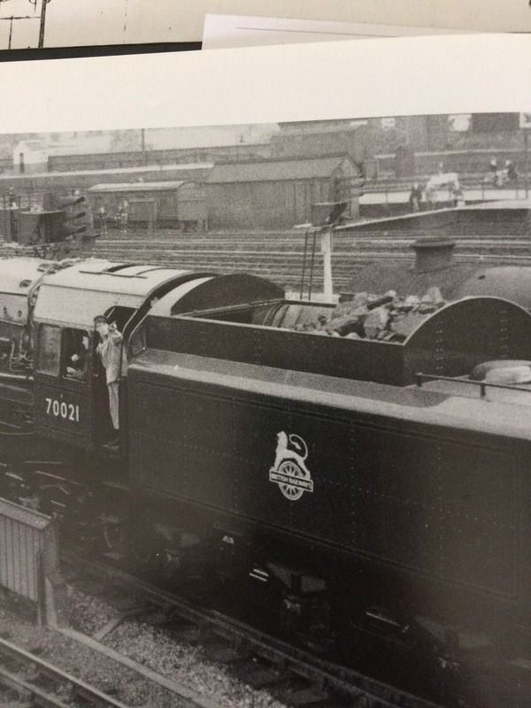 This photo which was the right way round shows the narrow curved strip. 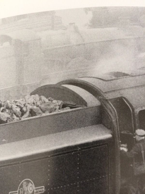 As the next photo shows this is the version I opted for, it was the easier to make  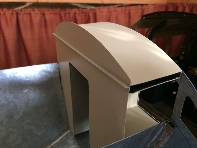 For anyone interested I gave the lift out section a coat of grey etch primer then when cured a coat of filler primer to fill any scratches or file marks. I find this combination works well for me. Finally just for interests sake these are the two products I used. I'm sure similar products are available overseas in auto parts shops such as Halfords. 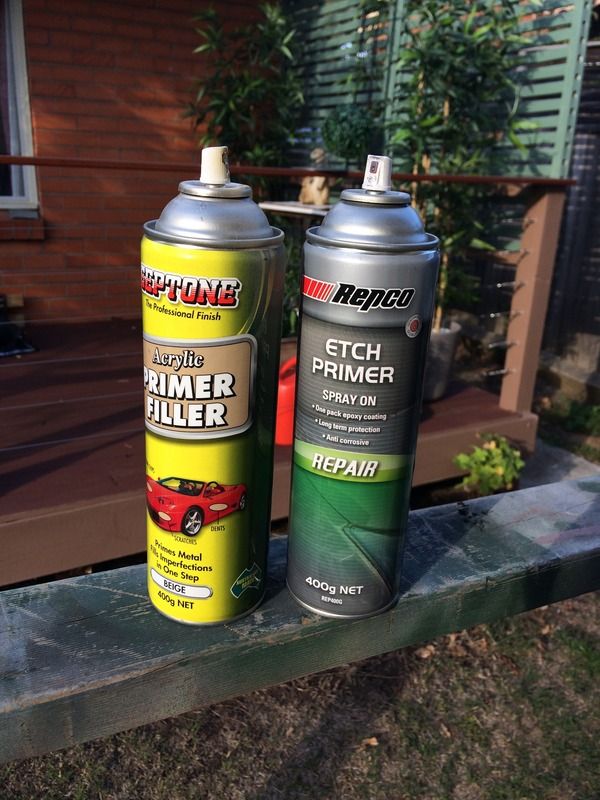 . It's interesting I think in looking at Steve's (Springcrocus) approach to his Britannia's tender to see that there is more than one way of tackling the same task. I might add as a result of Steve's work I've decided to redo a couple baulkheads in 1mm steel. Despite being the nation's capital brass sheet is as scarce as hen's teeth here and I don't fancy a 600km round trip to the one supplier I know of in Sydney. Jim. |
|
|
|
Post by 92220 on Apr 9, 2017 16:42:24 GMT
Hi Jim.
I've taken a couple of scans off the original B.R. Tender Tank Arrangement for the B1G tender. Hopefully they will clarify the set-up on that curved top. Please excuse the colour of the prints. In the very early days of my build, I borrowed a number of drawings from the Science Museum, in London to copy on the big dyeline printer that we had in the drawing office where I worked, so my drawings are a copy of a print.
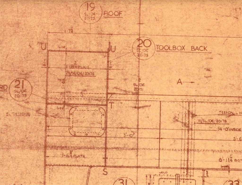
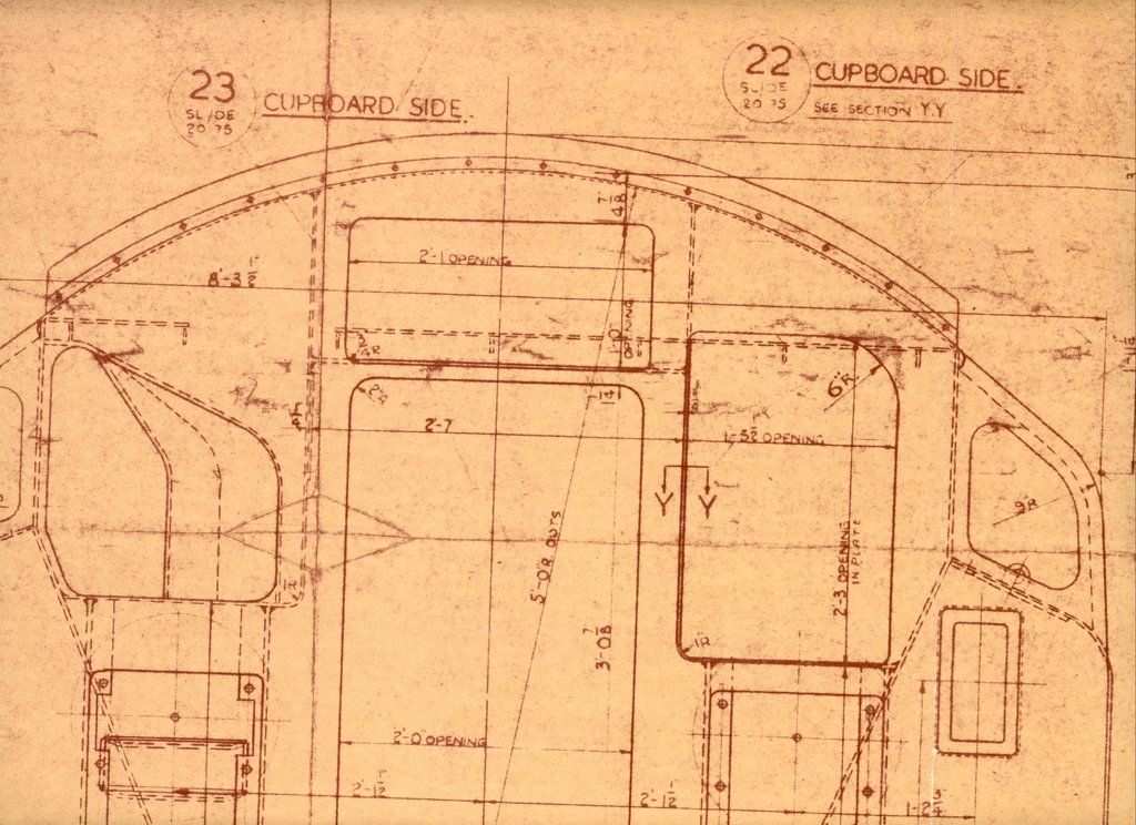
Hope they help.
Bob
Edit: I forgot to say, the curved top at the back, is a curved strip, riveted to the upstand which is the rear panel of the toolbox. The upstand, if you want to simulate it, is 1" fullsize, so 0.0885" scale (0.09") |
|
itchyballs
Active Member
  trying to figure out why
Posts: 29 
|
Post by itchyballs on Apr 9, 2017 17:53:37 GMT
Jim any metal suppliers in sydney would send to you a full sheet of brass via courier. You could of course try a new approach and buy the stuff from the local model engineering suppliers. If we want to have the suppliers and castings available in Australia we should always support the local blokes before we go overseas to buy our parts overseas. Unless we all support the locals we will all be buying from uk or us suppliers and with our dollar and freight that will cost us a fortune.
|
|
|
|
Post by Jim on Apr 9, 2017 22:03:38 GMT
Thanks for posting those drawings from the BR1G tender, they are very helpful indeed and just the detail I was looking for, many thanks Bob.
It's funny isn't it that when those tenders were drawn, built and crewed by countless drivers and firemen none could have ever imagined anyone being even slightly interested in the strip of metal around the top of the tender's canopy. It's finding details like that that make the hobby so interesting..well for me it is.
Thanks again
Jim
|
|
|
|
Post by Jim on Apr 11, 2017 9:57:00 GMT
As a follow on from Bob's post I've gone through Richard Derry's book on the Britannias which is a great source of information on the class.. According to Derry the 9Fs had the BR1G tenders shown in Bob's post while the Britannias up to 70044 had BR1 tenders and the remainder 70045 to 70055 had BR1Ds. I've added Derry's list of Britannias and their tenders for the information of other interested Britannia builders. Jim   |
|
|
|
Post by Jim on Apr 14, 2017 22:36:53 GMT
On Steve's, 5" Britannia Build Diary there was a discussion about using countersunk rivets in the area where the BR logo went on the tender sides. I suspect the issue depended on where the locomotive was based as other photos I've found show the same area with rivets. (see the two photos posted previously) While you can buy products that soften the transfers to settle over things like rivets you can appreciate my relief to find this unsourced photo of 70036 in what appears to be relatively clean condition and with countersunk or as Steve suggests, rivet heads ground off where the logo is. 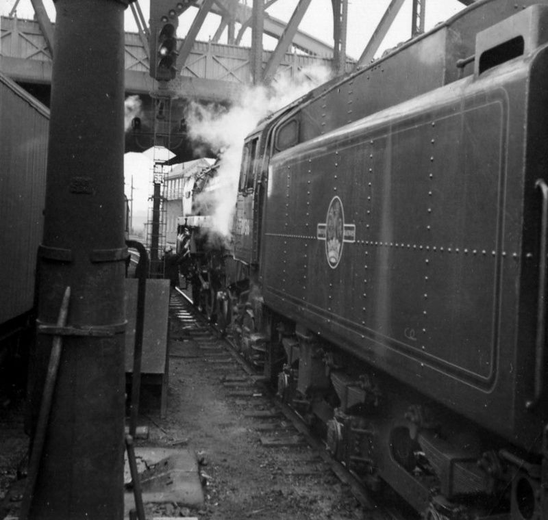 That's a few less holes to drill.  Jim. |
|
|
|
Post by Jim on Apr 15, 2017 1:41:23 GMT
Just found a note saying the above photo was taken at Crewe in 1966. The photo also shows how the lining skirts as far as possible the rivet heads.
Jim.
CORRECTION. Just had an Email from Stan to say this photo wast taken in 1962 at Peterborough where 70036 was taking on water the early Cleethorpes to Kings X
My apologies Stan for the mix up.
|
|
pclass
Active Member
 
Posts: 29 
|
Post by pclass on Apr 15, 2017 7:47:58 GMT
Nice work Jim, I have been following your posts, and checking in here this evening has answered a question for me, you must be at home and not the Convention, I was keeping an eye out for you, I met up with Shawki S, anyway sorry to hi jack your thread, cheers Dennis
|
|
|
|
Post by Jim on Apr 15, 2017 7:58:13 GMT
Hi Dennis, Yes I'm at home and sorry I missed you though good friend Dave Proctor from Canberra was at the AALS convention he being the President and all or should I say was?  I think his term had come to an end. Dave and I along with three other modelers meet up for lunch every Thursday, very convivial I must say. How's your project coming along? Jim. |
|