|
|
Post by Jim on May 28, 2012 11:50:01 GMT
Please, please Pete don't mention costs. If SWOMBO found out what the copper cost I could well be in need of more than a restorative ale...or two.  |
|
peteh
Statesman
  Still making mistakes!
Posts: 760
|
Post by peteh on May 28, 2012 23:47:19 GMT
;D
|
|
|
|
Post by Jim on May 29, 2012 4:22:46 GMT
This morning I decided to continue and cut out the hole for the fire hole ring in the fire box door plate. Finding the correct location was made easy by the fact that I'd prevously drilled a 2.5mm hole through the proposed fire hole center in the back head. In a temporary set up of the plates and wrapper a transfer punch was used to lighly mark the centre on the fire box door plate. It's has all worked out nicely..quite amazing really.  I must say the 2 sets of transfer punches (metric and imperial) are rather handy for all sorts of tasks besides their intended ones. The photo shows the fire hole ring in location in a trial set up to check that all fits together. 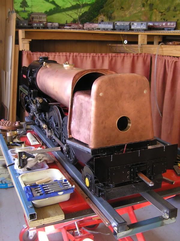 Jim |
|
jma1009
Elder Statesman
  
Posts: 5,922
|
Post by jma1009 on May 29, 2012 8:45:54 GMT
hi jim,
oooh what a lovely back-drop to your last pic! can we have a few pics of the midland loco on your layout please?
cheers,
julian
|
|
|
|
Post by Jim on May 29, 2012 10:21:29 GMT
Hi Julian, That's the Dudbridge end of my Midland Nailsworth branch that can be seen in the background. I scratch built the 2-4-0 No 1492 some years ago using Slaters' lovely wheels and a Portescap motor. Needless to say in the back of my mind is a 5"g version that I'd love to build one day...if I live long enough.  The MR 4-2-2 is a very early kit built model that i got many years ago 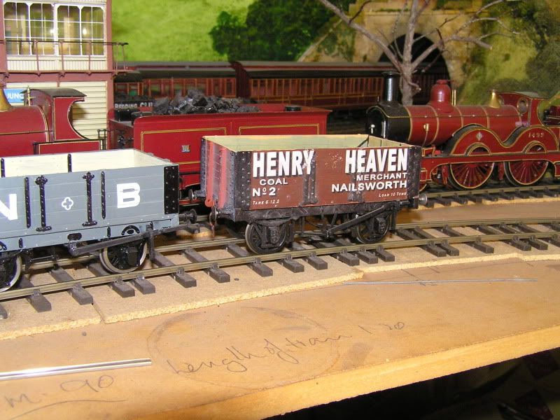  The photos were taken a while back and shows the layout as a work in a very slow state of progress...the dust gives it away I'm afraid.  Jim, Edit: I found and added the photo of the 4-2-2 |
|
jma1009
Elder Statesman
  
Posts: 5,922
|
Post by jma1009 on May 29, 2012 21:18:16 GMT
hi jim, super pics! thanks! what a super layout and superb locos and rolling stock! almost tempted to change from a brighton and GWR fan to being a fan of Johnson and the Midland!  fantastic work and im sure the Brit will be fantastic too! martin evans did a Johnson 'spinner' in 5"g cheers, julian |
|
|
|
Post by Jim on Jun 11, 2012 8:28:24 GMT
Having come to a temporary halt with the boiler, nothing serious just felt like a break,  I decided to bite the bullet and make my own Ross safety valves for Boadicea as I'd had not been able to get any response from a particular supplier. Articles by Doug Hewson (EiM Oct 2006 p119 the BR Class 4) and Gordon Smith (EiM p20 July 2006) sets out all the basic data needed to get started. As always halfway through the job I suddenly remembered there was a detailed scale drawing of a Ross safety valve in Historic Locomotive Drawings by Roche. It turned out to be invaluable in filling in a lot more detail. Our local code requires some way of locking the adjuster so I made the top flange as a separate item so it could become the locking ring for the adjuster. The pictures show turning off one of the top flanges, the components for the second valve and and the one completed valve. I have yet to locate/make the correct springs. 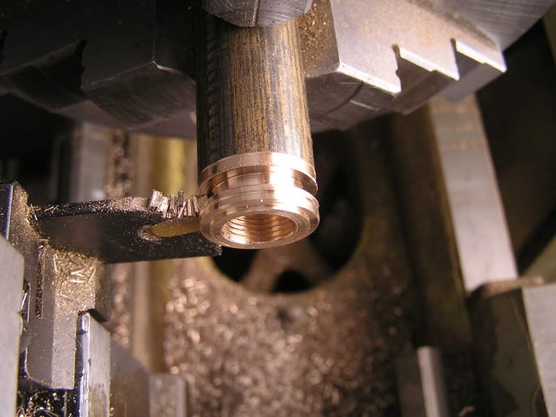 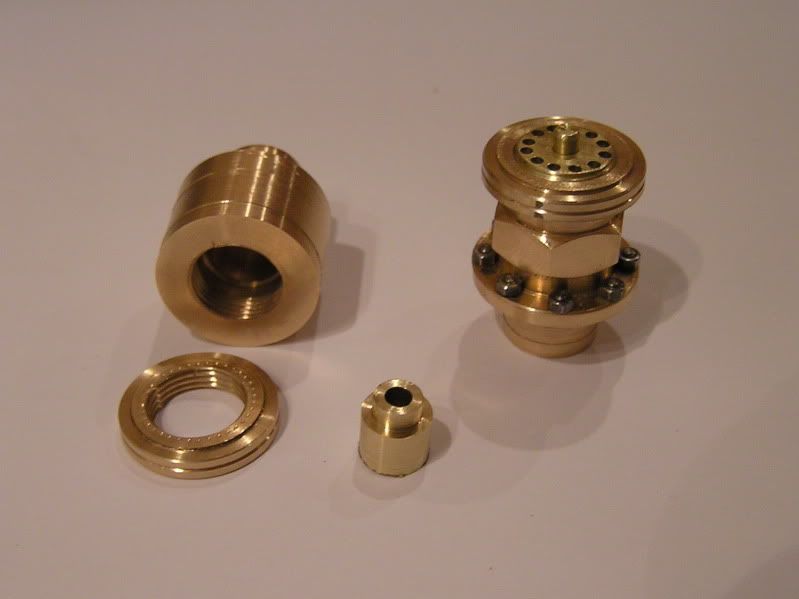 I forgot to mention the other very handy reference for ball valves, clacks etc is the Live Steam Data Sheet, 'Seating Data for Ball Check Valves' by Everett Clem. From memory it was available on the Live Steam website. Now for a soothing ale even if it is freezing outside  Jim. |
|
|
|
Post by Shawki Shlemon on Jun 12, 2012 9:15:39 GMT
Well done Jim , why buy when you can make them ? The satisfaction in making them is the greatest reward . ;D
|
|
|
|
Post by Deleted on Jun 12, 2012 18:37:24 GMT
Very nice Jim
Pete
|
|
|
|
Post by Jim on Jun 12, 2012 22:40:17 GMT
Thanks Pete and Shawki. It's great to see you back on site Pete.  Wise words as always Shawki but at the time I thought I didn't have the materials to make the valves, so buying looked a cheaper option. Then when that fell through a final desperate, 'I must have something somewhere in all this scra...errr... stock' I discovered an off cut of bronze almost made to order. ;D ;D Jim |
|
|
|
Post by Deleted on Jun 16, 2012 22:21:19 GMT
thanks Jim, I do pop in to see what's going on so not really been away, just not posting much. As soon as I get sorted with the house, garden and car I'll be able to get back to Model Engineering which I'm missing greatly, can't wait to get back on FS...  Regards Pete |
|
|
|
Post by Jim on Jun 16, 2012 23:07:36 GMT
Look forward to seeing the upate photos on Flying Scotsman and I'm sure the house, garden and car won't be upset with a change of focus Pete. The domestic authorities may have a different view though.   |
|
|
|
Post by Jim on Jun 22, 2012 23:40:52 GMT
Things have been moving a bit more slowly here as winter tightens it's grip and the ski resorts to the south of us rejoice in the heavy snow falls.  Boadicea's boiler is on hold as I decided a change of activity would be good for the soul. The castings for the Everlasting blow down valve arrived so started machining the parts along the lines described in Doug Hewson's series in EiM. The valve looks very tiny and dainty but I'm assured it will really do the job...when the boiler's completed that is  The photo shows a trial assembly of the valve body. 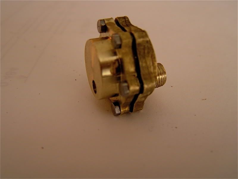 Jim |
|
|
|
Post by Jim on Jun 24, 2012 1:37:08 GMT
Back on safety valves because it's too cold outside for boiler work.  Well that's my excuse and I'm sticking to it.  Now completed both valves but unfortunately I couldn't locate the recommended SS springs locally so decided to wind my own from some SS wire I had. The valves work well when tested on compressed air, releasing at 85 psi. I suspect I will need a stronger spring if required to release at 100psi The photo shows the valve parts. 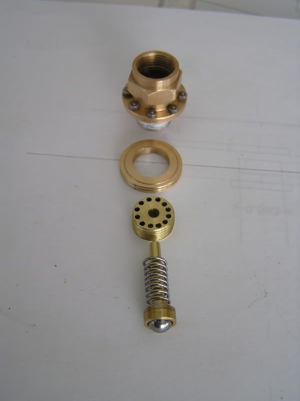 Jim. |
|
|
|
Post by Shawki Shlemon on Jun 24, 2012 9:08:27 GMT
Very nice Jim .
|
|
peteh
Statesman
  Still making mistakes!
Posts: 760
|
Post by peteh on Jun 24, 2012 11:24:11 GMT
Ditto  |
|
|
|
Post by Jim on Jun 24, 2012 12:02:19 GMT
Thanks Shawki & Pete, actually making the springs turned out to be quite interesting once I got the tension right, about middle C when when plucked was what I settled on. I could be tone deaf though ;D ;D All the details can be found at home.earthlink.net/~bazillion/intro.html if anyone is thinking of having a try. Jim |
|
|
|
Post by Jim on Jun 28, 2012 12:00:11 GMT
Been back working on the Everlasting Blowdown valve which has turned out to be an interesting task and rather fiddly. The valve is controlled by a moving arm that contains a very small pressure button to seal the outlet when the arm is in the closed position. The first photo shows the arm mounted on mandrel for ease of holding while shaping with a file. The recessed hole is for the sealing button. 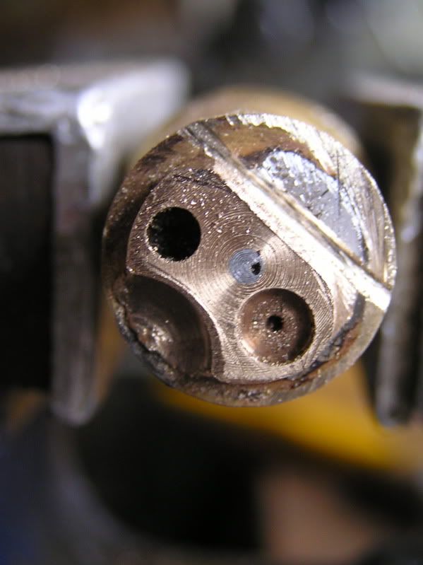 The second pic shows the completed parts with a temporary actuating rod fitted. 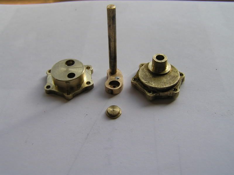 The final pic is of the outer face of the valve with the valve arm in the open position. 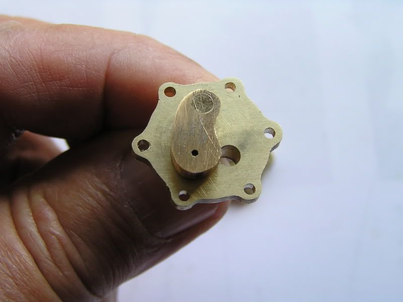 I must hook it up to the water tap and give it a test run before I fit it to the boiler. Aaaah yes the boiler I will get back to it. ;D PS: Due to a lack of drawings/instructions regarding the valve's assembly I'm not confident that the valve, as I have made it is reliable so I have since purchased a ready to run valve from DNC Technologies. |
|
|
|
Post by Jim on Jul 9, 2012 14:37:33 GMT
I realized yesterday that I hadn't completed the lubricator linkages, a job I'd meant to do while I was still working on the valve gear.  A check of the drawings indicated the crank on the outer end of the expansion link trunnion should be 3/4" long, which seemed very big especially when in reality the crank was a very small thing not much longer than the radious of the trunnion's bearing plate. In the end I decided to compromise at 1/2" long cranks. After drilling the holes for the shaft and wrist pins I soft soldered to two small cranks to a brass plate to secure them while milling as seen the first pic. 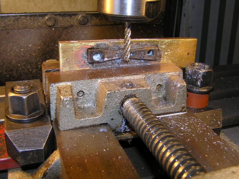 The second pic shows a trial fit of one of the cranks to check the alignment with the lubricator before milling the sides and polishing. 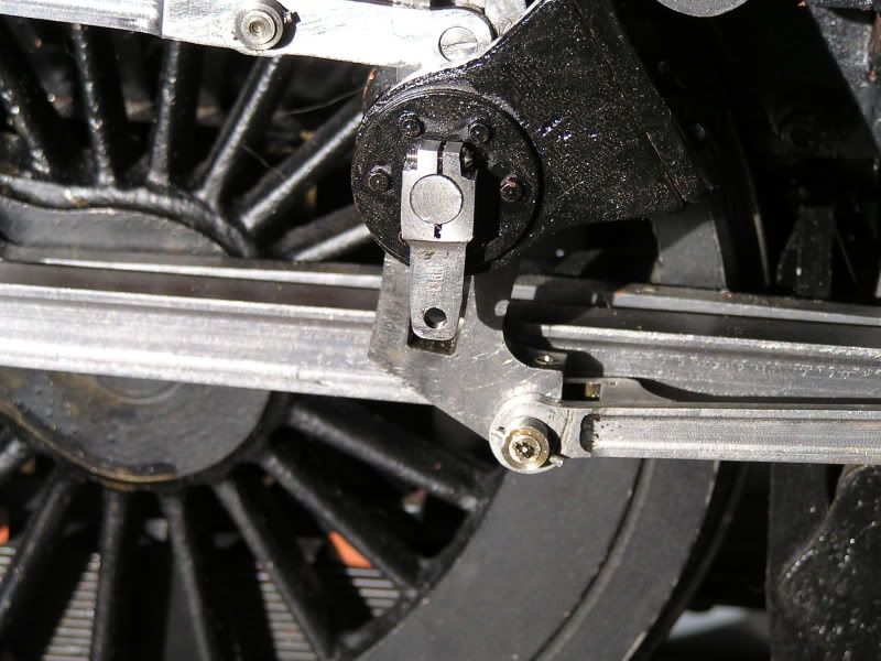 The job for tomorrow will be to make the two drive rods with their forked ends. It's a slow build but fun.  Jim |
|
|
|
Post by Deleted on Jul 9, 2012 18:54:50 GMT
Hi Jim
The cranks look very nice.
Looking at one of your earlier photos, your lubricators look the same as the Steamfittings ones on my Modelworks Britannia, with clutches rather than ratchets. On mine the cranks on the lubricators are 1 3/4" between centres and the cranks on the expansion links are 1 1/8". I made 3 holes for adjustment in the latter cranks, but the middle holes at 1 1/8" seem to work best. There is a tiny bit of backlash on the clutches before they grip, which is exacerbated if any oil gets onto the clutches. Running with the shorter throw caused them sometimes not to get over the maximum pressure point of the pump's revolution.
I don't understand why both cranks are so long - there is no significant strain on the drive rods, particularly if the clutches are arranged so that the rods are pulling rather than pushing on the power stroke, and the shorter cranks do as you say look more realistic. However I think with the shorter drive crank you might also need to shorten the lubricator crank proportionately in order to get sufficient angular movement at the clutches to overcome any backlash.
If the lubricators then deliver too much oil, I believe that it's possible to fit thinner spacers between the 2 O-rings in the pumps, although I haven't tried this myself yet. My lubricators give perhaps slightly more oil than necessary, but better that than too little.
Regards, John
|
|