|
|
Post by yorkshireman on Jan 11, 2019 8:06:04 GMT
On using a Scout whistle on a loco... All such whistles are designed for air. But the sound of such whistle can be greatly inproved, if the whistle is operated indirectly by steam, so that the whistle is operated essentially by air. I made an experiment where a small jet of steam pulled a larger volume of air into the whistle: Very nice sound! This works even better with a "Three-tone Whistle Referee Whistle" or "Taxi Whistle" www.amazon.com/Special-Referee-Whistle-Three-tone/dp/B01EFLTGGSIn this case it is not "seeing is believing" but "hearing is believing" - Try it out Johannes |
|
|
|
Post by Roger on Jan 11, 2019 8:49:33 GMT
On using a Scout whistle on a loco... All such whistles are designed for air. But the sound of such whistle can be greatly inproved, if the whistle is operated indirectly by steam, so that the whistle is operated essentially by air. I made an experiment where a small jet of steam pulled a larger volume of air into the whistle: Very nice sound! This works even better with a "Three-tone Whistle Referee Whistle" or "Taxi Whistle" www.amazon.com/Special-Referee-Whistle-Three-tone/dp/B01EFLTGGSIn this case it is not "seeing is believing" but "hearing is believing" - Try it out Johannes Hi Johannes, That's an interesting idea, do you have any sketches of what you tried? |
|
JonL
Elder Statesman
   WWSME (Wiltshire)
Posts: 2,991
|
Post by JonL on Jan 11, 2019 9:05:39 GMT
Just before reading this most recent post I purchased an old police whistle online for some experimentation! Using a venturi on the inlet (in a similar manner to an injector) would I agree cause an interesting change in tone. For the evenings where I don't feel like working directly on the Brit I plan some experimentation. A similar design to a Steam powered Vacuum generator?
Roger, I've temporarily mislaid the ME magazine with the Chime whistle in but I shall keep looking.
|
|
Lisa
Statesman
 
Posts: 806 
|
Post by Lisa on Jan 11, 2019 9:57:47 GMT
Now after all the wonderful electronics of the Weigh in. The way to a perfect pitch is to borrow the sound card technology from the O Gauge Boys and Girls and do it with a wisp of Steam issued from the right place and a micro switch behind that activates the whistle stored in the little black box! 2 micro speakers on the driving trolley and we are off to a winner? David and Lily. "Nice loco, shame about the sound," is my usual thought on hearing electronic/recorded sounds. Even with properly set up undistorted sounds, they still sound unnatural to my ears. Whether it's the sound not suiting the scale of the model, background noises in the recording (not like they can put a fullsize loco in a sound studio to record it), 'chopped' beginnings and ends to the sounds, the volume not matching the sound effect, obvious repeating of a recording, sounds not synchronised to the actual loco, recorded sounds blocking out real sounds, or a combination of these, it's always so blatantly artificial. Similarly, there was a clock tower on a shopping centre near me a while back, it had full westminster chimes provided electronically from a recording; there were so many complaints that the sounds were removed within a couple of months. |
|
|
|
Post by coniston on Jan 11, 2019 21:19:57 GMT
Pete - Doubletop - provided an excellent spread sheet and much commentary on miniature whistle design last year. Well worth looking at again. Cheers, Julian Hi Julian, I did mention that I'd seen that thread, but there were no accompanying diagrams to show that the dimensions referred to. Maybe that's obvious to some, but not to me. I'm a pictures person, not a numbers one. Hi Roger, if you have downloaded the excel spread sheet 'Whistle Parameters V6' you will see five worksheets, the one titled 'Terminology' has a drawing showing what all the relevant dimension refer to. hope this helps. |
|
|
|
Post by andyhigham on Jan 11, 2019 22:21:32 GMT
A small whistle can never sound the same as a full size one, but if you tune it to the same note a few octaves higher it will have a similar "sound"
|
|
|
|
Post by Roger on Jan 11, 2019 22:45:08 GMT
I wasn't happy with the hex pocket in the bottom of the hand brake column, the corners needed to be a bit sharper to give a longer flat on the hex. This is the setup, holding it in the tapered clam shells I made to hold it when it was first made. The parallel is clamped on the face so I can clock it and tap it round until it's square. 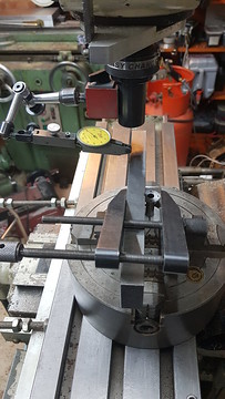 20190108_225303 20190108_225303 by Anne Froud, on Flickr Then I used a 2mm PCB burr to gently ease out the corners... 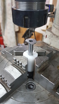 20190109_094952 20190109_094952 by Anne Froud, on Flickr ... before finishing off with a very long 1.5mm PCB 2-flute. 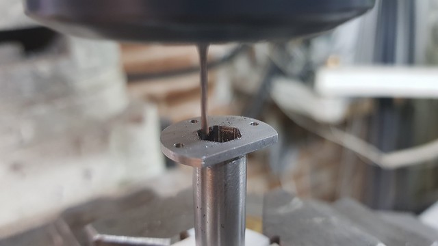 20190109_100438 20190109_100438 by Anne Froud, on Flickr Getting a long hex machined with a parallel end mill is troublesome, it's almost certainly going to end up narrower at the top. To avoid that, I'm using a 16mm 2-flute cutter with inserts that only touch at the tip. 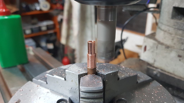 20190109_171616 20190109_171616 by Anne Froud, on Flickr A couple of flats were added and the end rounded off. 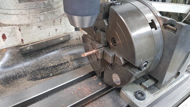 20190110_171004 20190110_171004 by Anne Froud, on Flickr So far so good... 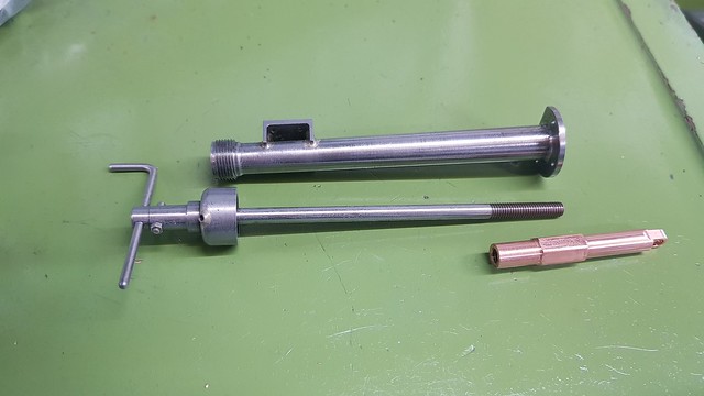 20190110_171824 20190110_171824 by Anne Froud, on Flickr ... or not. Hmmm, I now realise that I'm not going to get 14mm stroke, and that's what it's dawned on me that I'll need. Doh! 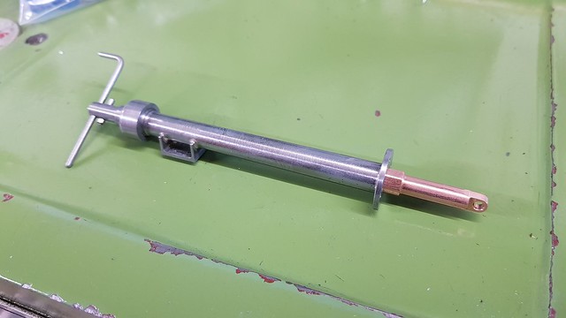 20190110_171949 20190110_171949 by Anne Froud, on Flickr 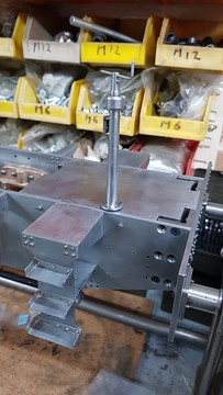 20190110_172039 20190110_172039 by Anne Froud, on Flickr The solution is to add a hex guide to the cab stretcher to guide the hex further down. 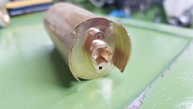 20190111_143439 20190111_143439 by Anne Froud, on Flickr This is what I ought to have done in the first place, making the hole in the brake column circular. 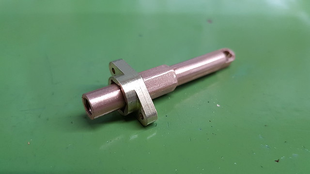 20190111_150353 20190111_150353 by Anne Froud, on Flickr 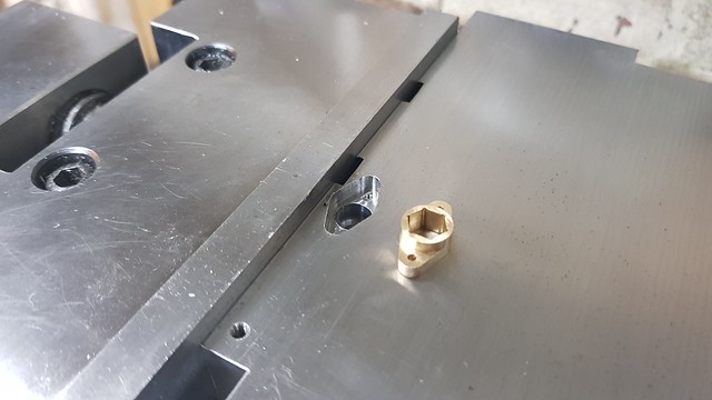 20190111_221640 20190111_221640 by Anne Froud, on Flickr |
|
JonL
Elder Statesman
   WWSME (Wiltshire)
Posts: 2,991
|
Post by JonL on Jan 11, 2019 23:21:31 GMT
Victory snatched from the jaws of defeat. Another elegant solution.
|
|
|
|
Post by Roger on Jan 12, 2019 19:46:13 GMT
This is the brake actuating arrangement which is far from prototypical. 1501 has the steam brake cylinder on the other side of the brake shaft because it pulls up rather than pushes down. Mine is using the LBSC arrangement which was already too far along the design road to change. There were a load of holes in the frames and the various brackets already made, so it seemed crazy to rework it all when it's barely visible. There was no hand brake on LBSCs version so I've added that. I presume he arranged the cylinder that way round to avoid the necessity of a gland seal on the piston shaft. Anyway, it's just a functional item that just needs to not be too offensive to the eye. Today's questions concern the condensation of steam in the brake cylinder and the return spring arrangement. The LBSC design has a drain cock in the top of the steam brake cylinder with the operating lever going up through the floor of the cab. On the club locomotives, there isn't a drain cock. There is a potential problem because I can't pipe away the exhaust from the steam brake, it comes out through a hole in the back of the Combined Steam and Vacuum brake valve. I'd be glad of any thoughts on what's the best thing to do about this. LBSC uses a separate lever and return spring, but I can't see why the steam brake arm can't have a spring attached to it and the other end being attached to the underside of the cab stretcher. I presume some sort of spring is desirable? 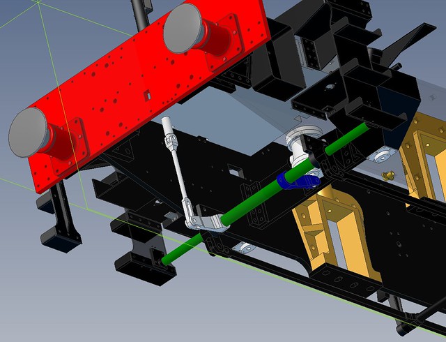 Brake actuating arrangement Brake actuating arrangement by Anne Froud, on Flickr |
|
mbrown
Elder Statesman
  
Posts: 1,795
|
Post by mbrown on Jan 12, 2019 20:27:24 GMT
For a steam brake cylinder where the piston pushes down to apply the brake, you can put a small ball valve inside the piston to act as a drain. It can be held off its seat by a very light spring so that water above the piston drains away through a vent on the under side of the piston, but Don Young suggested that the ball acts rather like the balls in automatic drain cocks and effectively "floats" if there is water above the piston, only seating when the water has gone and steam pressure builds up.
I put this arrangement on the steam brake on my BMR loco, using a nitrile ball in the hope that it would float when clearing the water and wouldn't need a spring. Like your arrangement, it is hidden away between the frames so it isn't easy to see how well it works, but there is no leakage when the steam brake is applied and no apparent problem with condensation despite a lengthy (8") unlagged feed pipe. The steam brake proved good enough to stop the loco rolling back on a steep gradient, although I wouldn't use it to try to stop a train.
Drawings for the drain valve inside the piston are to be found in several of Don Young's designs.
Malcolm
|
|
|
|
Post by Roger on Jan 12, 2019 20:34:42 GMT
For a steam brake cylinder where the piston pushes down to apply the brake, you can put a small ball valve inside the piston to act as a drain. It can be held off its seat by a very light spring so that water above the piston drains away through a vent on the under side of the piston, but Don Young suggested that the ball acts rather like the balls in automatic drain cocks and effectively "floats" if there is water above the piston, only seating when the water has gone and steam pressure builds up. I put this arrangement on the steam brake on my BMR loco, using a nitrile ball in the hope that it would float when clearing the water and wouldn't need a spring. Like your arrangement, it is hidden away between the frames so it isn't easy to see how well it works, but there is no leakage when the steam brake is applied and no apparent problem with condensation despite a lengthy (8") unlagged feed pipe. The steam brake proved good enough to stop the loco rolling back on a steep gradient, although I wouldn't use it to try to stop a train. Drawings for the drain valve inside the piston are to be found in several of Don Young's designs. Malcolm Hi Malcolm, That's brilliant, I'll do that then. A simple but effective solution. I'll see if I can use the same idea I used on the inlet ball valve of the axle driven pump where I hold the ball off the seat with a length of 1mm diameter 'O' ring cord that goes across just below the ball. |
|
mbrown
Elder Statesman
  
Posts: 1,795
|
Post by mbrown on Jan 13, 2019 11:44:46 GMT
I'd forgotten about your cunning ruse to hold balls off their seat! Sounds ideal.
Malcolm
|
|
|
|
Post by Roger on Jan 13, 2019 13:20:15 GMT
I'd forgotten about your cunning ruse to hold balls off their seat! Sounds ideal. Malcolm Hi Malcolm, Here's the detail of that arrangement. The 2mm Silicon Nitride ball is kept in place by an M2.5 Stainless Grub screw. The ball sits on a piece of 1mm section 'O' ring cord. I ought to mention that there's a hole in the grub screw and there's a small clearance past the ball because I'm using 2.1mm as the tapping size for the grub screw. I'll only tap it deep enough for the grub screw to just clear the surface. Simple, but it does have to me made accurately. 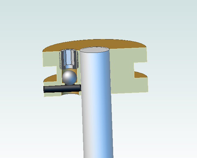 Piston rod assembly Piston rod assembly by Anne Froud, on Flickr |
|
mbrown
Elder Statesman
  
Posts: 1,795
|
Post by mbrown on Jan 13, 2019 14:04:49 GMT
Looks like it just fits.
I think your brake cylinder is mounted on trunnions so a solid piston rod attached to the brake shaft is possible. My cylinder is solidly mounted between the frames so my piston has a trunk beneath the bit that slides in the cylinder with a pivoted link connecting the trunk to the shaft. That means my drain valve can go down the centre of the piston and the condensate exits through a hole in the side of the trunk just above the pivoting link. That gives me a lot more room to play with!
Malcolm
|
|
|
|
Post by Roger on Jan 13, 2019 14:18:05 GMT
Looks like it just fits. I think your brake cylinder is mounted on trunnions so a solid piston rod attached to the brake shaft is possible. My cylinder is solidly mounted between the frames so my piston has a trunk beneath the bit that slides in the cylinder with a pivoted link connecting the trunk to the shaft. That means my drain valve can go down the centre of the piston and the condensate exits through a hole in the side of the trunk just above the pivoting link. That gives me a lot more room to play with! Malcolm It's a bit fiddly, but I think it's ok. Yes, the cylinder is on trunnions, but that doesn't preclude having the valve in the shaft really. Anyway, I'll give it a go and see if it works out ok. |
|
don9f
Statesman
  Les Warnett 9F, Martin Evans “Jinty”, a part built “Austin 7” and now a part built Springbok B1.
Posts: 961 
|
Post by don9f on Jan 13, 2019 17:29:34 GMT
Hi, my 9F brake cylinders have exactly the same drain valve arrangement as described by Malcolm above and always worked well. Real ones are more complicated and use a two part piston head and tapered section rings in a tapered groove that get “squeezed” into contact with the cylinder wall when pressure is applied and relax away from the cylinder wall when released.....condensate then just runs past the piston and down the trunk.
A brake pull-off spring could be advantageous and fitted as you suggested, but with no pressure in the brake cylinder (assuming no tightness), the rigging will just relax and the blocks should move back slightly as the wheel sets move in their suspension. On my loco there are no pull-off springs, but there are on real ones!
Depending on how the brake hangers and brake blocks are made, the blocks may well “hang” such that their top edges run against the wheels even with the brakes off.
Cheers Don
|
|
|
|
Post by Roger on Jan 13, 2019 17:33:57 GMT
Hi, my 9F brake cylinders have exactly the same drain valve arrangement as described by Malcolm above and always worked well. Real ones are more complicated and use a two part piston head and tapered section rings in a tapered groove that get “squeezed” into contact with the cylinder wall when pressure is applied and relax away from the cylinder wall when released.....condensate then just runs past the piston and down the trunk. A brake pull-off spring could be advantageous and fitted as you suggested, but with no pressure in the brake cylinder (assuming no tightness), the rigging will just relax and the blocks should move back slightly as the wheel sets move in their suspension. On my loco there are no pull-off springs, but there are on real ones! Depending on how the brake hangers and brake blocks are made, the blocks may well “hang” such that their top edges run against the wheels even with the brakes off. Cheers Don Hi Don, That certainly does sound complicated in full size, doubtless for a reason though. I think I ought to provide a pull off spring then, I can adjust the strength to get the desired pull back. |
|
don9f
Statesman
  Les Warnett 9F, Martin Evans “Jinty”, a part built “Austin 7” and now a part built Springbok B1.
Posts: 961 
|
Post by don9f on Jan 13, 2019 17:51:14 GMT
Yes and just re-read your post above about “exhausting” the brake cylinder. Is there a way of attaching a pipe somehow to the hole in the rear of the brake valve? Don’t think you’d want it exhausting all over the backhead!
Again harping on about real ones....sometimes the brake exhaust was diffused into the ashpan but then there could be a considerable amount of steam to get rid of....certainly on tender engines with two or more cylinders.
Don
|
|
|
|
Post by Roger on Jan 13, 2019 19:51:10 GMT
This is the steam brake cylinder body which I've chosen to fabricate from three parts, the body and the trunnion pivots. The 3.1mm grooving/parting tool is ideal for machining out the middle part between the flanges. I plunge this repeatedly to within 0.1mm of the final depth to rough out the bulk of the material, then plunge in at the RH flange to the full depth, turn right to left and then pull out to tidy up the LH end. If you have the budget to get one of these, it's something I can highly recommend. The parting/grooving blade has a Vee groove on the top and bottom to stop it from moving sideways, and the clamp is by a Cap Screw holding it down top to bottom.  20190113_115958 20190113_115958 by Anne Froud, on Flickr This is the result. 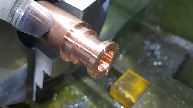 20190113_122547 20190113_122547 by Anne Froud, on Flickr The piece was clocked up true to the axis of rotation of the rotary table and the angle set to zero for this side and 180 to do the other. The pocket is 2mm deep and is to be an interference fit on the pivot stubs so they hold themselves in place for Silver Soldering. 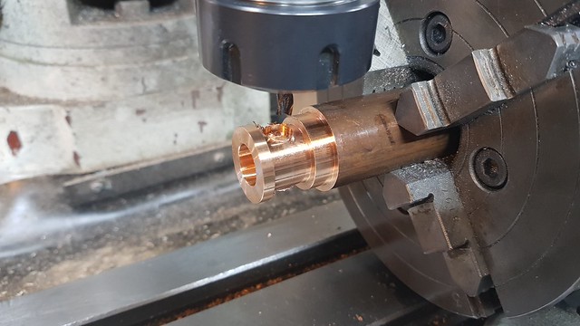 20190113_151052 20190113_151052 by Anne Froud, on Flickr While it's still in the rotary table chuck, It may as well get the tapped holes in one end done. 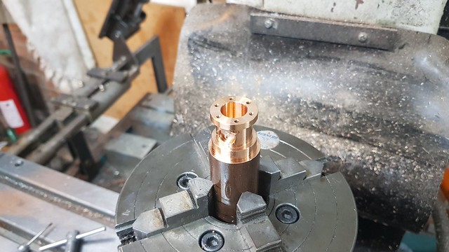 20190113_155020 20190113_155020 by Anne Froud, on Flickr You can't see it in this shot, but I've added notches on the mating faces of the pivot to let the Silver Solder penetrate the joint and stop it being forced out by pressure.  20190113_190009 20190113_190009 by Anne Froud, on Flickr The Silver Solder half round pieces are bent to match the curve of the body as well as round the pivot diameter. Getting it to touch both sides of the joint is essential if it's to bridge them. I've plastered the whole thing in a thin mix of flux... 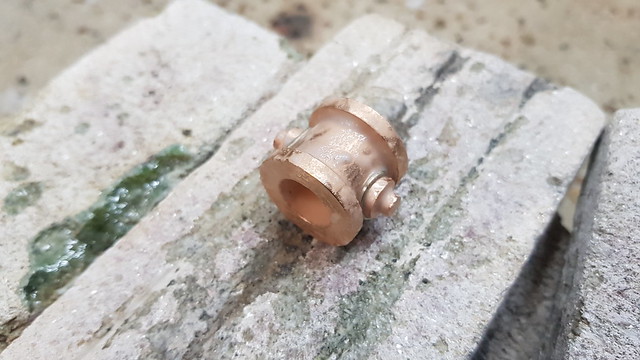 20190113_191311 20190113_191311 by Anne Froud, on Flickr ... then heated it until it melted. 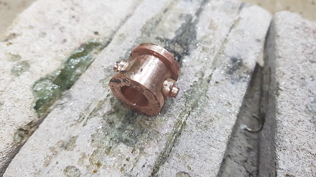 20190113_193416 20190113_193416 by Anne Froud, on Flickr |
|
|
|
Post by Roger on Jan 13, 2019 22:11:32 GMT
Yes and just re-read your post above about “exhausting” the brake cylinder. Is there a way of attaching a pipe somehow to the hole in the rear of the brake valve? Don’t think you’d want it exhausting all over the backhead! Again harping on about real ones....sometimes the brake exhaust was diffused into the ashpan but then there could be a considerable amount of steam to get rid of....certainly on tender engines with two or more cylinders. Don Hi Don, I'm afraid it's not possible to pipe the exhaust, the hole in the back of the brake valve is inaccessible. I'll have to see if it's an issue. If it's really a problem, I suppose I could make a servo kind of arrangement where the volume of steam is much smaller. In reality, it's only about 1-2cc total volume and the pipe can be pretty small, so maybe it won't be a problem. I won't know until I try it. I don't for sure what the full size brake valve does with the exhaust steam, it might get piped into the cavity which is being evacuated by the ejector. There's not much that can be done on mine, but since Julian has used this principle, it makes me think it won't be an issue. Let's hope not. |
|