mbrown
Elder Statesman
  
Posts: 1,795
|
Post by mbrown on Jan 13, 2019 22:23:30 GMT
For what it is worth, on my combined vacuum and steam brake valve I led the steam brake exhaust into the chamber between the cones in the hope that it would be easily exhausted with the air from the vacuum system. When I couldn't get much vacuum on test, I suspected that this arrangement was destroying the vacuum so I re-did it to have a separate exhaust from the valve to below the footplate. However, it made no difference to the vacuum and the problem turned out to lie elsewhere.
That doesn't prove anything (except that one should test everything before modifying anything….) but it suggests that piping the steam brake exhaust into the vacuum exhaust might be OK.
Malcolm
|
|
|
|
Post by Doug on Jan 13, 2019 22:33:09 GMT
Just noticed the last photo, the silver solder fell off to the right so unless you re did it you have a dry joint. looks fab tho.  |
|
jma1009
Elder Statesman
  
Posts: 5,922
|
Post by jma1009 on Jan 13, 2019 22:54:24 GMT
Hi Roger,
I could never get my head round the 'floating ball' type of drain valve/release valve on the Don Young standard steam brake, which is a form of that shown on the Speedy drawings of LBSC.
So I devised a drain/release valve that actually is similar to the Martin Evans standard design. The ball is lightly sprung and with an adjuster set to release at 10 psi. This is a very positive mechanism, and fascinating to watch it take effect. I've made 4 or 5 over the years, and in fact the one I fitted to Stepney's steam brake valve was made some 20 years earlier.
Never had a puff of steam out of the combined vacuum/steam brake valve fitting! But it releases nevertheless in the 'off' position, but the above drain/release valve 'kicks in' very quickly on the outside of the steam brake cylinder.
Brass would have done quite adequately for the steam brake cylinder!
Cheers,
Julian
|
|
|
|
Post by Roger on Jan 13, 2019 23:00:16 GMT
Just noticed the last photo, the silver solder fell off to the right so unless you re did it you have a dry joint. looks fab tho.  Hi Doug, I managed to lose that one when I was setting it up. I only noticed where it had gone after I made a new one! |
|
|
|
Post by Roger on Jan 13, 2019 23:06:37 GMT
Hi Roger, I could never get my head round the 'floating ball' type of drain valve/release valve on the Don Young standard steam brake, which is a form of that shown on the Speedy drawings of LBSC. So I devised a drain/release valve that actually is similar to the Martin Evans standard design. The ball is lightly sprung and with an adjuster set to release at 10 psi. This is a very positive mechanism, and fascinating to watch it take effect. I've made 4 or 5 over the years, and in fact the one I fitted to Stepney's steam brake valve was made some 20 years earlier. Never had a puff of steam out of the combined vacuum/steam brake valve fitting! But it releases nevertheless in the 'off' position, but the above drain/release valve 'kicks in' very quickly on the outside of the steam brake cylinder. Brass would have done quite adequately for the steam brake cylinder! Cheers, Julian Hi Julian, Do you have a sketch of what you're describing? It sounds like it works in the same way, with the exception of having an adjustable setting for the pressure. If that's the case, the question is 'what happens to the steam that's in the cylinder as it drops from say 80psi to 10psi?' Surely that comes out of the Combined vacuum/steam brake exhaust? |
|
jma1009
Elder Statesman
  
Posts: 5,922
|
Post by jma1009 on Jan 13, 2019 23:30:16 GMT
Hi Roger,
Yes, have a few sketches somewhere and can dig them out and send via email.
When you turn the brake valve from 'on' to 'off' the only steam is what is trapped in the pipework and steam brake cylinder, and probably drops in pressure very quickly, and escapes positively as a bit of steam and condensate via the drain/release valve I've mentioned.
Cheers,
Julian
|
|
|
|
Post by Roger on Jan 14, 2019 8:18:19 GMT
Hi Roger, Yes, have a few sketches somewhere and can dig them out and send via email. When you turn the brake valve from 'on' to 'off' the only steam is what is trapped in the pipework and steam brake cylinder, and probably drops in pressure very quickly, and escapes positively as a bit of steam and condensate via the drain/release valve I've mentioned. Cheers, Julian Thanks Julian, I'll be interested to see that. I'm trying to imagine what happens in the design with the ball in the piston. Again, the pressure will drop quickly, and that ought to make any droplets turn into steam. Once the pressure has dropped enough for that ball valve to open, cold air will be drawn in and that will condense any remaining steam to water. |
|
|
|
Post by Roger on Jan 14, 2019 21:53:36 GMT
The Silver Solder made a nice fillet, so I'm pleased with that. 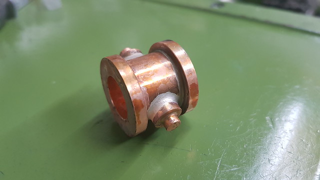 20190114_105756 20190114_105756 by Anne Froud, on Flickr This is using a toolmakers clamp, carefully set so it's sitting square across the face of the pivot pins. The rotary table was adjusted to get this aligned with the Y-axis travel. It's not super accurate, but it's good enough. 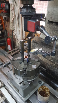 20190114_110849 20190114_110849 by Anne Froud, on Flickr The six M2.5 holes were added to the other end. I didn't mention before that this is made from Phosphor Bronze because there are only a few threads in the flange, and I didn't think Brass would make for very strong threads. 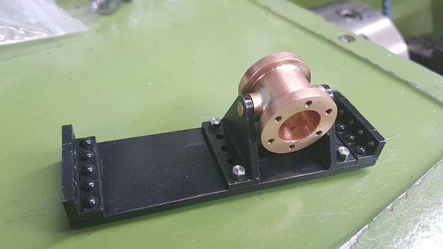 20190114_115347 20190114_115347 by Anne Froud, on Flickr The top is Brass though. You can see the 0.8mm deep pocket for the 1mm section 'O' ring used to seal the top. 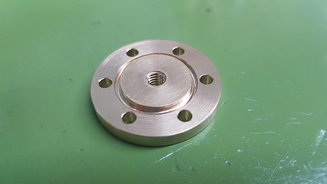 20190114_195406 20190114_195406 by Anne Froud, on Flickr The bottom cylinder cover is also Phosphor Bronze because the piston rod runs through it. This are the soft jaws being clamped down on a piece of Steel so I can turn the location on the back of the cylinder cover... 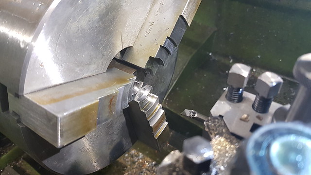 20190114_204910 20190114_204910 by Anne Froud, on Flickr ... using the boring bar and running the lathe in reverse. I touched the back of the body diameter with the tool, then set the DRO to minus that diameter. This gave an initial setting. 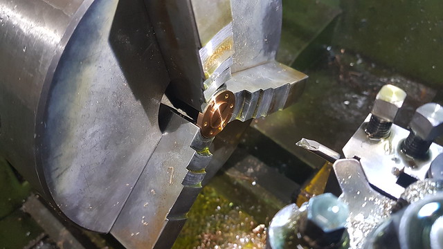 20190114_210847 20190114_210847 by Anne Froud, on Flickr The whole thing goes together like this. 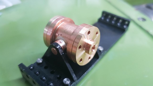 20190114_213413 20190114_213413 by Anne Froud, on Flickr |
|
|
|
Post by David on Jan 14, 2019 22:58:13 GMT
Very nice, as usual. "not super accurate, good enough" - have those words appeared in this thread before?
I was watching Tom Lipton (oxtoolco) video last night where he was joking about how if there is a dial indicator on something a machinist can't stop fiddling until the needle stops moving :)
|
|
|
|
Post by Roger on Jan 15, 2019 8:16:20 GMT
Very nice, as usual. "not super accurate, good enough" - have those words appeared in this thread before? I was watching Tom Lipton (oxtoolco) video last night where he was joking about how if there is a dial indicator on something a machinist can't stop fiddling until the needle stops moving  Guilty as charged! Although, I will tolerate a small movement, say a couple of microns. I suppose it comes from working on super precision high speed spindles, where the smallest of errors in concentricity are enough so seize a spindle at 100,000RPM In my defence, the more you clock things up, the quicker you get at it. I reckon it takes 30-60 seconds to clock something in the Grip-Tru chuck on the lathe. I've created programs to move the mill back and forth to clock things quickly on that too. Personally, I think it's a good habit to get into, I think it saves time in the long run and you have the satisfaction of knowing it's as good as you can make it. |
|
|
|
Post by Cro on Jan 15, 2019 8:29:38 GMT
|
|
|
|
Post by Roger on Jan 15, 2019 9:22:01 GMT
Oh dear, that's not even close. Prototype or not, someone clearly has no idea about accuracy. |
|
|
|
Post by David on Jan 15, 2019 9:47:57 GMT
Even I can do better than that.
I found it interesting that on Keith Applegate's YouTube videos about the little Chinese loco he bought he had to put the disclaimer at the front that it wasn't a Kingscale or whatever else. Yet who would believe there is more than one place in China making the things and that there's any difference in finish or parts between any of the 'brands'.
|
|
|
|
Post by Roger on Jan 15, 2019 10:21:15 GMT
Even I can do better than that. I found it interesting that on Keith Applegate's YouTube videos about the little Chinese loco he bought he had to put the disclaimer at the front that it wasn't a Kingscale or whatever else. Yet who would believe there is more than one place in China making the things and that there's any difference in finish or parts between any of the 'brands'. It's certainly a mistake to assume that everything Chinese is poorly made, just like people used to call Japanese products 'Jap crap'. Who's laughing now, they have the tightest quality control of just about any manufacturers when it comes to car production, and often top the charts in the JD Power consumer satisfaction survey. Whether it's Japan, South Korea, or now China, these are very clever people with a huge drive to better themselves. Much of the precision manufacturing is now done in China, and the quality of many products is improving year on year. I buy my PCB cutters from China, and they're arguably the best in the world at making those. |
|
|
|
Post by delaplume on Jan 15, 2019 10:28:21 GMT
Hi Roger,
Glad to see our good friend "The Micron Kid" is still in town ---LoL !!
Yes, I also suffer from this "Clocker's disease"....Only last night I was setting up another of those Great Bear axles in the 4-jaw with a DTI and had got to within 0.005" concentricity and should have stopped there.........after all a 5 thou run-out on a 3" wheel is neither here nor there...
But could I stop ??........No, of course not and wasted another 10 mins chasing that elusive "Static at zero" needle...
I had to chuckle when you say quote}-- " I will tolerate a small movement, say a couple of microns.".... as I usually say}---" I will tolerate a few thou"....
Horses for courses is what it comes down to I suppose ??
What clearance have you given the cylinder trunnions in the brackets ??..........If you want the piston to fall under light spring or own weight force then I'd be inclined to be generous, say 0.010" - 0.015" ( 1/64" )......this will allow the cylinder to move that very small angular amount needed without getting stuck through expansion or grime etc....
My memory of machining bearings for freight wagon brake linkage at the SVR was that we gave approx 0.030" between a shaft and bush to ensure that the brakes would release no matter how cold or dirty they were.....
The same applied for brake blocks and their locating pins....
I do read your 1501 progress frequently although programming the tool paths etc. is beyond me alas....
Happy days !!
Alan
|
|
|
|
Post by Roger on Jan 15, 2019 10:47:49 GMT
Hi Roger, Glad to see our good friend "The Micron Kid" is still in town ---LoL !! Yes, I also suffer from this "Clocker's disease"....Only last night I was setting up another of those Great Bear axles in the 4-jaw with a DTI and had got to within 0.005" concentricity and should have stopped there.........after all a 5 thou run-out on a 3" wheel is neither here nor there... But could I stop ??........No, of course not and wasted another 10 mins chasing that elusive "Static at zero" needle... I had to chuckle when you say quote}-- " I will tolerate a small movement, say a couple of microns.".... as I usually say}---" I will tolerate a few thou".... Horses for courses is what it comes down to I suppose ?? What clearance have you given the cylinder trunnions in the brackets ??..........If you want the piston to fall under light spring or own weight force then I'd be inclined to be generous, say 0.010" - 0.015" ( 1/64" )......this will allow the cylinder to move that very small angular amount needed without getting stuck through expansion or grime etc.... My memory of machining bearings for freight wagon brake linkage at the SVR was that we gave approx 0.030" between a shaft and bush to ensure that the brakes would release no matter how cold or dirty they were..... The same applied for brake blocks and their locating pins.... I do read your 1501 progress frequently although programming the tool paths etc. is beyond me alas.... Happy days !! Alan Hi Alan, Horses for courses indeed. On the Air Bearing spindles (typically 80,000 - 150,000RPM), the air film was 25microns (1 thou) all round, which you had to maintain within 2microns (a tenth) along the whole 25mm shaft/bearing arrangement. The two bearings were 50mm long spaced by about 50mm so it was a tall order to get those in a housing and maintain the tolerance. Any errors means that those high spots where the air film is thinner breaks down and it touches there when it's loaded. We used to get 10Kg side load if it was done correctly before it touched during a static test. It's a fascinating technology. Everything is a bit tight on the whole locomotive really, I will probably have to ease some of the fits. I'll be fitting a spring to pull the brakes off, simply because the piston seal is going to drag. Hopefully most of the tight bits will free themselves off when it gets a good run... eventually! |
|
|
|
Post by Roger on Jan 15, 2019 13:52:44 GMT
Hi Roger, just managed to get to get a photo of the return spring (one each side) I fitted to my Speedy (Saved having to fit another arm to the shaft). It did surprise me how light the springs needed to be, for a reliable return with soft packing on the piston.  Nick. Thanks for that Nick, I wondered about that because on LBSC's plans it certainly looks light. I don't know why he added a separate lever for that, unless it was added as an afterthought. My spring will need to be a little stronger since I'm using an O-ring and the attachment point is going to be about half way along the arm. I'll aim for a very light compression of the O-ring, maybe 5-10% Thinking aloud about this, I think I can get away with using a Silicone O-ring because this isn't going to get particularly hot. Silicone is a lot softer than Viton. I've chosen quite a chunky 2mm section 'O' ring because I think this will handle the sliding action better than a thin section. |
|
johnthepump
Part of the e-furniture
 Building 7 1/4"G Edward Thomas
Posts: 494 
|
Post by johnthepump on Jan 15, 2019 15:45:35 GMT
Oh dear, that's not even close. Prototype or not, someone clearly has no idea about accuracy. I watched this and the following youtube showed Steamwork Shop making Clupet rings very interesting. John. |
|
Lisa
Statesman
 
Posts: 806 
|
Post by Lisa on Jan 15, 2019 16:03:39 GMT
... just like people used to call Japanese products 'Jap crap'. Who's laughing now, they have the tightest quality control of just about any manufacturers when it comes to car production, and often top the charts in the JD Power consumer satisfaction survey. I vaguely recall reading about some business guru who tried to sell the concept that 'high quality costs no more to manufacture than poor quality' to the US car industry; they essentially just laughed at him, so he took the idea to Japan. The result of that is rather obvious. Horses for courses is what it comes down to I suppose ?? It often amuses me when Roger mentions taking fine finishing cuts that are the same or larger than my usual cuts on the mill; all down to the variances of machine sizes and capability no doubt. Horse for courses indeed. |
|
|
|
Post by Deleted on Jan 15, 2019 16:04:03 GMT
Oh dear, that's not even close. Prototype or not, someone clearly has no idea about accuracy. I watched this and the following youtube showed Steamwork Shop making Clupet rings very interesting. John. I watched that too John, I also found it interesting, I met Simon at the Pacific rally in 2016 (Adam introduced me), a very nice guy and dare I say a rare thing in dealer circles...I met Paul Tompkins at the same event, another great trustworthy chap. Pete |
|