|
|
Post by Roger on Oct 25, 2020 11:20:59 GMT
If you mean on the bottom of the gauge, then you will need a blow down to demonstrate that you can clear the glass during the Steam Test. I cannot state whether this is a written test requirement but more than one inspector has asked me to do this. It is also a definite safety aid in checking the water level. Norm Hi Norm, This is purely for my home test boiler, it won't be used elsewhere. I can tip the boiler up if necessary to see what's going on. This is a very crude electric boiler. The worst that can happen if it runs out of water is it will destroy the element. |
|
oldnorton
Statesman
 5" gauge LMS enthusiast
Posts: 694
|
Post by oldnorton on Oct 25, 2020 12:08:46 GMT
Sorry!! complete misreading by me - must pay better attention !!
|
|
|
|
Post by Roger on Oct 25, 2020 18:30:00 GMT
Ok, I've stripped this back to bare metal again. I tried removing the Enamel with Enamel thinners, but now it's dry, there's no way that's coming off. So I used the Universal thinners which dissolves the primer and takes the whole lot off with ease. So on closer examination, I think Chris Vine has put his finger on the issue, which is basically that there's a tiny gap under the rivets because they're cosmetic and just bonded in with Loctite. It's barely noticeable, but it's enough to wick the paint into the joint and then leave a gap where it doesn't bridge across. I think it was Norm who suggested painting around each rivet with primer, apologies if I haven't credited the appropriate contributor! Anyway, that's what I've done with a tiny brush with the primer, and it's taken six applications in succession to finally get to the situation where I can definitely see that the gap has been bridged everywhere. The primer is like water, so it's hardly surprising. I'm not bothered about it building up around the rivet, that can easily be sanded down since it's bare metal as a base. I've also added a bit of primer in a few other places where there were marks that could use filling. Hopefully when I spray the primer this time, it will look better around the rivets.  20201025_162043 20201025_162043 by Roger Froud, on Flickr |
|
|
|
Post by Roger on Oct 25, 2020 21:31:17 GMT
Here's the test boiler blowdown valve which is sealed so that I can pipe the outlet under the door and outside without getting water all over the bench. The yellow washer is captive against the shoulder by the gland nut with a small clearance. Its purpose it just to stop the 'O' ring on the shaft from popping out when the valve is closed.  Blowdown valve Blowdown valve by Roger Froud, on Flickr |
|
|
|
Post by Roger on Oct 26, 2020 16:35:18 GMT
Ok, this is a bit more promising. Here I've sanded around all of the rivets and prepared it for painting.  20201026_105744 20201026_105744 by Roger Froud, on Flickr One the surface it looks ok...  20201026_155146 20201026_155146 by Roger Froud, on Flickr ... but there are a few rivets like the one at the front where I've not cleaned it up enough. I'll let this go off and see if I can carefully correct that. 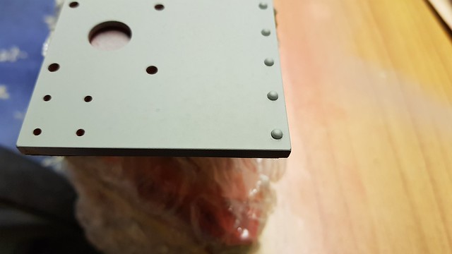 20201026_155139 20201026_155139 by Roger Froud, on Flickr |
|
|
|
Post by Roger on Oct 26, 2020 16:54:42 GMT
This is the test boiler barrel getting the end squared off...  20201026_115628 20201026_115628 by Roger Froud, on Flickr ... before adding a huge weld prep that's 8.5mm deep The barrel and end plates are both 10mm thick, and the intention is to fuse the bottom 1.5mm too. The fit isn't going to be great because it's clearly not round. I'll use the TIG welder to get a lot of heat into the root and then fill the rest.  20201026_164755 20201026_164755 by Roger Froud, on Flickr |
|
|
|
Post by Roger on Oct 27, 2020 11:22:32 GMT
More progress on the test boiler today. This is a redesigned Blowdown valve with a Banjo style attachment so I can get this right at the bottom of the boiler...  Banjo style blowdown valve Banjo style blowdown valve by Roger Froud, on Flickr ... and a modified Clack using the information Chris sent me. I'll have to look at the valve in the Injector if that isn't satisfactory. There's very little room in that one, but I'm sure something could be done to stop the ball blocking the outlet, even if it's just a thin wire across the diameter.  Clack assembly Clack assembly by Roger Froud, on Flickr So this is as far as I've got. The single large outlet on the top can be for a turret or a single valve. It's big enough to attach a connection that could potentially drive the chassis on Steam, albeit saturated steam. So I need to sort out a valve design for the outlet and an attachment point for a pressure guage. Then it's pretty much done.  Test boiler section Test boiler section by Roger Froud, on Flickr I've found a Phase Angle Control board that we used to use on a chiller we used to make, and I'll upgrade that to a 16Amp Triac so it's man enough for the 1.8Kw heating element. I also need to source a PTC that will fit in the thermostat hole so I can get the necessary temperature feedback to that. The plan is to be able to dial in a temperature, and that ought to approximately set the pressure automatically. That would be handy and one less thing to think about while experimenting. |
|
|
|
Post by ettingtonliam on Oct 27, 2020 12:12:01 GMT
This is the test boiler barrel getting the end squared off... 20201026_115628 by Roger Froud, on Flickr ... before adding a huge weld prep that's 8.5mm deep The barrel and end plates are both 10mm thick, and the intention is to fuse the bottom 1.5mm too. The fit isn't going to be great because it's clearly not round. I'll use the TIG welder to get a lot of heat into the root and then fill the rest. 20201026_164755 by Roger Froud, on Flickr Wow! That overhang is a bit scary! Anyway, it worked which is the main thing. |
|
|
|
Post by Roger on Oct 27, 2020 18:05:26 GMT
This is the test boiler barrel getting the end squared off... 20201026_115628 by Roger Froud, on Flickr ... before adding a huge weld prep that's 8.5mm deep The barrel and end plates are both 10mm thick, and the intention is to fuse the bottom 1.5mm too. The fit isn't going to be great because it's clearly not round. I'll use the TIG welder to get a lot of heat into the root and then fill the rest. 20201026_164755 by Roger Froud, on Flickr Wow! That overhang is a bit scary! Anyway, it worked which is the main thing. Fortunately the 4-jaw is a big beast and it's really got hold of the inside. I managed to take a 0.5mm cut off the end without any drama. It also helps knowing that it will stop if it all goes pear shaped. I wouldn't be so confident with a geared lathe. |
|
|
|
Post by Roger on Oct 27, 2020 22:45:01 GMT
More progress on the Test Boiler design. I've moved the water gauge away from the centre line so that I can get the pressure gauge connection higher up. I've also added a large Steam Valve that's not quite finished yet, but that will have a 5mm through hole for a 6mm pipe. I'll step that down to 4mm pipe for the injector testing. I've also added some feet which lifts it enough to give the Blowdown Valve clearance. I've moved the front foot back so I can reach the Blowdown Valve outlet so it can be machined even with the foot in place. I may add that hole first though, we'll see. 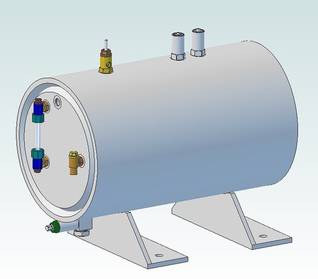 Boiler assembly Boiler assembly by Roger Froud, on Flickr Anyway, here are the two angles being machined for the feet...  20201027_160454 20201027_160454 by Roger Froud, on Flickr ... I'll just weld them on.  20201027_191814 20201027_191814 by Roger Froud, on Flickr I don't intend bolting this to the bench, the holes are at the same spacing as the 'T' slots on the mill so I can easily hold it down while I machine the holes and 'O' ring details on the top. It's a tricky thing to hold otherwise, so this seemed an easy option.  20201027_223229 20201027_223229 by Roger Froud, on Flickr |
|
|
|
Post by rogsteam1959 on Oct 27, 2020 23:09:15 GMT
Hi Roger
Why not putting the pressure gauge connectors on top like the safety valves?
|
|
|
|
Post by Roger on Oct 27, 2020 23:35:15 GMT
Hi Roger Why not putting the pressure gauge connectors on top like the safety valves? I did consider doing that, but it will need a syphon so I thought it might be easier if it came out horizontally. |
|
|
|
Post by steamer5 on Oct 28, 2020 3:23:07 GMT
Hi Roger,
As a suggestion, put a second valve on top that’s big enough to take fittings that you can put safety valves on for testing / setting.... a friend had that on his test boiler & it was most uesful!
Cheers Kerrin
|
|
|
|
Post by Cro on Oct 28, 2020 6:47:37 GMT
Looks great Roger, I’d suggest a second feed clack through for a hand pump so that when testing you have a way of filling the boiler.
I’d highly recommend making the injector test device which I think is in DAG Browns book and having this connected to a second valve off the boiler. This allows you to test against boiler pressure without filling the boiler all the time but having it valved off means you have control of it. You can also measure delivery rate with the outlet of the device.
Adam
|
|
uuu
Elder Statesman
 your message here...
Posts: 2,812
|
Post by uuu on Oct 28, 2020 7:28:20 GMT
Yes, the DAG brown tester is excellent. Seeing the delivered water running out (or dribbling out, if you're less lucky) is a perfect confirmation that things are working.
With a vertical plate at one side of the boiler, you could simulate the frame of the loco, and have pipework etc in all the expected places.
Wilf
|
|
|
|
Post by Roger on Oct 28, 2020 8:50:44 GMT
Thanks to all for the suggestions, I'll be doing some of those. The handy thing about this design is that I can add other connections even when it's finished because the wall thickness is so great. I can put it back on the mill at any time.
|
|
jma1009
Elder Statesman
Posts: 5,901
|
Post by jma1009 on Oct 28, 2020 10:15:22 GMT
A bit off topic, but a proper boiler test rig for miniature injectors for those who - I guess like Roger - will want to know exactly what is happening or not happening as the case may be using a theoretical approach of analysis can include lots of stuff to assist:-
1. Measuring the lift
2. Measuring the temperature of the delivered water, and that which emerges from the overflow
3. Temperature of the water going into the injector
4. Independent measurement of the injector feed pressure range
5. Measuring the capacity of the injector ie feed rate, and also at different steam pressures
|
|
|
|
Post by Roger on Oct 28, 2020 11:31:58 GMT
A bit off topic, but a proper boiler test rig for miniature injectors for those who - I guess like Roger - will want to know exactly what is happening or not happening as the case may be using a theoretical approach of analysis can include lots of stuff to assist:- 1. Measuring the lift 2. Measuring the temperature of the delivered water, and that which emerges from the overflow 3. Temperature of the water going into the injector 4. Independent measurement of the injector feed pressure range 5. Measuring the capacity of the injector ie feed rate, and also at different steam pressures Hi Julian, Thanks for that, I hadn't really got as far as thinking about all of those things, but yes, it would be ideal to be able to do all of that. I'll have to get a thermometer to measure the temperatures. I've got a graduated glass container that will be good for measuring the delivery over time. I can also measure the amount of water drawn from a reservoir. Lots to think about, I'm looking forward to experimenting! |
|
|
|
Post by delaplume on Oct 28, 2020 20:27:36 GMT
Hi Roger,
Glad to see you living up to our original title ie}----- Society of Model and Experimental Engineers !!
PS}-- I would suggest keeping the number of entries into the boiler shell down to a minimum........hence the use of a single manifold with various outlets for the suggestions above.........Also, why have you stipulated 2 safety valves ??....as a test boiler I can't see the need.....
Keep at it....you'll soon be up to 13,000 posts which---if you calculate pro-rata--- means you'll have beaten Lewis Hamilton = Result !!
Best wishes..
Alan
|
|
JonL
Elder Statesman
WWSME (Wiltshire)
Posts: 2,909
|
Post by JonL on Oct 28, 2020 21:27:32 GMT
Redundancy on safety valves surely can't hurt. Better safe than sorry.
|
|


