|
|
Post by steamer5 on Sept 13, 2021 21:28:43 GMT
Hi Rodger,
Nice to hear that the oil got thru! Back in the day when I did viscosity testing the tubes we used had different size bores dependant on the oil being tested. Transformer oil or diesel the bore was very small, fuel oil pretty large, the test temps were always the same no matter what. Looks like surface tension on the left hand box, like you suggest, with the tapered tube fitting is great enough to stop flow given the other flows with the tube that one should be good. When you are running maybe the reciprocating rods will assist in dragging the oil thru as well.
Cheers Kerrin
|
|
|
|
Post by Roger on Sept 13, 2021 22:52:36 GMT
Hi Rodger, Nice to hear that the oil got thru! Back in the day when I did viscosity testing the tubes we used had different size bores dependant on the oil being tested. Transformer oil or diesel the bore was very small, fuel oil pretty large, the test temps were always the same no matter what. Looks like surface tension on the left hand box, like you suggest, with the tapered tube fitting is great enough to stop flow given the other flows with the tube that one should be good. When you are running maybe the reciprocating rods will assist in dragging the oil thru as well. Cheers Kerrin Hi Kerrin, That's interesting, and it certainly makes logical sense. I did wonder about that last point myself. It might be an issue with the main axle boxes, which have a large reservoir and two 1mm holes feeding front and back of the centre line. I guess I could always insert a wire into the hole to reduce the cross section of the hole if that happens. We'll see. Too much is preferable to too little. I'm amazed that some locomotives have just a drilled hole and a chamfer to hold a drop of oil, I don't imagine that will last long. |
|
|
|
Post by terrier060 on Sept 13, 2021 23:31:05 GMT
Hi Roger
I may not have read all the thread properly so apologise if I am talking crap, but I think you answered your own question above. A wick in the top of the pipe going down into the tank breaks any surface tension and the thicker oil should then flow. The constant wick feed keeps the oil moving downwards through the pipe.
|
|
|
|
Post by Roger on Sept 14, 2021 7:01:23 GMT
Hi Roger I may not have read all the thread properly so apologise if I am talking crap, but I think you answered your own question above. A wick in the top of the pipe going down into the tank breaks any surface tension and the thicker oil should then flow. The constant wick feed keeps the oil moving downwards through the pipe. Hi Ed, The pipes inside the tank are almost level with the bottom so there's no need for a wick to carry the oil up and into the pipe as it stands. The one that didn't flow appears to have stopped where the oil drop formed on the outlet of the conical fitting. There's enough surface tension to stop that drop from growing to the point where it drops off. This doesn't happen on the one with the pipes, presumably because there is a surface to carry away the oil drop as it forms. It spreads along the surface and the oil keeps flowing, albeit slowly. |
|
|
|
Post by chris vine on Sept 14, 2021 7:16:51 GMT
two things:
Is there surface tension in oil? Probably yes, but is it in a way that prevents it flowing across metal, or along a pipe. I think that oil just creeps along the surface...
If you want to try drawing down some tube, then I have (somewhere) a draw plate. My late mother was an amateur silversmith, so I have all her tools. It would be interesting to give it a go!!
Chris.
|
|
|
|
Post by 92220 on Sept 14, 2021 8:18:19 GMT
Thanks Bob, It doesn't look like there's anything to the left of the valve gland, so I presume there's just a hole in the top of the gland for the pipe to go into. <Edit> That's what I've done tonight. I've drilled a 1.6mm hole 1.8mm deep to take the pipe, and a 1mm through hole to let the oil out. Looking at where the rear pipe is, I think it must immediately go over the back side of the crosshead casting rather than down where the other one goes. I don't know if there's room for a special box in front of the the main piston gland, it's all pretty tight there. I'll probably just drill a hole in the gland, like the piston valve gland, if there's no room. Hi Roger. If you go back quite a few pages, there is a photo of the loco cylinder from the rear. It shows that pipe I identified as going down the back and into a fitting on the back of the top face of the slide bar where it bolts to the rear of the cylinder, just above the piston rod gland. This seems to indicate that the oil-way goes through the slidebar and then into the gland. 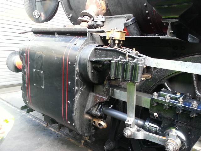 20140204_112524 20140204_112524 by Georgia Montgomery, on Flickr Bob |
|
|
|
Post by 92220 on Sept 14, 2021 8:25:21 GMT
|
|
|
|
Post by Roger on Sept 14, 2021 12:02:52 GMT
two things: Is there surface tension in oil? Probably yes, but is it in a way that prevents it flowing across metal, or along a pipe. I think that oil just creeps along the surface... If you want to try drawing down some tube, then I have (somewhere) a draw plate. My late mother was an amateur silversmith, so I have all her tools. It would be interesting to give it a go!! Chris. Hi Chris, I think the pointed end of the outlet fitting is what stopped the flow. If you imagine a tube where there's a 45 degree chamfer on the end, to the point where there's a sharp edge around the inner hole, that's the situation I've got. It would appear that the oil won't flow back around that sharp edge and it doesn't form a large enough drop to fall away. Maybe I'll have a go at drawing some pipe, thanks for the offer, but for the moment it's going to be good enough. It's certainly an interesting thing to try. |
|
|
|
Post by Roger on Sept 14, 2021 12:08:06 GMT
Hi Bob, It certainly looks like that, doesn't it. I guess it's the only way to feed a pipe into the top of the Oiling box that's bolted in front of the gland. I'll have to take a look and see how that looks on the model. |
|
|
|
Post by Roger on Sept 14, 2021 20:47:33 GMT
This is the last of the front four feed pipes. I managed to drop the hex bolt on the floor, never to be seen again, so this is a new one!  20210914_142329 20210914_142329 by Georgia Montgomery, on Flickr The read ones that feed the Piston Valve Gland have a second bend that is tricky to do because it's hard to hold the first bend. a pair of 3D printed clam shells took 8 minutes to print. They're scurffy, but good enough.  20210914_210643 20210914_210643 by Georgia Montgomery, on Flickr 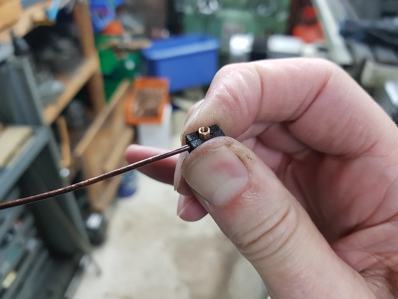 20210914_210724 20210914_210724 by Georgia Montgomery, on Flickr  20210914_211610 20210914_211610 by Georgia Montgomery, on Flickr The bend acutally needed to be slightly tighter than this. I annealed it and adjusted it to suit.  20210914_211717 20210914_211717 by Georgia Montgomery, on Flickr The end was then filed to length so that the pipe can't escape from the gland when the bolts are through the Oil Boxes. Originally I thought that I might have to shorten the threads on the Oil Box on the right because the bolts on the foot base were so close. however, as you can see, there's actually plenty of clearance. 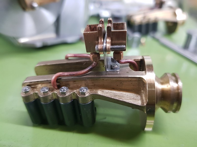 20210914_213636 20210914_213636 by Georgia Montgomery, on Flickr You can just see the pipe going into the gland.  20210914_213717 20210914_213717 by Georgia Montgomery, on Flickr |
|
|
|
Post by Roger on Sept 14, 2021 21:33:06 GMT
This is how the Slide Bar looks on 1501, you can see that the oil pipe goes to a fitting between the bolt and the cylinder. You can also see the huge departure I've made from the original valve gear by adopting Don Ashton's geometry. On my valve gear, the union link is much lower down. You can also see why there's that curve on the underside of the casting to miss the end of the link.  20140204_1125310 20140204_1125310 by Georgia Montgomery, on Flickr The oiling gland looks like this, and it looks like the copper pipe goes into the top. 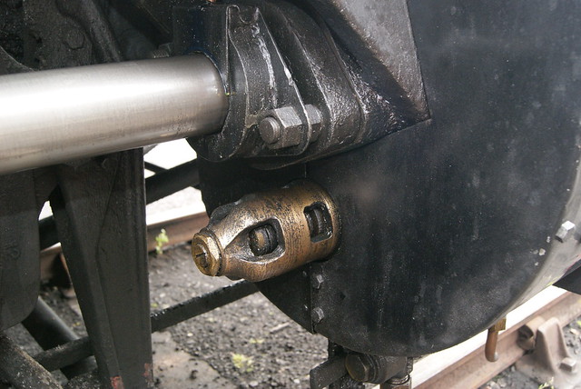 VhwelgE VhwelgE by Georgia Montgomery, on Flickr  20140204_112524 20140204_112524 by Georgia Montgomery, on Flickr If you look at my arrangement, you can see that the piston gland is further away from the Cylinder cover, so I don't think a copper pipe would look right going through the slide bar. I'm inclined to either leave this detail out altogether and just feed the oil pipe into an angled hole in the gland at the back, or alternatively fit an oiling box and do something similar with the pipe entry. Another idea would be to do the first and second options, but make the oil box a dummy, taking the feed to the main gland. I'm not sure what I'll do yet.  Piston gland arrangement Piston gland arrangement by Georgia Montgomery, on Flickr |
|
|
|
Post by Roger on Sept 15, 2021 13:13:28 GMT
Ok, this is one way I could do the piston rod oiler. On 1501, the pipe goes through much closer to the cylinder cover, in fact it's on the other side of the big nut. Actually, on 1501 there are two smaller bolts holding the Slide Bar in place, but it's too late to change that now. In this arrangement, the Slide Bar has an M2.5 thread through it and the fitting screwed into it is just a dummy. It might just be possible to withdraw the joggled copper pipe if that was removed and if I softened the joggle slightly. If not, that would have to stay with the Slide Bar once it's bent. This is the rear view of course, you won't really see the pipe going down.  Piston rod oil piping Piston rod oil piping by Georgia Montgomery, on Flickr This is the side you'll actually see. Although there's a fair bit of artistic license involved in this, it does retain the flavour of how it ought to be done. I think it's better to have that detail on the Piston Rod rather than to leave it off altogether, even thought it's wrong. I presume there's a bronze pipe fitting on the top of the Oiling Gland too, but there isn't really room for one there because the pipe is over scale. The Oiling Gland is probably best made from Phosphor Bronze so that it's rust proof and the thin flange with be strong. I don't think Brass would be strong enough. To disassemble this, the Oil Boxes would have to be unbolted, the dummy gland unscrewed and the pipe slid up out of the Oiling Gland. That's not so bad. I don't want to make something that's a Chinese Puzzle.  Piston rod oil piping with cladding Piston rod oil piping with cladding by Georgia Montgomery, on Flickr |
|
baldric
E-xcellent poster

Posts: 208
|
Post by baldric on Sept 15, 2021 18:35:37 GMT
The piston rod oil pipe just drips oil on to the wiper round the rod, there is no fitting on that end of the pipe, assuming it is a standard GWR fitting, which it looks like. The top cover the pipe goes in through just clips on to the main casting. Here is a picture of one on a King didcotrailwaycentre.org.uk/shopimages/6023%20oil%20pot%20for%20piston%20rod%20small.jpgThis is the same as one on 2 cylinder engines except for the size, and they are handed but I assume as you started with inaccurate drawings yours gland bolts are either side of the rod rather than at 45 degrees, thus yours are not handed. Baldric. |
|
|
|
Post by Roger on Sept 15, 2021 18:50:22 GMT
The piston rod oil pipe just drips oil on to the wiper round the rod, there is no fitting on that end of the pipe, assuming it is a standard GWR fitting, which it looks like. The top cover the pipe goes in through just clips on to the main casting. Here is a picture of one on a King didcotrailwaycentre.org.uk/shopimages/6023%20oil%20pot%20for%20piston%20rod%20small.jpgThis is the same as one on 2 cylinder engines except for the size, and they are handed but I assume as you started with inaccurate drawings yours gland bolts are either side of the rod rather than at 45 degrees, thus yours are not handed. Baldric. Thanks Baldric, that looks exactly like it, albeit with the flange at an angle as you point out. The one on 1501 definitely has that front plate and a clip which you can see on the photo. Unfortunately the photo doesn't quite reveal what's at the top. I've got a hole in the top of mine, so I can hang a little plate like that over the front, held on by the Copper pipe. You're quite right about the glands, they are parallel. However, they aren't at 45 degrees either, they are somewhat less on 1501. |
|
|
|
Post by Roger on Sept 15, 2021 20:52:14 GMT
This is the thin flanged plate on the back of the Oiling Box. It's only 0.5mm thick, which is actually over scale, so it's not going to be very strong. This is a piece of PB102 bar for that. 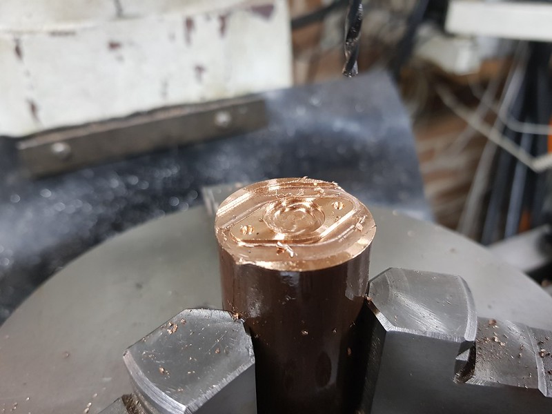 20210915_163041 20210915_163041 by Georgia Montgomery, on Flickr Parting this off to thickness in one cut would end up with it dished, so I'm partially parting it off leaving 1.5mm of thickness to start with. Then I took half a dozen fine cuts on the back with the parting tool to get it to the right thickness.  20210915_181506 20210915_181506 by Georgia Montgomery, on Flickr The register is 0.3mm deep to help centre it for Silver Soldering.  20210915_192416 20210915_192416 by Georgia Montgomery, on Flickr I didn't want to cut the bar down for the body, so it's standing out quite a way more than I'd like. It's still rigid enough to machine this easily.  20210915_192429 20210915_192429 by Georgia Montgomery, on Flickr  20210915_195824 20210915_195824 by Georgia Montgomery, on Flickr The tilting 4th axis was turned horizontally and rotated through 270 degrees so the pipe hole could be drilled. The copper pipe goes in a 1.6mm hole that's 1.8mm deep, and this 1mm hole lets the oil through.  20210915_200938 20210915_200938 by Georgia Montgomery, on Flickr I really like this tool, it's brilliant for creating sharp features like this register. It just needs a little tidying up to make it fit the attachment plate.  20210915_202023 20210915_202023 by Georgia Montgomery, on Flickr The idea is to wedge a scrap of felt in the groove which should distribute the oil. I'm going to use the tried and trusted method of a formed Silver Solder piece to rest in the joint.  20210915_213746 20210915_213746 by Georgia Montgomery, on Flickr |
|
|
|
Post by Roger on Sept 16, 2021 11:43:28 GMT
This is the setup for Silver Soldering, with a weight to make sure it doesn't jump out of the shallow register.  20210916_111100 20210916_111100 by Georgia Montgomery, on Flickr 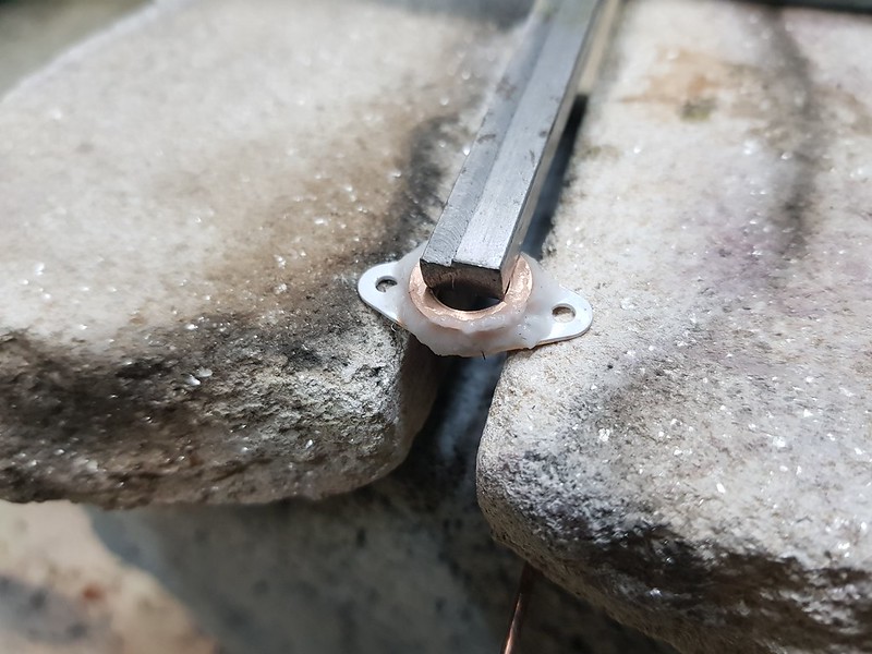 20210916_111106 20210916_111106 by Georgia Montgomery, on Flickr  20210916_111306 20210916_111306 by Georgia Montgomery, on Flickr Now I'm looking at this, I can see that I ought to have realised that this didn't bridge the gap...  20210916_111808 20210916_111808 by Georgia Montgomery, on Flickr ... unlike the first one.  20210916_112622 20210916_112622 by Georgia Montgomery, on Flickr There's plenty of Silver Solder that will pull down into the joint, but I need to make sure the gap does bridge. I've snipped a couple of pieces of Silver Solder from the oversized rods I was sent in error to help with that.  20210916_113349 20210916_113349 by Georgia Montgomery, on Flickr  20210916_113828 20210916_113828 by Georgia Montgomery, on Flickr That looks better this time.  20210916_114120 20210916_114120 by Georgia Montgomery, on Flickr Ok, there's more on one than the other, but I can live with that.  20210916_114447 20210916_114447 by Georgia Montgomery, on Flickr I hadn't noticed that the back turning of the flange hadn't left it completely flat, you can see the interesting pattern that's left. With the benefit of hindsight, I'd have done better to make the flange thicker, Silver Solder it on and than turn it down to thickness. That's what I'll do if I have something similar to make.  20210916_115055 20210916_115055 by Georgia Montgomery, on Flickr Anyway, a rub on some Wet & Dry soon sorted that out.  20210916_115816 20210916_115816 by Georgia Montgomery, on Flickr |
|
|
|
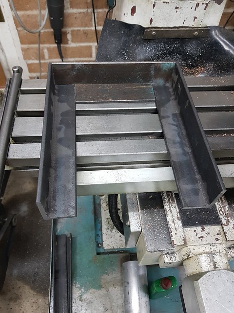
Post by Roger on Sept 17, 2021 20:25:41 GMT
|
|
|
|
Post by springcrocus on Sept 17, 2021 21:13:09 GMT
Based on that amount of overhang, I think you will need a double fixing at the upper part of your bracket. I've seen overloaded shelves crash because the constructor thought that all the forces were in shear (downwards).
Thats a lot of value to entrust to four screws in rawlplugs.
Regards, Steve
|
|
|
|
Post by Roger on Sept 17, 2021 22:01:05 GMT
Based on that amount of overhang, I think you will need a double fixing at the upper part of your bracket. I've seen overloaded shelves crash because the constructor thought that all the forces were in shear (downwards).
Thats a lot of value to entrust to four screws in rawlplugs.
Regards, Steve
Good point Steve, it wouldn't hurt to add two more. |
|
|
|
Post by keith1500 on Sept 18, 2021 8:07:12 GMT
Plus, be careful not to over tighten the screws. Very easy with a battery drill which is what I did with the spur shelves in my garage. Come in one Sunday morning and thought I was seeing things!; The middle section of shelves had dropped by 6inches where each counter sunk heads had popped off one off the vertical rails.
Of course you have the luxury of being able to position the holes nicely on a brick. A 6mm chem fix along with washer and nuts would be my approach.
|
|