|
|
Post by martyn1936 on Apr 10, 2022 21:13:36 GMT
On the subject of lining only 1503, 1504 and 1505 were ever lined in BR days, however I agree that they do look more attractive when lined.
Martyn
|
|
|
|
Post by Roger on Apr 10, 2022 21:37:21 GMT
On the subject of lining only 1503, 1504 and 1505 were ever lined in BR days, however I agree that they do look more attractive when lined. Martyn Thanks for that Martyn. I'm modelling 1501 as it is in preservation, so it needs to be lined. To be honest, it's going to be a pain to do, but I think it will be worth it. |
|
|
|
Post by Roger on Apr 11, 2022 20:39:29 GMT
The second side machined ok, so here it is set up on its end so that the little register could be machined with a 1mm cutter for the threaded part that needs to be Silver Soldered in place. I'll leave this attached to the Steel stock while I finish that because it will be easier to hold it while Silver Soldering. I'll probably have to make a 3d printed pair of Soft Jaws to hold it for threading the bottom part of the 'Y'.  20220411_164646 20220411_164646 by Timothy Froud, on Flickr |
|
|
|
Post by Roger on Apr 17, 2022 20:01:04 GMT
I started making the nuts for the Whistle Valve from Brass, but thought better of it. This is that one, but I made two others from PB102 instead. 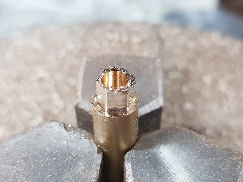 20220416_153642 20220416_153642 by Timothy Froud, on Flickr This looks Brassy, but it's also PB102. The thread is only 2mm long, and everything is pretty thin, so it's better to make it from a strong material.  20220416_222020 20220416_222020 by Timothy Froud, on Flickr The two threaded pieces are a close fit in the recess in the 'Y' piece. I've put a few grooves in the surfaces to aid getting the Silver Solder to flow everywhere in the joint.  20220416_222135 20220416_222135 by Timothy Froud, on Flickr I'm using the usual method of making a ring of 0.5mm Silver Solder wire fitted to each joint, covering the threads etc with Tippex and using plenty of flux. 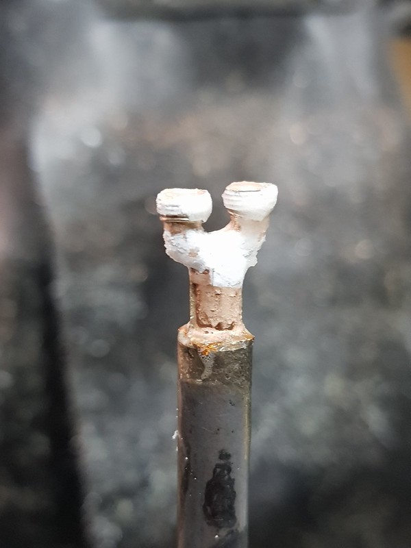 20220417_144747 20220417_144747 by Timothy Froud, on Flickr I'm sure I used a higher melting point Silver Solder for the two halves of the 'Y' piece, but I decided to wire it together to be on the safe side.  20220417_145116 20220417_145116 by Timothy Froud, on Flickr This is held in the 3 jaw chuck on the mill so I can keep it upright. I don't want the threaded parts to tilt over if they become loose when heated.  20220417_145446 20220417_145446 by Timothy Froud, on Flickr That cleaned up nicely in the Ultrasonic tank, wire brush and needle files.  20220417_160110 20220417_160110 by Timothy Froud, on Flickr  20220417_171618 20220417_171618 by Timothy Froud, on Flickr I made a 3D printed fixture to hold it in the Lathe.  20220417_172635 20220417_172635 by Timothy Froud, on Flickr The oversize diameter was turned down to 4mm initially...  20220417_174127 20220417_174127 by Timothy Froud, on Flickr 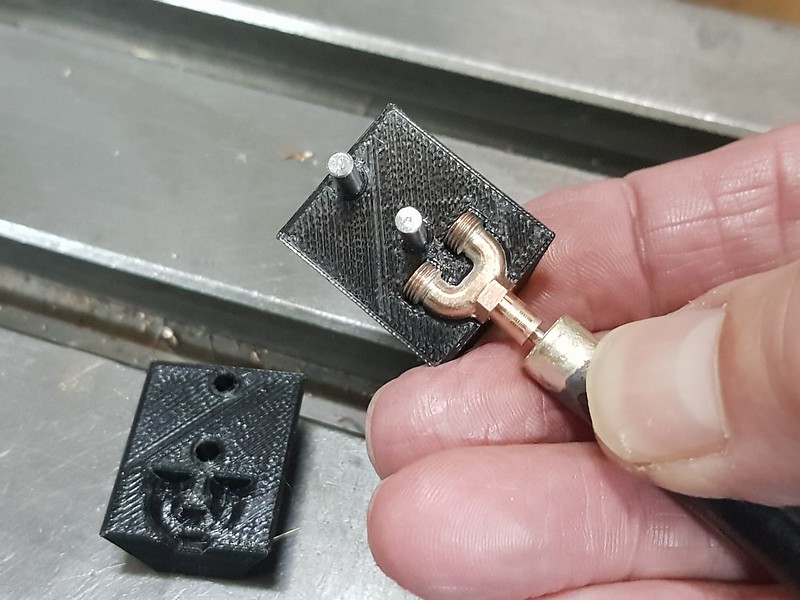 20220417_174336 20220417_174336 by Timothy Froud, on Flickr ... and with it almost parted off, it was clocked in the chuck and cut off. I wanted to keep the long bar so that I could check the runout visually.  20220417_174724 20220417_174724 by Timothy Froud, on Flickr The tailstock die holder was used with an M3.5 die after turning the diameter to 3.5mm  20220417_201409 20220417_201409 by Timothy Froud, on Flickr It was then drilled through and this is how it looks on the manifold. So far, so good. 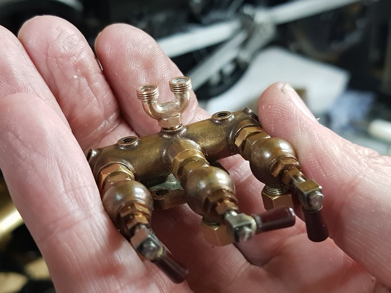 20220417_203955 20220417_203955 by Timothy Froud, on Flickr |
|
JonL
Elder Statesman
 WWSME (Wiltshire)
Posts: 2,911
Member is Online
|
Post by JonL on Apr 17, 2022 21:08:33 GMT
Excellent work. You put a lot of effort into even the smallest parts.
|
|
|
|
Post by Roger on Apr 17, 2022 21:24:09 GMT
Excellent work. You put a lot of effort into even the smallest parts. Thanks Jon. That's were most of the time goes, designing and making these things. Personally, I enjoy doing this stuff, the payoff when it finally works is well worth the effort. These are slightly over scale, but not by much. Even so, they're pretty small. All good fun! |
|
|
|
Post by 92220 on Apr 18, 2022 8:11:55 GMT
Lovely job Roger!!!!! Take the hand away and it could easily be fuillsize!!!
Bob.
|
|
|
|
Post by Roger on Apr 18, 2022 17:56:31 GMT
A quick reminder of what the Whistle Valve assembly looks like.  Whistle valve assembly Whistle valve assembly by Timothy Froud, on Flickr This is one of the Bodies that again is being made from PB102. The full sized item has the two lugs cast as part of the body. It would be a real pain to machine that all from solid, so instead I'm making the lugs separately and Silver Soldering them in place.  20220418_150001 20220418_150001 by Timothy Froud, on Flickr The lugs are only 0.6mm thick, so making them from Brass would leave them very fragile and easily melted during the Silver Soldering process.  20220418_160613 20220418_160613 by Timothy Froud, on Flickr The slots were cut using the Hish Speed Spindle and a 0.5mm PCB burr. The cutter was stepped down 0.05mm (2 thou) per cut. You can't take liberties with this sort of cutter, it's optimised for Glass reinforced PCB material, not metal.  20220418_160629 20220418_160629 by Timothy Froud, on Flickr That was then turned over and the 2.5mm exit hole was added using a 1.5mm End Mill.  20220418_172232 20220418_172232 by Timothy Froud, on Flickr There will be a PB102 fitting for the copper pipe Silver Soldered into this. I'll need to make some sort of 'T' connection between the pipe to the Servo under the Cab floor, and the tiny one that goes to the cosmetic Whistles. The idea is to show a tiny amount of Steam coming out of the cosmetic Whistles, which will also allow the pressure in the Servo valve to drop when the valve is closed. At least, that's how it's supposed to work. |
|
|
|
Post by doubletop on Apr 19, 2022 10:25:02 GMT
On the subject of lining only 1503, 1504 and 1505 were ever lined in BR days, however I agree that they do look more attractive when lined. Martyn Thanks for that Martyn. I'm modelling 1501 as it is in preservation, so it needs to be lined. To be honest, it's going to be a pain to do, but I think it will be worth it. I'm reading this and wondering how you are planning to tackle the lining. As you are always up for a challenge have you considered CNC? You've got the 3D model surely you could set up a tool path and contrive something like a spring loaded lining pen in the Z axis. The tool path could them run over the surface of the part to be lined. You've even got the 4th axis to do the cylinders. That may sound like I'm taking the Mickey but I'm not. Surely it's feasible? Pete |
|
|
|
Post by Roger on Apr 19, 2022 14:18:43 GMT
Thanks for that Martyn. I'm modelling 1501 as it is in preservation, so it needs to be lined. To be honest, it's going to be a pain to do, but I think it will be worth it. I'm reading this and wondering how you are planning to tackle the lining. As you are always up for a challenge have you considered CNC? You've got the 3D model surely you could set up a tool path and contrive something like a spring loaded lining pen in the Z axis. The tool path could them run over the surface of the part to be lined. You've even got the 4th axis to do the cylinders. That may sound like I'm taking the Mickey but I'm not. Surely it's feasible? Pete Hi Pete, Not crazy at all, and Chris Vine has beaten you to this suggestion! Much as I love CNC, I don't think this is going to be practical. if it was just flat plates, and I could perfect it over many attempts, it might be feasible. Unfortunately, some of the lining goes over rivets, and that's a problem for any method. My biggest worry is that the pen would dig in and destroy the surface. I do intend to use the CNC to make the templates for the lines though. |
|
|
|
Post by 92220 on Apr 19, 2022 16:53:58 GMT
Hi Roger.
Doing the lining with templates is a good idea, but getting them exactly right in relation to the previous line, is difficult. As you are producing the guides on the 3D printer, can I suggest you look at a way of drawing up a template locator that all the guides fit to, in the right place, ready for lining, with the template locator held in place with a number of pieces of Blue-Tac. Once Blu-Taced in position, it shouldn't move, but when finally removed, the Blue-Tac will not leave a trace. If the guide holder has a couple of location pins, the templates can just have a couple of accurately placed holes to slip over the pins and hold it in place.
This has made me think a bit more about lining out my loco!! Even without 3D printing, a template locator, and templates, would be relatively easy to make, even with just a vertical mill and no 3D printer. It should then be dead easy lining out with a Bob Moore's lining pen, with well located templates. I shall follow progress with interest!!!
Bob.
|
|
|
|
Post by Roger on Apr 19, 2022 18:17:36 GMT
Hi Roger. Doing the lining with templates is a good idea, but getting them exactly right in relation to the previous line, is difficult. As you are producing the guides on the 3D printer, can I suggest you look at a way of drawing up a template locator that all the guides fit to, in the right place, ready for lining, with the template locator held in place with a number of pieces of Blue-Tac. Once Blu-Taced in position, it shouldn't move, but when finally removed, the Blue-Tac will not leave a trace. If the guide holder has a couple of location pins, the templates can just have a couple of accurately placed holes to slip over the pins and hold it in place. This has made me think a bit more about lining out my loco!! Even without 3D printing, a template locator, and templates, would be relatively easy to make, even with just a vertical mill and no 3D printer. It should then be dead easy lining out with a Bob Moore's lining pen, with well located templates. I shall follow progress with interest!!! Bob. Hi Bob, I'm probably going to CNC machine the templates so that I can make one piece that's fixed in position, and the others can register to it with dowels like you suggest. I don't think 3d printing would be suitable for this because of the difficulty in making registration holes to the required tolerance. Another problem is how long the template would need to be left between the different colours. Obviously you don't want subsequent colours to run into each other, but you also don't want to leave the templates held on with Blue Tac or masking tape for weeks. It's certainly not a trivial thing to get right. |
|
|
|
Post by chris vine on Apr 20, 2022 0:27:17 GMT
I found the best way to register the template was to hinge it on the work with masking tape. Then it can be lifted out of the way to clean up any mistakes and put back in exactly the same position.
You do need some small bits of masking tape on the underside to lift the working edge clear of the surface, otherwise the paint will wick underneath.
This doesn't answer the problem of putting different templates onto the same job for setting further lines inside or outside the first line. To get round that, I made little collars (PTFE or Nylon) which slipped over the lining pen to move it across the correct amount. I think this has fewer chances of errors than using different templates which will have to be accurately made and registered to work...
Chris.
|
|
|
|
Post by Roger on Apr 20, 2022 5:46:21 GMT
I found the best way to register the template was to hinge it on the work with masking tape. Then it can be lifted out of the way to clean up any mistakes and put back in exactly the same position. You do need some small bits of masking tape on the underside to lift the working edge clear of the surface, otherwise the paint will wick underneath. This doesn't answer the problem of putting different templates onto the same job for setting further lines inside or outside the first line. To get round that, I made little collars (PTFE or Nylon) which slipped over the lining pen to move it across the correct amount. I think this has fewer chances of errors than using different templates which will have to be accurately made and registered to work... Chris. Hi Chris, I can see how that would work, I might well use that idea. How long would you leave it between colours? I presume you need to leave it a day or two at the least. The issue is then, what happens when you mess up? |
|
|
|
Post by chris vine on Apr 20, 2022 7:18:21 GMT
Hi Roger,
I can't remember exactly, but I expect it was at least a week between colours. Probably in my warm box at around 30 to 40 C.
I would have run a test line on an old test piece of metal to make sure that the line really was bomb proof before tackling the next line!!
By bomb proof, I mean that you can run a cotton bud, just moistened with white spirit, over the line without taking it off.
Maybe more important is that the gloss on the panel is really cured. I think I probably left Bongo's tender in the warm box for a month before risking doing the lining.
Then, if you make a mistake you can take the whole line off and start again!!
Chris.
|
|
|
|
Post by 92220 on Apr 20, 2022 8:48:47 GMT
Hi Roger.
CNC sounds the way to go. I just didn't know what accuracy 3D printing gives. As far as time to leave between lining colours, it is not long. The lining paint should be touch dry in around 2 - 2.1/2 hours. The paint only needs to be touch dry, not fully cured. This also means that if you have made a mistake, the paint can be removed with white spirit or turps substitute, without effect on the main loco paint, if that is the base solvent for the lining colours. Actually Blue-Tac should be safe to leave for up to a month, without ill effect, as long as the paint coat it is in contact with, is fully cured. If masking tape is used, that shouldn't be left sticking to the loco for more than around 2 to 4 hours, otherwise the adhesive can begin to transfer to the paint surface, depending on the brand of masking tape. A warm atmosphere can also make this problem worse, so experimenting might be worth doing, depending on what products you intend to use.
Chris's system above will work well. You must be able to remove a mistake, though, without effecting the previous line, or main paint coat, so timing is important. And that depends on the products used.
Bob.
|
|
|
|
Post by chris vine on Apr 20, 2022 9:12:28 GMT
That is why I suggest leaving each line for something like a week, so that it will withstand removing a neighbouring line if you muck it up!!
Chris.
|
|
|
|
Post by Roger on Apr 20, 2022 9:29:14 GMT
All great advice, copied into my notes for future reference. I'll need to experiment with my blunt syringe needles to see how this works out.
|
|
|
|
Post by 92220 on Apr 20, 2022 14:17:25 GMT
Hi Roger.
With the needles, you may need to experiment with a fine wire up the middle, to help with the flow. It all depends on the viscosity of the lining paint. This is how the old UNO draughtsman's pens worked. In fact my Rotring pen set also has a wire up the middle of each nib as well.
Bob.
|
|
|
|
Post by Roger on Apr 20, 2022 18:41:33 GMT
Hi Roger. With the needles, you may need to experiment with a fine wire up the middle, to help with the flow. It all depends on the viscosity of the lining paint. This is how the old UNO draughtsman's pens worked. In fact my Rotring pen set also has a wire up the middle of each nib as well. Bob. Thanks for that Bob, I've got some Florist's wire that might be good for that. |
|


