|
|
Post by Cro on Sept 15, 2022 12:54:10 GMT
Hi Roger, Chris’s comment brings back memories! Youngest sone was driving my loco…. Under instruction, he had been doing a great job. Then the film crew turned up! Suitably sidetracked at the station with injector on…… you can see we’re this is going! By the time I spotted it the boiler must of been all but fill! Made sure the cylinder drains were open, gingerly opened the regulator…….. lovely fountain of hot water up the chimney, hot water out the drains! A slow trip, with fountain & cylinder drains slowly decreasing! Luckily no damage! Well to the loco! Pride some what damaged! Cheers Kerrin Hi Kerrin, It's so easily done, I've forgotten to turn an injector off more than once. Fortunately it's not been enough to prime... yet! We have all done it! |
|
|
|
Post by Roger on Sept 15, 2022 21:44:06 GMT
Just in case you've never seen what's inside of one of these Relief Valves, here's a picture kindly sent by someone. As usual, I can't remember who that was, but thank you for that. As you can see, the slot in the end of the adjusting screw is pretty small...  Possibly similar to 1501s Possibly similar to 1501s by Timothy Froud, on Flickr ... so my 0.5mm cutter is way over scale for that unfortunately. I recently bought some proper short fluted ones from eBay which ought to make this less painful. They're not overly expensive, so I bought a few to see if they hold up well. I've got some PCB cutters, but they have really long flutes and are very fragile. Here I'm using the High Speed Spindle and 2mm/min feedrate with 0.01mm depth of cut. It's going to take an hour and twenty minutes for each one, but I'd rather do that than keep breaking cutters.  PXL_20220915_204351516 PXL_20220915_204351516 by Timothy Froud, on Flickr |
|
|
|
Post by Roger on Sept 17, 2022 20:20:08 GMT
Here are the four sets of parts for the finished Relief Valves. You can see that the little adjusters have to be screwed into the body from the inside, but there's a problem because they're too low to easily get hold of them to do that.  PXL_20220917_092119481 PXL_20220917_092119481 by Timothy Froud, on Flickr Rather than struggle, I used a small blob of Blue Tac on the end of a rod and used that as a screw driver. That worked surprisingly well. Once started, the screw could be wound backwards using a jeweller's screwdriver.  PXL_20220917_140947518 PXL_20220917_140947518 by Timothy Froud, on Flickr Then it was just a matter of setting the pressure to about 150PSI using the hydraulic pump...  PXL_20220917_140641638 PXL_20220917_140641638 by Timothy Froud, on Flickr ... and fitting them to the Cylinder Covers.  PXL_20220917_143912901 PXL_20220917_143912901 by Timothy Froud, on Flickr One more job ticked off. |
|
JonL
Elder Statesman
 WWSME (Wiltshire)
Posts: 2,911
|
Post by JonL on Sept 18, 2022 15:43:20 GMT
Fantastic work.
|
|
|
|
Post by martyn1936 on Sept 18, 2022 17:34:49 GMT
Excellent job as always. It is interesting that you chose to set them to 150 psi. When I was making mine I thought about the setting quite a lot and I came to the conclusion that they could be set quite close to the boiler pressure. If the engine had a hydraulic lock the pressure would rise extremely quickly so the earlier the relief valves opened the better and as the cylinders do not work at boiler pressure I didn't see a problem. My boiler works at 100 psi and I set mine to 110 psi. I haven't run the engine yet so I don't know if it's right, time will tell.
Martyn
|
|
|
|
Post by Roger on Sept 18, 2022 22:29:53 GMT
Excellent job as always. It is interesting that you chose to set them to 150 psi. When I was making mine I thought about the setting quite a lot and I came to the conclusion that they could be set quite close to the boiler pressure. If the engine had a hydraulic lock the pressure would rise extremely quickly so the earlier the relief valves opened the better and as the cylinders do not work at boiler pressure I didn't see a problem. My boiler works at 100 psi and I set mine to 110 psi. I haven't run the engine yet so I don't know if it's right, time will tell. Martyn Hi Martyn, I don't see the need to set them that close to the working pressure. The pressure will certainly rise quickly to whatever it takes to open the valves. As long as that's not so high as to damage anything then all should be well. I wanted to avoid any issues with leakage so I thought it best to set them on the high side. It's worth mentioning that when I say that I set them to 150PSI, that was bumping them with the hand pump hard to make them lift well off the seat. They start to lift before that, something around 120PSI. However, a small flow isn't going to help if it needs to release a lot of water. So my 150PSI is basically a similar idea to the boiler Accumulation test where you're interested in the maximum pressure that you'll ever achieve. |
|
|
|
Post by Shawki Shlemon on Sept 22, 2022 8:14:28 GMT
In Australia , a steam test is carried out by boiler inspector prior to certification , with full fire box , full blower and full boiler , the safety valves must lift to relief pressure and the gauge shall not exceed boiler design by more than 10% . for example ,100 psi boiler ( that is maximum allowed ) the pressure gauge should not read more than 110 psi at any time . I don't know what you do in UK .
|
|
|
|
Post by Roger on Sept 22, 2022 8:42:04 GMT
In Australia , a steam test is carried out by boiler inspector prior to certification , with full fire box , full blower and full boiler , the safety valves must lift to relief pressure and the gauge shall not exceed boiler design by more than 10% . for example ,100 psi boiler ( that is maximum allowed ) the pressure gauge should not read more than 110 psi at any time . I don't know what you do in UK . Hi Shawki, it's good to hear from you! I think that's how the test is performed here too, it certainly makes sense. |
|
|
|
Post by ettingtonliam on Sept 22, 2022 14:15:08 GMT
Are we somehow mixing the requirements for boiler safety valves, which do form part of the steam test, with cylinder relief valves which are not?
|
|
|
|
Post by Roger on Sept 22, 2022 21:23:07 GMT
Are we somehow mixing the requirements for boiler safety valves, which do form part of the steam test, with cylinder relief valves which are not? I just make the analogy in the manner that it needs to work to make it effective, it's not a legal requirement. I suggested that what matters with a cylinder relief valve is that it opens fully at a given pressure, rather than the pressure that it starts to open. A piston slamming into a plug of water is going to send the pressure up immensely. You need a big enough passage to open sufficiently to keep that pressure from breaking anything. You could have a tiny valve that starts to open at 100PSI and that would be hopeless compared to a large one that opens fully at 150PSI. It's the volume and pressure that matters, hence me jerking the hand pump against the valve so I can see that it fully opens at a reasonable pressure. |
|
|
|
Post by Roger on Sept 25, 2022 20:42:31 GMT
I'm currently working on finishing the Oil Pipes from the Lubricating Boxes on the Crosshead and Expansion Link bearings. There are a couple of M1.6 nuts and bolts that are a pain to get to because they are too close to the body of the Lubricating Box to get my normal Box Spanner on. So here I'm making two skinny 2.5mm AF Box Spanners from a piece of 1/8" Silver Steel which just gives enough meat around the outside. This is one of those 0.5mm Carbide Cutters I recently bought from China.  PXL_20220925_164637149 PXL_20220925_164637149 by Timothy Froud, on Flickr That worked out very nicely.  PXL_20220925_164851843 PXL_20220925_164851843 by Timothy Froud, on Flickr I've managed to shear off the Florist's Wire inside one of these, I guess they were pinched where that corner needs to be a very tight radius. Now, I could make another one, the second one came out without any issues, but I thought I'd dissolve the wires with Alum because I've never done that before. So I've ordered some Alum and made an adaptor for the Oil Can so that I can prove that it's clear when it's done. I also thought this was a useful thing to have to make sure the various pipes have a reasonable flow without too many restrictions. The adaptor uses an M2.5 bolt cut down and drilled through with a 0.6mm Carbide PCB drill to 9mm deep. Taken gently and withdrawing the drill every half millimeter gets this done without any drama. The main thing is not to run into the bottom of the hole with each peck. This is where the Tailstock DRO comes into its own.  PXL_20220925_200621891 PXL_20220925_200621891 by Timothy Froud, on Flickr The Oil Can has an M4.5 Coarse Thread, so I've also made an adaptor to use with my Air Line so I can blow it through and also force anything else that I need to get through the pipes. ] 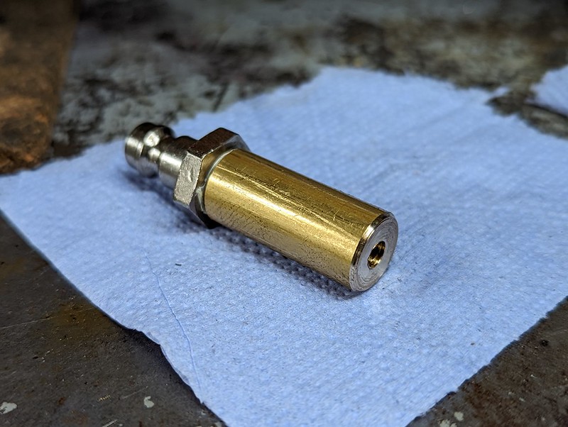 PXL_20220925_202338528 PXL_20220925_202338528 by Timothy Froud, on Flickr |
|
|
|
Post by ettingtonliam on Sept 26, 2022 1:44:12 GMT
I thought alum worked for dissolving steel in a non ferrous surround (tap boken off in gunmetal casting). Does it work for iron in a steel surround?
|
|
|
|
Post by Roger on Sept 26, 2022 6:29:16 GMT
I thought alum worked for dissolving steel in a non ferrous surround (tap boken off in gunmetal casting). Does it work for iron in a steel surround? You're right, it's a Copper pipe with an Iron wire stuck in it. |
|
|
|
Post by ettingtonliam on Sept 26, 2022 9:00:24 GMT
My mistake. I thought somehow you'd got the wire stuck in one of the tiny box spanneers.
|
|
jem
Elder Statesman
Posts: 1,066
|
Post by jem on Sept 26, 2022 10:39:24 GMT
does the alum then dissolve the steel? and if so it could loosen steel in steel if treated very gently. what about HSS in steel, ie a tap in a steel hole? lots of questions but hopefully very interesting answers please.
best wishes
Jem
|
|
|
|
Post by Roger on Sept 26, 2022 17:42:44 GMT
does the alum then dissolve the steel? and if so it could loosen steel in steel if treated very gently. what about HSS in steel, ie a tap in a steel hole? lots of questions but hopefully very interesting answers please. best wishes Jem Hi Jem, Those are interesting questions. HSS clearly dissolves in Alum because that's what it's often used for. I suppose it might loosen a HSS tap in Steel so that you could carefully wind it out. My preferred solution is to set up the mill as centrally as possible and then use a Carbide cutter of some kind to gingerly turn the centre of the broken tap to dust. It takes time, but it's not destructive. |
|
|
|
Post by Roger on Sept 26, 2022 21:47:02 GMT
The Oil feed to the main Crosshead goes through the Crosshead Slidebar on the real thing, so this does too. On the full sized locomotive, there's a gland, but I've made that a dummy that the pipe just slides through.  PXL_20220926_144332736 PXL_20220926_144332736 by Timothy Froud, on Flickr  PXL_20220926_144306046 PXL_20220926_144306046 by Timothy Froud, on Flickr  PXL_20220926_143915602 PXL_20220926_143915602 by Timothy Froud, on Flickr It's fiddly to get both oil pipes into their respective holes, but it is possible. Hopefully this won't have to come off again. If the Cylinder comes off, the whole thing, including the Crosshead Guide Bar will come off too. |
|
|
|
Post by Roger on Sept 28, 2022 9:16:08 GMT
There are actually two oil boxes on the Gear Frame on 1501, but I didn't spot the front one until recently. As it happens, there isn't room on the inside for the front one anyway because the Expansion Link rocks too far forward. On the real thing, the front one feeds the Expansion Link bearings, and the rear one feeds the Weigh Shaft ones. On my design, there's only one bearing on the outside of the Gear Frame for the Weighshaft, and frankly it doesn't move enough to warrant an oiler. So I've opted to feed the Expansion Link bearings from the rear Oil Box instead since it would benefit the most from that. The oil pipe looks unsightly from this side, but you won't see it at all on the finished locomotive when the Boiler and Pannier Tanks are in the way. I've added the drill way into the outside of the bearing and fed the pipe down the outside because that's the way the connection comes out of the Oil Box. Timothy Froud, on Flickr  PXL_20220927_202215522 PXL_20220927_202215522 by Timothy Froud, on Flickr The outside Expansion Link bearing has the oil hole on the inside of the Gear Frame. The pipe clears the arm on the Weighshaft but the lug on the Oil Box might just touch. I'll wait an see if that's the case when it's all assembled to the Reverser because it might not be quite at the extreme end of the Weighshaft Arm travel. Either way, it would barely need any relief as it only just touches.  PXL_20220927_210038614 PXL_20220927_210038614 by Timothy Froud, on Flickr I need to conduct some experiments to see how oil drops off the end of the 1.6mm diameter Oil pipes. I know that a chamfer on the outside prevents a large enough drop forming to drop off. I don't know whether a flat end or internal chamfer would allow the oil to drip from the open end. Bear in mind that the oil is 680 grade, so it's pretty thick. It will probably be touching the bottom of the pockets they're delivering the oil to, but in case they're not, it would be better if they just fed a drop from the open end. |
|
uuu
Elder Statesman
your message here...
Posts: 2,814
|
Post by uuu on Sept 28, 2022 9:35:43 GMT
I'm imagining, with no testing to back this up, that cutting the pipe off at an angle would encourage the drop to release from the pointed tip.
Wilf
|
|
|
|
Post by Roger on Sept 28, 2022 14:41:48 GMT
I'm imagining, with no testing to back this up, that cutting the pipe off at an angle would encourage the drop to release from the pointed tip. Wilf Good idea Wilf, something else to test. |
|


