|
|
Post by Roger on Feb 5, 2023 21:38:15 GMT
Ok, back to the semi-scale Whistle Valves that I've been agonising over. This is what they should look like...  20180110_111622 20180110_111622 by Timothy Froud, on Flickr ... and here are the new internals. The last time I showed this, it had 2.5mm Silicon Nitride balls, but I couldn't get it to seal. It's so tiny, that the slightest imperfection makes it weep. So I've redesigned the valve element to use the tiny O-rings that I had made years ago when I was going to feed the pocket under the axleboxes with oil. There was going to be an O-ring at the split, but I changed my mind and didn't do that in the end. So I've got 200 0.5mm section O-rings with a 1mm hole going begging, and this seemed like an ideal place to use them. I could have made a conical PTFE insert, that's what I originally planned. However, it's very small and difficult to make, and this seemed easier and probably more satisfactory.  Sectioned valve with O-ring valve Sectioned valve with O-ring valve by Timothy Froud, on Flickr This is how that looks on the 'Y' piece for the pressure test. 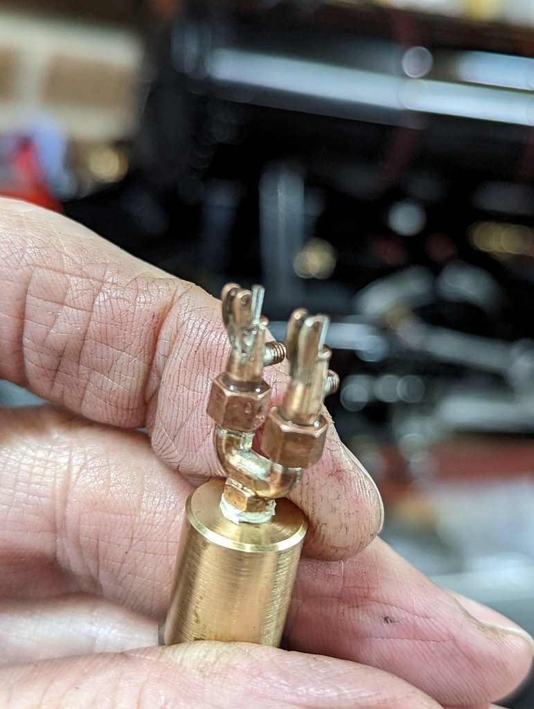 PXL_20230205_205916893 PXL_20230205_205916893 by Timothy Froud, on Flickr The shaft is made from 3mm Stainless Steel rod.  Valve spindle Valve spindle by Timothy Froud, on Flickr That needed a 0.5mm wide parting tool for the O-ring groove, and something rough and ready isn't going to be good enough.  PXL_20230205_123422564 PXL_20230205_123422564 by Timothy Froud, on Flickr This is probably the least used piece of Workshop equipment, but I'd never part with it. Sometimes, it's the perfect machine for the job.  PXL_20230205_123418920 PXL_20230205_123418920 by Timothy Froud, on Flickr I'm a big fan of this Lathe Tool, it's one of the best things I've bought recently. It can be made razor sharp, and being pointy, you can keep the cutting forces to an absolute minimum. It's great where you need to make a sharp corner. I'm only roughing this out on the Lathe, it's too long and slender to turn without supporting the end, and that's harder to do than grinding it. You can't just turn a 10mm length of Stainless Steel down to 1.3mm by going along the whole length, it's going to end up massive at the unsupported end and probably climb up over the tool. Here I've done the first 1.5mm to 1.3mm diameter and just completed the second 1.5mm to give 3mm length at this point and starting the next 1.5mm. I'm only taking 0.2mm cuts each time.  PXL_20230205_201057277 PXL_20230205_201057277 by Timothy Froud, on Flickr Gradually working along like that gets you here, where the 0.5mm O-ring groove is going in. Note that I'm using 3mm Stainless Steel rather than 2.5mm because it gives more support while being turned.  PXL_20230205_125309382 PXL_20230205_125309382 by Timothy Froud, on Flickr The register for the Spring was then added on the back.  PXL_20230205_202501967 PXL_20230205_202501967 by Timothy Froud, on Flickr This is how I set the Grinder to cut parallel. I just clock up and grind a length of Brass, take a small cut and check the diameter at each end. The table can be swivelled to correct the error. 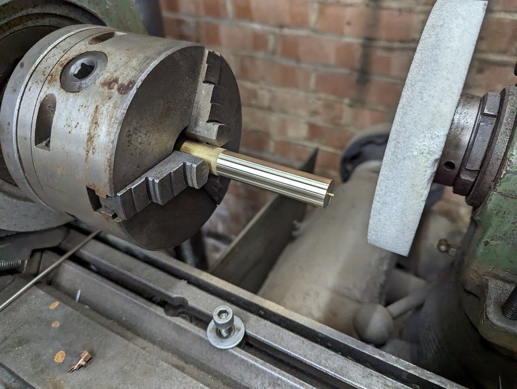 PXL_20230205_155057598 PXL_20230205_155057598 by Timothy Froud, on Flickr The wheel was trued up on the side and face, and then the diameter was brought to size... 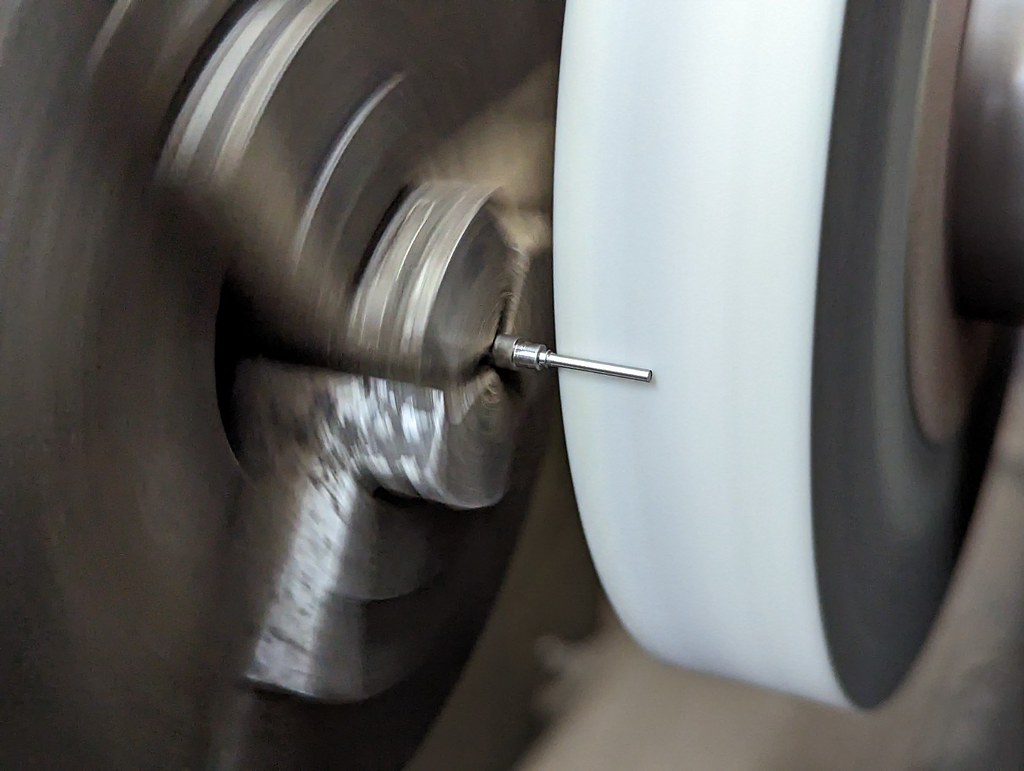 PXL_20230205_160328656 PXL_20230205_160328656 by Timothy Froud, on Flickr ... so it fitted the body.  PXL_20230205_160407771 PXL_20230205_160407771 by Timothy Froud, on Flickr  PXL_20230205_161904181 PXL_20230205_161904181 by Timothy Froud, on Flickr I turned up a small Brass tool to aid getting the O-ring over the sharp flange.  PXL_20230205_163446666 PXL_20230205_163446666 by Timothy Froud, on Flickr 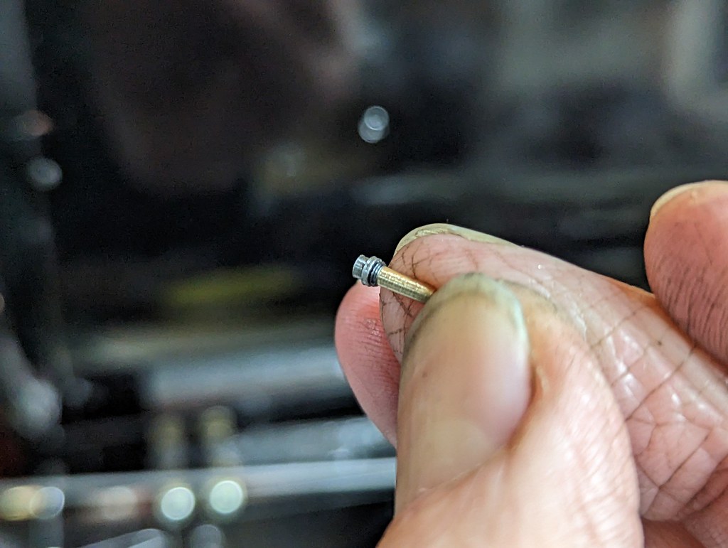 PXL_20230205_204556001 PXL_20230205_204556001 by Timothy Froud, on Flickr 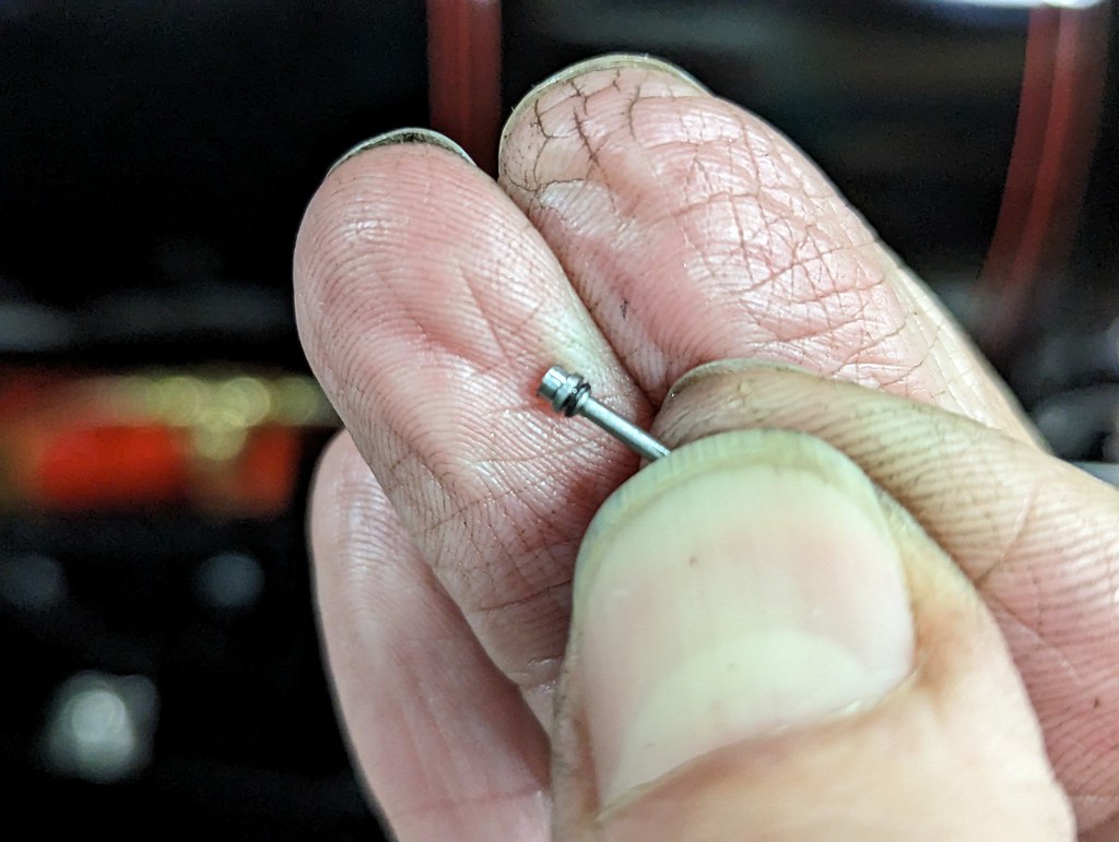 PXL_20230205_163529908 PXL_20230205_163529908 by Timothy Froud, on Flickr The O-rings are the smallest ones I've used on the Locomotive. 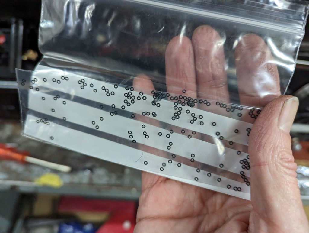 PXL_20230205_205538857 PXL_20230205_205538857 by Timothy Froud, on Flickr Anyway, I'm delighted to say that these work really well, without any leakage. I was beginning to wonder if these were going to be an ongoing source of annoyance, but I think this is going to be a solid solution. I've still got to tidy up the top ends of the shafts so that they engage with the actuating levers. I need to get on and make those before I can do that though. So far, so good. |
|
|
|
Post by steamer5 on Feb 5, 2023 21:50:59 GMT
Hi Roger,
Nice work!
Cheers Kerrin
|
|
|
|
Post by Roger on Feb 6, 2023 21:21:59 GMT
This is the arrangement for actuating the Whistles. The LH one looks like it's intended to be used from either side of the Cab. The one on the right looks like it's only intended for use from the RH side. Maybe someone can remind me which is the high and which is the low tone and what they signify. I'm sure I've been told this before, but I can't see it in my notes.  20180110_111421 20180110_111421 by Timothy Froud, on Flickr The levers are made from 1mm thick Gauge Plate so that they don't bend as easily. Here I'm using a 1.5mm Carbide cutter going 0.5mm deep per cut and doing a finishing pass of 0.2mm I've already drilled the 1mm holes for the chain and pivot. Ideally these would be something that doesn't rust, but Stainless Steel is going to look wrong. I'll black them and use a preservative. The pivot pins will be Stainless Steel. 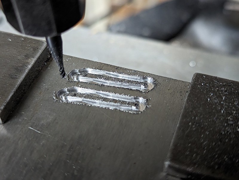 PXL_20230206_170126939 PXL_20230206_170126939 by Timothy Froud, on Flickr It's always a good sign when the back is deformed like this between the nibs. It's fairly easy to break them out and tidy them up without too much of a struggle. 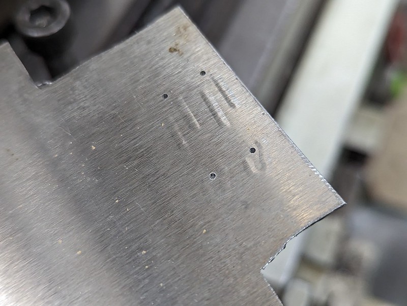 PXL_20230206_170237176 PXL_20230206_170237176 by Timothy Froud, on Flickr I'll Black them when I know everything works properly. 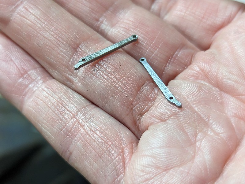 PXL_20230206_210859710 PXL_20230206_210859710 by Timothy Froud, on Flickr |
|
jma1009
Elder Statesman

Posts: 5,901
|
Post by jma1009 on Feb 6, 2023 23:23:08 GMT
Having made a reasonably scale GWR double whistle valve many years ago I would make a few comments. I've never made a whistle valve without a lever made of stainless steel (and I've made quite a few), and the choice of gauge plate seems rather an odd choice.
I've been quite lucky in getting mine to seat ok. But it can be a problem on an hydraulic test further years hence. So for Stepney the whistle valve is a screw in fitting into the turret/fountain so has the facility to be removed and blanked off.
The days of pumping up continuously on an hydraulic test to overcome a leak on a whistle valve that was suspected to be the cause of a drop in pressure during the test have long gone.
|
|
|
|
Post by Roger on Feb 7, 2023 10:04:58 GMT
Having made a reasonably scale GWR double whistle valve many years ago I would make a few comments. I've never made a whistle valve without a lever made of stainless steel (and I've made quite a few), and the choice of gauge plate seems rather an odd choice. I've been quite lucky in getting mine to seat ok. But it can be a problem on an hydraulic test further years hence. So for Stepney the whistle valve is a screw in fitting into the turret/fountain so has the facility to be removed and blanked off. The days of pumping up continuously on an hydraulic test to overcome a leak on a whistle valve that was suspected to be the cause of a drop in pressure during the test have long gone. Hi Julian, If you look at the photo of 1501, the whole assembly is pretty much black. The Bronze valve will hopefully take on a dark hue, and I'll Black the lever. The problem with Stainless is that it's shiny, and that's not going to look right. If corrosion proves to be an issue, I may try to Black Nickel plate it instead. I know it's only a small detail, but I'd like it to look as close to the real thing as possible. The 'Y' piece can be unscrewed from the Turret if necessary for the Hydraulic test, but hopefully it will seal anyway. We'll see. |
|
|
|
Post by jon38r80 on Feb 8, 2023 13:03:56 GMT
For someone with failing eyesight, you realy set youself some challenges. If you are like me there are quite fet of those tiny bits hidden about your workshop. amazing detail as usual.
|
|
|
|
Post by Roger on Feb 8, 2023 21:58:23 GMT
If you go back a few posts, you'll see that the whistle valves have a spring wire arrangement that returns the arm to the down position. It's also used to stop the pivot pins from coming out. This is all very fiddly, but a solution needs to be found, and it seems logical to try to copy the original if at all possible. So here is a 1mm diameter Stainless Steel pin having a 0.5mm wide groove added 0.25mm from the end to locate the spring. I'm using a Pin Chuck, even though I hate these things. It's an Eclipse one, and it's frankly garbage. However, it's all I've got so I'm holding it on the knurled part to prevent it trying to climb over the parting tool. Yes, it could potentially unscrew, but that's less of a risk than having a large overhang.  PXL_20230208_205840779 PXL_20230208_205840779 by Timothy Froud, on Flickr Anyway, here those are, and that looks like it will work as long as I can make a spring that looks right.  PXL_20230208_214822583 PXL_20230208_214822583 by Timothy Froud, on Flickr |
|
|
|
Post by andrewtoplis on Feb 8, 2023 23:19:35 GMT
Roger, it's a guess but the high tone 'warning' whistle is likely to be the one with a chain for either side, just incase the fireman needs it too. The low tone 'brake' whistle, an odd GW tradition, would be more likely to be the right hand side only one, as all GW locos were right hand drive
|
|
jma1009
Elder Statesman
Posts: 5,901
|
Post by jma1009 on Feb 9, 2023 0:50:47 GMT
Stainless can always be blackened if required by a permanent marker pen.
|
|
uuu
Elder Statesman
your message here...
Posts: 2,810
|
Post by uuu on Feb 9, 2023 8:33:56 GMT
Roger, it's a guess but the high tone 'warning' whistle is likely to be the one with a chain for either side, just incase the fireman needs it too. The low tone 'brake' whistle, an odd GW tradition, would be more likely to be the right hand side only one, as all GW locos were right hand drive Looking at some pictures of GWR locos, the larger whistle appears to be mounted to the right, which would support this theory. Wilf |
|
davidk
Active Member

Posts: 32
|
Post by davidk on Feb 9, 2023 10:35:49 GMT
Hi Roger,
Regarding holding small diameter workpieces in the lathe, I use a parallel shank ER16 collet holder. Arc Euro Trade are one supplier, their part number is 050-110-16550. That, combined with a set of ER16 collets, gives work holding diameters from 0.5mm to 10mm. The collet holder can then be held in a 3-jaw, 4-jaw or ER32/ER40 collet etc. Holding it in the 4-jaw of course gives the opportunity to accurately centre the work piece.
No connection with Arc Euro Trade, just a very satisfied customer.
On one of my ER16 collet holders, I cut the shank down by about half to reduce overhang when held in a collet. I also drilled 6mm diameter all the way through to allow for holding longer stock.
I also use a similar system on my mill to hold small diameter drills and cutters. One benefit from this is much greater visibility due to the small dimensions of the ER16 collet holder. Another is accessibility in tight spaces.
Hope this is of interest
David
|
|
|
|
Post by Roger on Feb 9, 2023 16:36:30 GMT
Hi Roger, Regarding holding small diameter workpieces in the lathe, I use a parallel shank ER16 collet holder. Arc Euro Trade are one supplier, their part number is 050-110-16550. That, combined with a set of ER16 collets, gives work holding diameters from 0.5mm to 10mm. The collet holder can then be held in a 3-jaw, 4-jaw or ER32/ER40 collet etc. Holding it in the 4-jaw of course gives the opportunity to accurately centre the work piece. No connection with Arc Euro Trade, just a very satisfied customer. On one of my ER16 collet holders, I cut the shank down by about half to reduce overhang when held in a collet. I also drilled 6mm diameter all the way through to allow for holding longer stock. I also use a similar system on my mill to hold small diameter drills and cutters. One benefit from this is much greater visibility due to the small dimensions of the ER16 collet holder. Another is accessibility in tight spaces. Hope this is of interest David Hi David, This is a very good idea, one that I'll probably follow up on. I bought a 2-1mm ER32 collet, but there's no way it's ever going to go much below 2mm because the slits aren't wide enough. Edit... I've just ordered this 20mm diameter Parallel shank ER16 collet chuck and this ER16 collet set from eBay. I decided on the 20mm shank instead of the larger and more rigid 25mm one because I can only fit 20mm in my ER32 collet, and that might prove to be a useful way of holding it. I've often thought it would be handy to have something like this for use with the 4th axis. The ER32 collet arrangement I've used is a bit too bulky for the really fiddly work where the tools are really short. |
|
|
|
Post by 92220 on Feb 11, 2023 12:14:21 GMT
Hi Roger. Definitely fiddly work!!!! Well done. If you want a collet that will tighten down to 0.5mm, these people can supply:- littlemachineshop.com/info/er_collet_sizes.phpThey can supply collets to fit the ER11 and ER16 chucks. Bob. |
|
|
|
Post by Roger on Feb 11, 2023 12:31:27 GMT
Hi Roger. Definitely fiddly work!!!! Well done. If you want a collet that will tighten down to 0.5mm, these people can supply:- littlemachineshop.com/info/er_collet_sizes.phpThey can supply collets to fit the ER11 and ER16 chucks. Bob. Thanks Bob, It looks like the standard set I've ordered goes down to 0.5mm, so hopefully that's the case. If not, I'll get one from there. |
|
|
|
Post by Roger on Feb 12, 2023 17:29:42 GMT
Continuing the quest to make the semi-scale Top Feed Clacks seal, I tried the ground PTFE ball on the left, but that didn't seal completely when cold and at a low pressure. It may well seal when it's hot and the pressure is high, but it might also deform and then not seal when it moves to a different position. Flushed with the success of the O-ring seal on the Whistle Valve, I thought I'd give that a try on this too. There's nothing to lose since you can go back to a ball at any time. 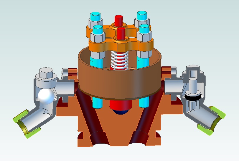 Sectioned safety valve and top feed Sectioned safety valve and top feed by Timothy Froud, on Flickr I've elected to support the top as well as have a guide on the bottom because it could easily jam if it had just one or the other. Obviously the two guides need to be concentric and enough clearance is required to make sure it can seat properly. I might need to put a small O-ring on the top location to restrict the travel because it could almost come out of the bottom location. 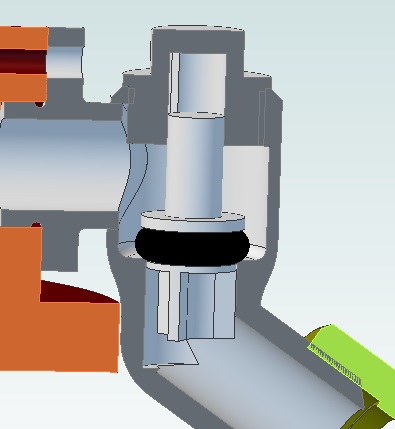 O-ring type top feed clack O-ring type top feed clack by Timothy Froud, on Flickr Anyway, the bottom location was machined first while I could still get hold of it... 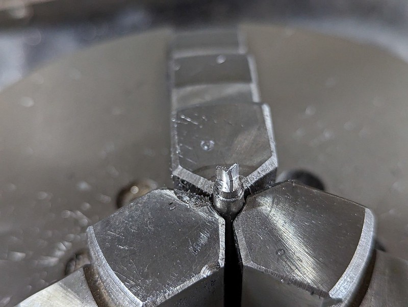 PXL_20230211_195342005 PXL_20230211_195342005 by Timothy Froud, on Flickr ... then the O-ring location was added...  PXL_20230211_200110726 PXL_20230211_200110726 by Timothy Froud, on Flickr ... and the parting tool was plunged almost to depth from right to left in stages so there was the maximum amount of material supporting it. The final cut was taken right to left, tidying up the flange to length at the same time. This is how I do all of these LH turned features.  PXL_20230211_201442125 PXL_20230211_201442125 by Timothy Froud, on Flickr The caps had 1mm holes added first...  PXL_20230211_205748486 PXL_20230211_205748486 by Timothy Froud, on Flickr ... then the centre hole was machined. I've actually made the two 1mm holes a bit too far apart, and they've bruised the outside of the hex in places. i'll probably need to make those again later. 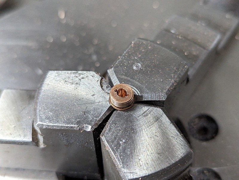 PXL_20230211_214252016 PXL_20230211_214252016 by Timothy Froud, on Flickr 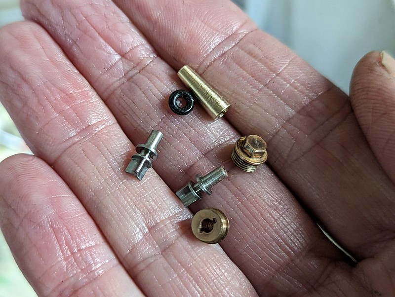 PXL_20230212_121559753 PXL_20230212_121559753 by Timothy Froud, on Flickr Fitting the O-ring is tricky when it has to be stretched so much, so a tapered sleeve makes that easy.  PXL_20230212_145454855 PXL_20230212_145454855 by Timothy Froud, on Flickr  PXL_20230212_121744778 PXL_20230212_121744778 by Timothy Froud, on Flickr Initially this didn't seal, so I checked the depth of the 4mm bottom hole, and it's not deep enough.  PXL_20230212_144412236 PXL_20230212_144412236 by Timothy Froud, on Flickr 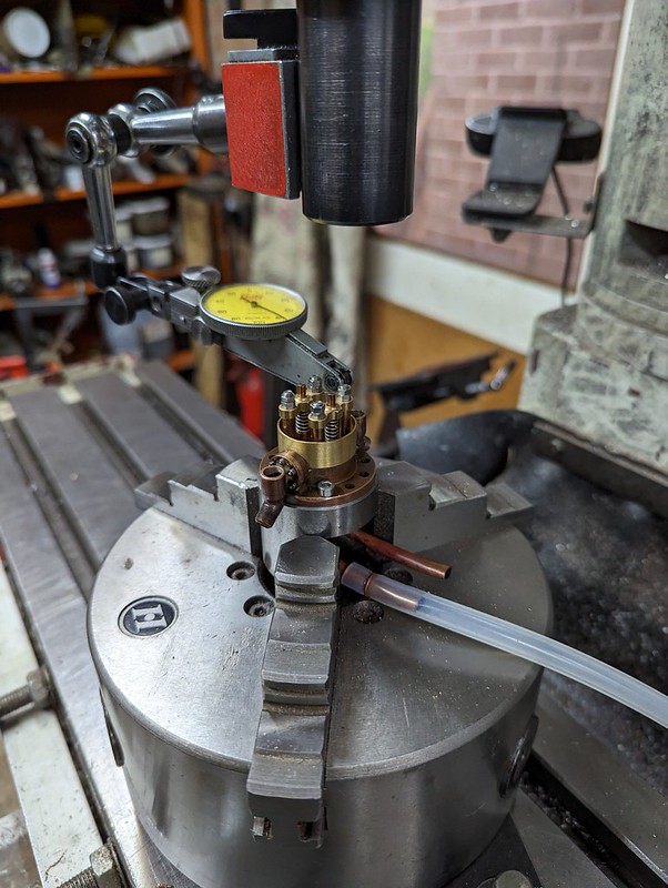 PXL_20230212_144302785 PXL_20230212_144302785 by Timothy Froud, on Flickr It's been drilled deep enough, but the reamer hadn't been put through as deep as it could have been because that didn't matter with a ball for the valve. 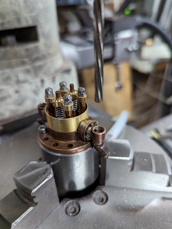 PXL_20230212_143911159 PXL_20230212_143911159 by Timothy Froud, on Flickr That's done the trick and it seals nicely now. I can't be doing with it being a nuisance, leaking and just being annoying. I need a solid solution, and hopefully this will be ok in practice. We'll see. After a trial fitting without the O-ring, here it is finally in place. The O-ring seals on the inside diameter of the boiler bush, there's no need for a gasket and the bolts as only done up lightly but evenly to make sure they share the same load. They just stop the fitting from moving, they play no part in the sealing. 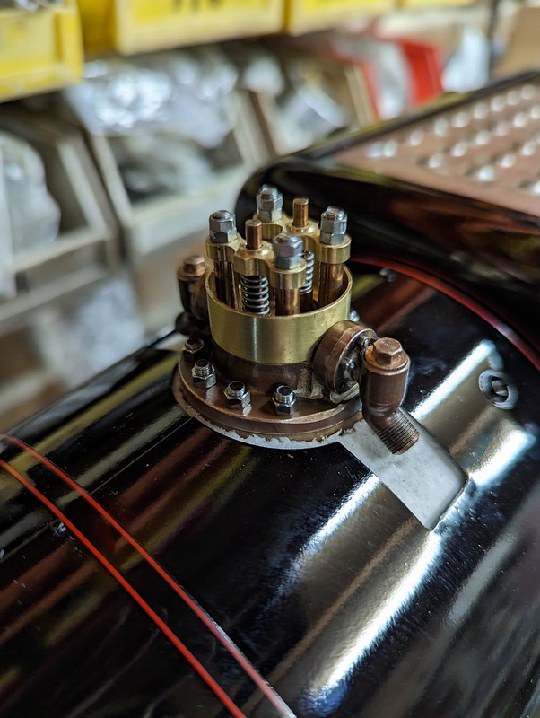 PXL_20230212_151854524 PXL_20230212_151854524 by Timothy Froud, on Flickr A quick sanity check to make sure it all still clears the Bonnet. I need to rivet on the shoulders and then that just needs the dummy flange bolts before it's painted. I'll just paint the shoulders since that's how it is in preservation. 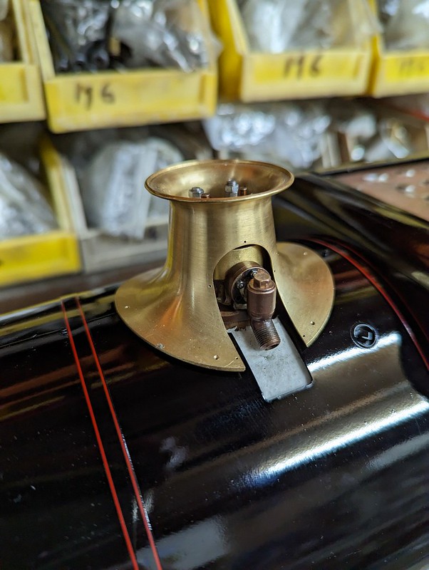 PXL_20230212_151906866 PXL_20230212_151906866 by Timothy Froud, on Flickr |
|
|
|
Post by Roger on Feb 13, 2023 21:02:16 GMT
The Safety Valve Bonnet on 1501 is bolted onto the cladding with six bolts and washers.  IMG_1414 IMG_1414 by Timothy Froud, on Flickr These are obviously Steel, but the only M1 bolts I can get are Brass, so that's not going to look right. So here's a 3mm piece of Mild Steel being machined to make dummy bolts.  PXL_20230213_113122361 PXL_20230213_113122361 by Timothy Froud, on Flickr The hex was tidied up with a file to add the chamfer, the flange to simulate the washer, and the rivet pin. 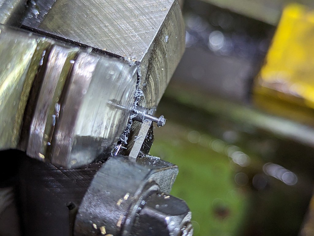 PXL_20230213_103154075 PXL_20230213_103154075 by Timothy Froud, on Flickr I drilled out the M1 holes in the skirt to 1mm and these were lightly formed over on the back with the rivet press to push the metal into a small chamfer. The back was then tidied up with the Dremel to make them flush. They were Blacked before riveting in place.  PXL_20230213_205002171 PXL_20230213_205002171 by Timothy Froud, on Flickr |
|
|
|
Post by Roger on Feb 13, 2023 22:04:33 GMT
I'd already drilled the shoulder pieces for the 0.5mm Brass rivets, but it was still fiddly to put it together, cut the rivets to length and rivet the backs over. It's so easy to mark the work or crush the rivets too much because it's all so soft. The shoulders will be painted Black, so there was the option to paint them first or after riveting. Obviously I opted for the second method, thinking that it would be next to impossible to rivet the painted items on and the rivets would need painting Black afterwards. I'll mask it all off and spray it on a 3D mount like all the other parts.  PXL_20230213_215435902 PXL_20230213_215435902 by Timothy Froud, on Flickr |
|
|
|
Post by Roger on Feb 14, 2023 10:58:36 GMT
I'll have to wait until the 1501 header plate is repainted before I can fit that, but the goal is to finish as many of the jobs as possible and get the parts I've made fitted permanently. The Shed Plate is held on with 0.8mm Steel Rivets, but they were too short to reach through the Smokebox Door. I decided to just countersink the holes enough to be able to rivet them over. 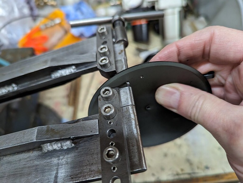 PXL_20230214_103509077 PXL_20230214_103509077 by Timothy Froud, on Flickr  PXL_20230214_103522744 PXL_20230214_103522744 by Timothy Froud, on Flickr  PXL_20230214_104034573 PXL_20230214_104034573 by Timothy Froud, on Flickr |
|
|
|
Post by ron61630 on Feb 15, 2023 11:59:42 GMT
Roger
Do you use any optical magnifiers when doing such small work?
Ron
|
|
|
|
Post by Roger on Feb 15, 2023 12:34:47 GMT
Roger Do you use any optical magnifiers when doing such small work? Ron Hi Ron, Generally not, but if it's really hard to see, I've recently bought a pair of X3 magnification Clip On lenses that go over my Varifocals and that helps. I tried those along with the 'Cheater Lens' when Tig Welding and that's a big help. I've also bought a high magnification Watch Makers type of Spectacles, but you can only really use one eye at a time with those. I might see if I can buy some Clip On lenses with a higher magnification. Having Varifocal lenses for the main glasses means I can focus one way or another by moving my head. |
|


