|
|
Post by Roger on Dec 29, 2014 23:10:40 GMT
I look forward to seeing that in action at the show then!
|
|
|
|
Post by Cro on Jan 4, 2015 16:55:25 GMT
So I am now back at uni which sadly means workshop time for this Christmas break is over but this doesn't mean the development of the valve won't continue whilst I am here! So as the valve stands it its attached to the test manifold I created which allows both the steam brake and ejector to be controlled independently with valves, it has a pressure gauge on the output of the steam brake to monitor the output pressure and also a vacuum gauge to monitor the vacuum being drawn via the ejector whilst allowing me to connect the whole block up to a driving truck of a friend in the clubs who has a vacuum cylinder controlling the brakes on one bogie and an air brake cylinder (hidden inside a vac cylinder) controlling the brake on the other bogie. The two photos below show the test manifold, ejector, valve and so on...   So After some initial testing of the steam brake I was pretty pleased to say that despite having very small passageways it does let enough through to activate a brake cylinder, between the input pressure and pressure measured on the output gauge you see a pressure drop of around 10psi, 15psi Max. Video below just shows the steam brake in action with input pressure set at 55psi.  The next step was to test the vacuum valve and make sure it is dropping the required vacuum fully but also to make sure it is not dropping it so suddenly and try and achieve some graduation with it. The vacuum brake disc itself has 96 holes at 0.4mm dia each, I had a lot of people say it wont work and there won't be enough air flow through them to drop the vacuum fully but all I can say is it worked fine and if anything lets it in a little too quick, this is partially down to the aligning holes on the sealing face but that is something I am now going to experiment with on the next batch of castings. Here is the video for the vacuum valve.  Now the keen eye'd ones of you will notice the valve not working 100% correctly in that video. You will notice that the steam brake is opening and closing whilst there is a vacuum, whilst it shows that the vacuum is drawing the valve closed as it should do what it is also showing is when the steam brake supply valve is opened the pressure behind the valve rod is too great for the vacuum to hold it closed.....problem? I think so!!! So I spent a bit of time crunching some numbers and decided that I needed to increase the size of the vacuum cylinder to overcome the pressure behind the steam brake valve rod, I went as large as I could fit in the body enlarging the piston from 0.230" to 0.275" and nervously adapted the casting to take a new cylinder by parting off the old and silver soldering on the new block shown in the next photo.  The new piston  After finishing off this I set it all back up (but forgot to video it this time). With mixed success it is improved, the vacuum holds the steam brake closed but when the vacuum is dropped and created again it does not fully close the steam brake without a little bit of help. This is more down to the friction created on the steam brake rod and I have now decided to re-design this to incorporate O-rings into different sections to allow for a better seal and adjust the porting slightly, these o-rings will be from watches as I need them small enough to suit the 3/32 bore so they are on order. I am confident now I can get the whole thing to work as expected and a little more time developing it and making maybe a few more I will get there with it. (there is a video of us testing it on the driving truck which isn't brilliant but sort of shows what I have mentioned above, if people want to see if let me know, its not great - you have been warned) I am going to have this on display at Ally Pally as our 5" Big Boy is now unable to make it to the show (bit complicated, don't ask) so we are re-arranging what we are taking and this will be there and hopefully with a compressor and the driving truck if people want to see it (kind of) work. Cheers, Adam |
|
|
|
Post by ejparrott on Jan 5, 2015 23:43:21 GMT
You could always market the drawings and castings, and offer machined parts for extra
|
|
|
|
Post by Cro on Jan 6, 2015 0:59:00 GMT
Once I am happy with how it works and the reliability of it then I would be more than happy to do that. I spent some time this evening working on all the cad models in preparation for another set of castings and any small changes I made when I was making this first one.
|
|
|
|
Post by runner42 on Jan 6, 2015 1:56:00 GMT
Would you consider an Everlasting Blowdown valve for a 3.5" gauge locomotive?
Brian |
|
|
|
Post by Cro on Jan 27, 2015 11:18:36 GMT
So haven't had any updates on this for a while as now back at uni and other projects have come my way. Since the last post I had the valve and test block on show at Ally Pally and was great to see some people there and get some great reactions from people, the most common comment was "wow, its so much smaller than I thought it was going to be from the pictures". I have finished making changes to a few of the design and it is now off with at the printers waiting to be checked over to see if a few extra parts can be printed and cast to save on time I have also spent time modelling the 7 1/4" version which is also now at the printers being checked, I am hoping to add a little more detail into this one and also have the passageways cast internally like the real thing which also helps with the design and manufacture of certain bits. Problem is I won't have time till Easter at the earliest if not later than that with my finals coming up in April to touch any castings that come in, I am hoping someone will help me out with the first castings that come in for the 7 1/4" version so that I can get it mocked up and tested for people too see. (If anyone is really keen to machine it up for me drop me an email, should be a lot less in this one as most is cast) Here is a quick shot from the CAD models showing the increase in size between the 5" and 7 1/4" models and the extra little details it has.  I am now accumulating drawings for a lot more fittings for BR locos and some Stanier items so when time allows I am cracking on with these as well as a few castings for mine and Ben's V2's. Adam |
|
|
|
Post by Deleted on Jan 27, 2015 13:42:42 GMT
Hi Adam
I'm very impressed with your work..love the attention to detail on these castings....I'm not sure which parts you are doing for Ben or if they are suitable for my Gresley A1 but if they are I may well be interested in obtaining the relevant castings from you if that's possible.....I'm sure Ben will know what's suitable and what isn't.
keep up the good work..
Pete
|
|
|
|
Post by Cro on Jan 27, 2015 13:47:27 GMT
Pete,
Thanks, I have got drawn into the detail front after working on the 9f and seeing what other people like Mike have done with this process.
For Ben so far I am just doing the chimney to suit his copper cap and to better the C*** casting he had before so he'll have two options and also doing the petticoat pipe with ejector ring to match.
Adam
|
|
|
|
Post by Deleted on Jan 27, 2015 13:52:00 GMT
Pete, Thanks, I have got drawn into the detail front after working on the 9f and seeing what other people like Mike have done with this process. For Ben so far I am just doing the chimney to suit his copper cap and to better the C*** casting he had before so he'll have two options and also doing the petticoat pipe with ejector ring to match. Adam ahh...ok Adam..don't think those will fit mine and I was thinking more of backhead fittings......  thanks anyway... Pete |
|
|
|
Post by Cro on Jan 27, 2015 14:10:40 GMT
Pete, Thanks, I have got drawn into the detail front after working on the 9f and seeing what other people like Mike have done with this process. For Ben so far I am just doing the chimney to suit his copper cap and to better the C*** casting he had before so he'll have two options and also doing the petticoat pipe with ejector ring to match. Adam ahh...ok Adam..don't think those will fit mine and I was thinking more of backhead fittings...... thanks anyway... Pete Those will be coming later on but not quite ready for them just yet! Got a ton of BR ones to do first |
|
|
|
Post by Deleted on Jan 29, 2015 1:03:51 GMT
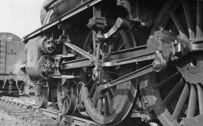
Pete, I'm 99% sure the chimney is the same on A1 and V2, going on 2 things, the first being the almost identical dimensions between Dons and Michaels drawings for the 2 chimneys and the fact that the same casting is used for both Michaels V2 and FS. On top of that Adam is working his magic on making a petticoat with cast in exhaust ring as per prototype This one is the same thing but off 34059  The inside has many many holes drilled at an angle as close to vertical as the petticoat will allow into the ring so the vacuum exhaust exits up the inside of the petticoat. Keep up the great work Adam! Cheers Ben |
|
|
|
Post by Deleted on Jan 29, 2015 8:03:00 GMT
hi Ben if the petticoats are the same for the A1's and V2's then I may well be interested in this. Don's drawing in very similar to your photo, stating 12 No.51 holes to be drilled angled up around the circumference behind the ring, not an easy thing to do when fabricating but I wonder is this possible with a 3D printed item, yes the item complete can be 3D printed but can it be cast with the holes as I can't see how you could drill these when in one piece. Not saying it's impossible but suspect this could be very problematic??  Pete |
|
44767
Statesman

Posts: 529
|
Post by 44767 on Jan 29, 2015 8:07:56 GMT
It could be printed but you'd never get the support wax out from inside the ring. I'd suggest it could be done by having the bottom flange of the ring as (two) separate pieces and silver solder them on afterwards. Or, as you can see in the picture of full size one, it could be lost wax cast in two pieces, split where you can see it for getting the core into the mould, and then the two pieces soldered together.
|
|
|
|
Post by ejparrott on Jan 29, 2015 9:11:59 GMT
Doug Hewson did it with the Std 4, I'd have to get the drawings out to check but I'm pretty sure he left part of the ring off and silver soldered it back on after...I think it was the bottom face
|
|
44767
Statesman
Posts: 529
|
Post by 44767 on Jan 29, 2015 9:18:27 GMT
Yes, that's how he did it. You can then get the hole at quite an angle and afterwards cap the bottom. Actually, just thinking about it, he may have made a ring to cap the OD of the chamber. Otherwise the end cap would have to be in two pieces as the petticoat end in larger than the ring.
|
|
|
|
Post by ejparrott on Jan 29, 2015 11:27:32 GMT
I'll have to dig it out and have a look sometime..haven't time today..just spent 2 hours getting a tyre inspected to find it's got a tiny hole in the sidewall...another £110 down...  |
|
|
|
Post by Cro on Jan 29, 2015 11:56:27 GMT
Mike,
That was my one worry and haven't had a time to go back and have a think about it properly, I would have either left the outer ring off or the top ring as these would be the easiest to make/fit. What I wasn't sure about was would the holes on the inside of the petticoat for the ejector have a crisp enough edge or would they need a finishing drill.
I have done the chimney from m full size GA but Ben's is slightly different as he wants the base to take the copper cap. How similar is the A1 chimney to the V2?
|
|
uuu
Elder Statesman
 your message here...
Posts: 2,812
|
Post by uuu on Jan 29, 2015 17:33:28 GMT
Station Road Steam have a part-built 7 1/4 King with this: .jpg) .jpg) Wilf |
|
|
|
Post by Deleted on Jan 30, 2015 15:15:02 GMT
I don't know the ins and outs of casting in great detail but the one in the pic I posted had 2" holes around the ring which when finished were tapped and had washout plugs fitted which were then ground flush (this can just be seen in the pic).
Mike, could this not be done in miniature as the way of getting the wax out?
Cheers
Ben
|
|
jma1009
Elder Statesman
Posts: 5,901
|
Post by jma1009 on Jan 30, 2015 17:33:06 GMT
hi adam and ben,
i had a beautifully made petticoat pipe of the combined blower ring type for a 3.5"g LMS Duchess, but i doubt very much if it would have been effective, and would also have mucked up the draughting if at anytime the blower was turned on whilst the loco was moving under steam. the laurie lawrence 4 jet blower fitting to go round the blastpipe nozzle cant be beaten for effectiveness and simplicity IMHO.
cheers,
julian
|
|