|
|
Post by terrier060 on Jan 25, 2019 11:30:47 GMT
Never thought of using the Tormach Roger - I was going to use a bit of old file and shape it by hand as Chaddock described in his cutter grinder book which I made many years ago. But as I already have the drawing and some gauge plate I may do it your way.
|
|
|
|
Post by Roger on Jan 25, 2019 12:31:51 GMT
Never thought of using the Tormach Roger - I was going to use a bit of old file and shape it by hand as Chaddock described in his cutter grinder book which I made many years ago. But as I already have the drawing and some gauge plate I may do it your way. Just take the cutting slowly, using say half the feeds you're currently using and it will machine easily enough. |
|
|
|
Post by David on Jan 26, 2019 8:44:11 GMT
NYCCNC has a video on making a form cutter using a Tormach. But theirs was for plastic so may not have been tool steel.
|
|
|
|
Post by Roger on Jan 26, 2019 9:35:13 GMT
NYCCNC has a video on making a form cutter using a Tormach. But theirs was for plastic so may not have been tool steel. This trick is to define a model in such a way that the desired profile is defined on a plane tilted up at the front clearance angle. That profile is then projected down to create the modified profile in the X/Y plane so you can machine the part while it's tilted. It's simple enough. Once you've created the tool shape, you need to be able to machine just the front, and this video appears to show you how to do that. I have two models that I keep, one for each size of Gauge Plate that I keep for this purpose. I just open the model, modify the profile and then save it. Obviously each profile may require very different tool diameters determined by the sharpest internal corner required. |
|
|
|
Post by nick952 on Jan 26, 2019 14:34:23 GMT
I gave up "Tilting" the gauge plate blank ages ago, once I found these cutters:- www.aliexpress.com/item/R0-25-0-5-0-75-1-0mm-with-3-175mm-1-8-shank-Tungsten-solid/32801099417.html?spm=2114.search0104.3.15.23534dd0tvKKKa&ws_ab_test=searchweb0_0,searchweb201602_5_10065_10068_10130_10547_319_317_10548_10696_10192_10190_453_10084_454_10083_433_10618_431_10307_10820_10301_10821_10303_537_536_10902_10059_10884_10887_100031_321_322_10103,searchweb201603_54,ppcSwitch_0&algo_expid=acc03ddf-c9a5-407d-8408-f2d8cba4377d-2&algo_pvid=acc03ddf-c9a5-407d-8408-f2d8cba4377d&transAbTest=ae803_5 The hardest part is initially setting the Z offset required to define the correct form size, but once done this is stored for future forms. Using the tapered cutter provides the front clearance angle and side clearance angle around all the form, but don't forget that you need to Invert the form, as you will be cutting the form tool upside down. |
|
|
|
Post by terrier060 on Jan 27, 2019 23:28:29 GMT
Thanks Dave, Roger, Nick - I will give that a go. Today I did two of the rear sides and I slowed the rpm to 2250 and the feed to 0.7 in/min with 12thou depth of cut. This seems to be OK but I wish I could find out what the tool was I originally used. I think is must have been the K2 coated one, but they are about £7.50 each. 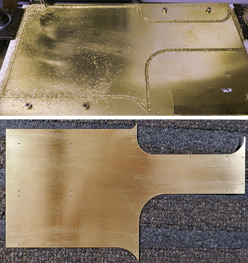 Cab side rear Cab side rear by ed cloutman, on Flickr |
|
|
|
Post by David on Jan 28, 2019 1:37:02 GMT
Great result Ed. Translating into colour that was 0.3mm doc and 18mm/min.
Looking forward to seeing the glue experiment.
|
|
|
|
Post by terrier060 on Jan 30, 2019 13:26:41 GMT
Hi David - yes just about to order the adhesive, although I have emailed Ion at Permabond to make sure that it goes off hard enough to sand and that paint will adhere to it.
I also found I have some thick-walled bronze bearing material which is just the right size for the bezels, but the colour is a bit bronzy as one would expect so don't know whether to use it or not. Does save a lot of machining and waste though.
|
|
|
|
Post by Jim Scott on Jan 30, 2019 16:13:28 GMT
I also found I have some thick-walled bronze bearing material which is just the right size for the bezels, but the colour is a bit bronzy as one would expect so don't know whether to use it or not. Does save a lot of machining and waste though. Hi Ed, Have you considered machining these from sheet on your mill? The cab side is mainly flat with a small recess for the glass, - this could be put in whilst milling out the 'bore'. Turning over the sheet would allow you to finish the front profile Jim S |
|
|
|
Post by terrier060 on Jan 30, 2019 19:49:36 GMT
Funny you should say that Jim - yes I did consider it, but not until after I had bought the brass bar so it was too late. It does seem so wasteful to buy 2.5" bar and then machine most of the centre away. That is why I am tempted to use the hollow bronze tube and except that the colour will be a bit redder than brass. Also I am not as patient as Roger and it would take an awfully long time to machine 16 of these on the Tormach compared to the lathe.
|
|
|
|
Post by David on Jan 31, 2019 0:55:08 GMT
Ed, this sounds like what I've just been through with the 'porthole' window rims for my mogul. You'll only bore in a little way and everything will be concentric. I wasted 6 hours making them from plate and then used the brass bar anyway. I strongly recommend the lathe!
I can't imagine turning whatever profile is required would tax your skills but if still want to use the mill you can just stick the bar in a 3-jaw bolted to the mill table as Roger often does and part off in the lathe.
|
|
|
|
Post by terrier060 on Jan 31, 2019 21:29:58 GMT
You can see my dilemma David - I have the perfect material here with a minimum amount of machining, but being leaded-bronze there is a slight pinkish tinge to it. I will take another picture outdoors tomorrow if the snow keeps of - it will show the difference in colour better. Once they oxidise after a period of months the colour gets similar in any case. 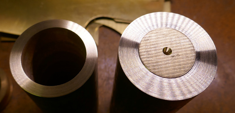 Bezel material Bezel material by ed cloutman, on Flickr |
|
|
|
Post by steamer5 on Feb 1, 2019 8:50:23 GMT
Hi Ed,
A couple of thoughts....bear in mind I haven't done either YET!!
On the lathe trepan into the end of the bar the ID of the window deep enough for the number required.....maybe just over that required for 1 at a time. Profile the end as required for the hole, part off to thickness required, bar now has a step with useable material...I guess the frames are only 3 to 5 mm thick & depending on your parting off blade maybe 8mm per window.
On your mill, stand on end plunge with end mill to trepan end, profile rim to suit, part off using a slitting saw repeat. With your skill on the Tormach should be no problem!
Still enjoying your journey, picking up great ideas!
Cheers Kerrin
|
|
|
|
Post by Roger on Feb 1, 2019 8:58:37 GMT
Personally, I don't see the cost of a short piece of solid Brass as much of an expense compared to what we all spend on everything else.
I would make a form tool which can be plunged in until it just cleans up the turned maximum diameter. Then I'd bore out enough for all of the windows, but make that bore say 2mm under the finished size. The I'd use the parting tool to go in just below the finished inside diameter and stop. To finish the part, I'd then bore it to size. That way I think you have the best chance of separating the finished part from the stock without damaging it. Parting it off conventionally might be tricky.
|
|
|
|
Post by terrier060 on Feb 1, 2019 13:04:35 GMT
OK I think I will adopt both your ideas. I shall use a form tool to do the outside of the bezels, to ensure they all look the same. Turn the outside and inside diameter to size. Reverse in the chuck in a holding piece and turn the groove for the glass and face to thickness. Make a simple jig to hold them on the Tormach and using the centre as reference, drill eight of the bezels 8 x No.55 12BA clearance and drill 8 x No.61 tapping for the other eight bezels.
Still not sure whether to use the bronze or brass. After they have weathered the colours do look similar.
|
|
mbrown
Elder Statesman

Posts: 1,720
|
Post by mbrown on Feb 1, 2019 14:46:48 GMT
I am sure you will choose an appropriate method to suit your materials and equipment. But, just for the sake of suggesting various options, I made the spectacle rims for my Bagnall by trepanning them from 1/8" brass sheet. If I recall correctly, I sawed the outer edge roughly to shape, Loctited two pieces together, then chucked them in the outside jaws and trepanned the inside diameter. I then held them in the chuck by the inside diameter and turned the outside diameter. With two thicknesses together, I held them by the inside diameter to turn the fancy profile (very similar to the Stroudley rims) on one, reverse in the chuck, and turn the other. Doing them together makes it easy to make them identical.
So if anyone has sheet but no suitable bar, it can still be done.
Malcolm
|
|
|
|
Post by terrier060 on Feb 3, 2019 0:38:57 GMT
Virtually all the pieces have been cut out now for the loco cabs, except for the roofs. I am experimenting with the window bezels, just to give me an idea of overall size. The ring directly in front of the parting off is only 1/32nd wide and it still looks too thick. If I go much thinner there will be no thread to take the screws, so I will have to round the corner which should make it look a bit thinner. I have to make the form tool to contour the inner part. The OD and ID are to finished size, so that I can get a better idea of the finished result. 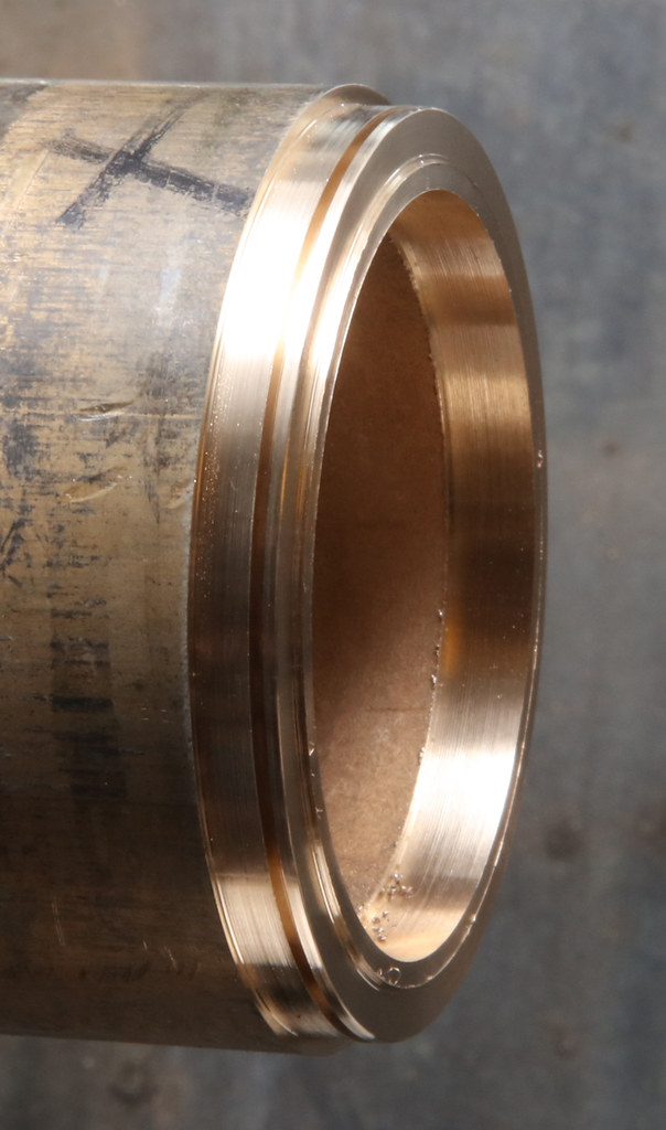 Bezel 01 Bezel 01 by ed cloutman, on Flickr |
|
|
|
Post by terrier060 on Feb 3, 2019 11:50:40 GMT
Here is the cab flat-pack for the two cabs - I could not resist putting the number plate on, and yes, thanks to CNC the 12BA holes lined up perfectly - much impressed with the Tormach. 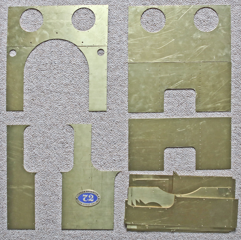 Cab flat pack Cab flat pack by ed cloutman, on Flickr |
|
mbrown
Elder Statesman
Posts: 1,720
|
Post by mbrown on Feb 3, 2019 13:08:49 GMT
I hope you write better assembly instructions than Ikea!
Malcolm
|
|
|
|
Post by terrier060 on Feb 8, 2019 13:45:11 GMT
Had a few days off writing a paper with a colleague of mine - long overdue! Am now bezelled-out! I am now going to make a jig to centre them on the Tormach and spot the holes. Not only is this quicker than trying to do them on a rotary table, but they should exactly match the holes in the spectacle plate. They are not very thick - 40 thou on average on the flat part so there is not a lot of thread. I will try one and see how it fits and if it seems dodgy then I will glue the outside bezel and thread the spectacle plate as well as the outer bezel. The coal door sliders were machined on the Tormach. There is a 14 thou shim under the runner so that the door runs smoothly without touching the back of the cab. The little hole at the top serves two purposes. On the full-size loco it holds the door in the up position via a spring-loaded pin. On the model it also holds on the base of the rear spectacle plate and rear half of the roof. The roof will slot into the top and bottom strap which stiffens the roof and stops droning. 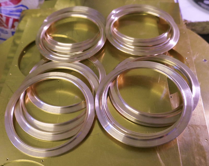 Cab bezels Cab bezels by ed cloutman, on Flickr 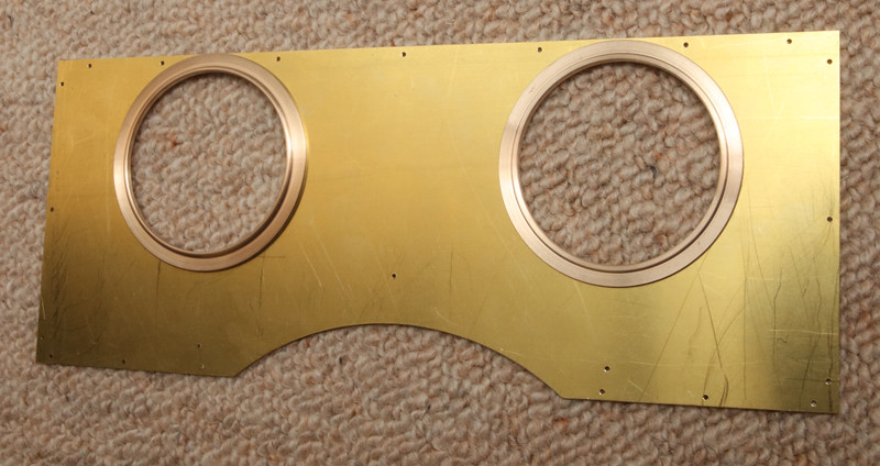 Bezels 01 Bezels 01 by ed cloutman, on Flickr 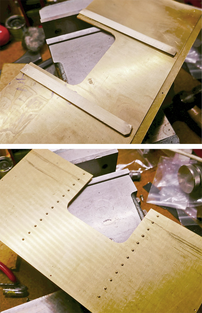 Coal Bunker Door Runners Coal Bunker Door Runners by ed cloutman, on Flickr |
|


