|
|
Post by terrier060 on Jan 16, 2018 21:18:08 GMT
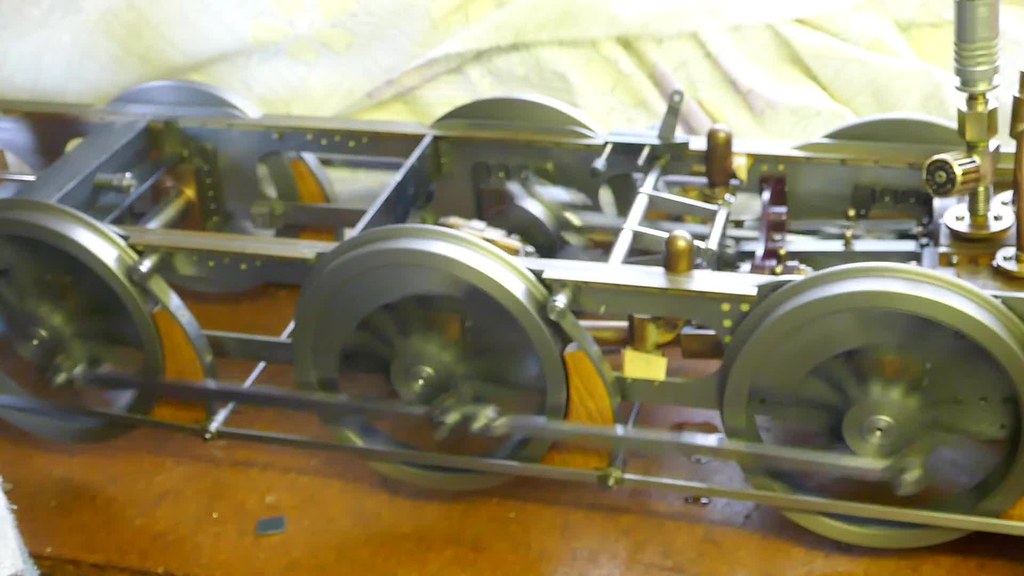
Today as been a long and hard day. I hate bending thin-walled copper tube! I found some of that low-melting point white metal stuff and used that for the sharp bends, but they are far from perfect. However the pipework leaves the flues nice and clear for sweeping and draught. Now comes the really tricky bit, and I will have Justine's eagle eye watching! Cut the hole for the chimney and fit the choke - then bend up and align the blast-pipe. Not looking forward to that. 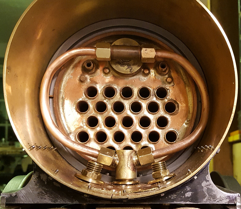 Steam inlet pipes Steam inlet pipes by Ed Cloutman, on Flickr I forgot to add that I drew the pipwork in AutoCAD and was able to get the length of Cu pipe required (6 3/16"). So I was able to true the ends of the tubes in the lathe before I started bending them. The length worked out perfectly so I was quite pleased. 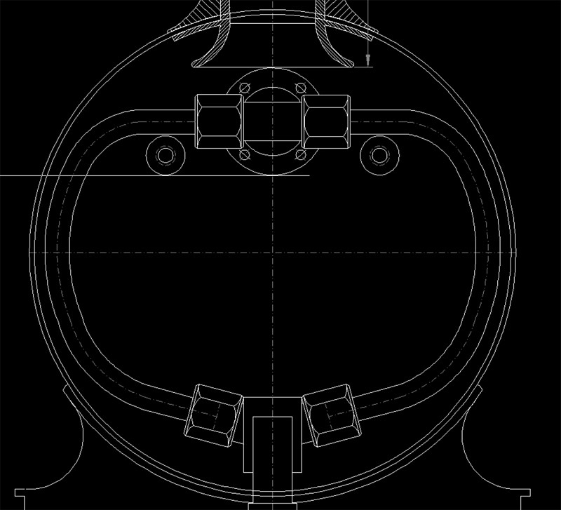 Pipework steam inlet Pipework steam inlet by Ed Cloutman, on Flickr |
|
|
|
Post by Roger on Jan 16, 2018 21:31:30 GMT
Hi Ed,
That's worked out well then, and there's nothing in the path of the gasses either.
I'm curious to know why you don't have any Superheaters? Obviously it simplifies the pipework no end, but I would have thought they would be beneficial?
I presume the snifting valve is somehow incorporated in the pipework below the smokebox?
|
|
|
|
Post by terrier060 on Jan 16, 2018 21:44:23 GMT
Hi Roger
Yes I forgot about the snifting valve! But there are several places I can fit one.
I don't want this thread to become complicated with the pros and cons of superheaters, because I know this is a contentious issue, but to my knowledge no research has been done on models and I felt that the extra flue area was more beneficial than superheater elements which from experience soon get blocked up. Also if you look at full size, the elements travel back and forth four times through thirty or more tubes. The surface heating area is far in excess of anything achievable on a model. As a friend of mine once said - it probably dries the steam a bit and not much more.
Anyway, Fenchurch has managed for 145 years without them!
|
|
|
|
Post by Roger on Jan 16, 2018 22:26:48 GMT
Hi Roger Yes I forgot about the snifting valve! But there are several places I can fit one. I don't want this thread to become complicated with the pros and cons of superheaters, because I know this is a contentious issue, but to my knowledge no research has been done on models and I felt that the extra flue area was more beneficial than superheater elements which from experience soon get blocked up. Also if you look at full size, the elements travel back and forth four times through thirty or more tubes. The surface heating area is far in excess of anything achievable on a model. As a friend of mine once said - it probably dries the steam a bit and not much more. Anyway, Fenchurch has managed for 145 years without them! Hi Ed, Ah, I did wonder, but I don't know the design, so I thought there might be a cunning arrangement I couldn't see. Fair enough about the Superheaters, 1501 doesn't have any either. I won't add any more to that, someone can start another thread if they want to explore the pros and cons of them, a most interesting subject. |
|
|
|
Post by terrier060 on Jan 17, 2018 10:06:11 GMT
Hi Roger Julian and I have a more serious problem. The position of the chimney in the A1X version of 'Fenchurch'. Photos point towards it being central on the longer smokebox, but some images show it slightly rear of central. I am hesitant about drilling a 'loody great hole in the top until I am sure of its position. If anyone is going near the smokebox at the Bluebell (or works there), which may be lying outside somewhere or even scrapped by now - I should be very please to have measurements. Images below taken from the Blubell Railway and Villa team to whom I am very grateful. 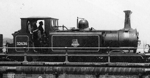 Fenchurch Sheet 006 detail Fenchurch Sheet 006 detail by Ed Cloutman, on Flickr 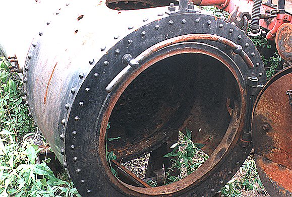 985_027 985_027 by Ed Cloutman, on Flickr 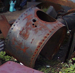 smokebox007za001 smokebox007za001 by Ed Cloutman, on Flickr |
|
|
|
Post by terrier060 on Jan 19, 2018 9:39:36 GMT
Bit of a delay - workshop got flooded! Should never have put it under the bathrooms!
|
|
|
|
Post by simplyloco on Jan 19, 2018 9:43:20 GMT
Bit of a delay - workshop got flooded! Should never have put it under the bathrooms! At least you've got all your tools on tap!  |
|
|
|
Post by terrier060 on Jan 24, 2018 11:54:31 GMT
Very droll!
|
|
|
|
Post by terrier060 on Jan 29, 2018 12:57:04 GMT
|
|
|
|
Post by terrier060 on Jan 29, 2018 15:46:43 GMT
I have been wondering whether anyone would be interested in this little program I wrote to scale their models. Basically you enter the full-size scale - in my case the four feet eight and a half inches rail gauge, then the model gauge seven and a quarter inches. You can then enter the imperial measurements from full-size drawings and get the results in imperial or decimal. It allows decimal input as well. One can scale up or down. It also gives you a range if you don't like working to 64ths. I had to do something to make life easier when scaling the 'Terrier' drawings. My loco will be slightly larger than the usual 7.25" scale used by ME designers. 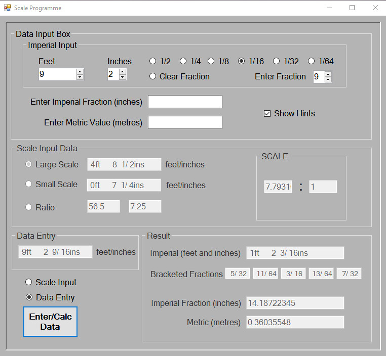 Scale Program Scale Program by Ed Cloutman, on Flickr |
|
|
|
Post by cjfield93 on Jan 31, 2018 21:39:33 GMT
I for one would be interested in your scaling/ conversion program. Having no real drawings to work from for my particular project and not being the most fluent in maths this would make life so much easier. Like most we've all got pipe dreams to model locos or items of rolling stock where the drawings aren't available commercially and scaling them down can be a real challenge. I'm guessing your program would work perfectly fine with 5" gauge?
Chris
|
|
|
|
Post by terrier060 on Feb 1, 2018 17:45:26 GMT
Hi Chris
Anyone is welcome to have a copy of this program. I am not sure of the best way to send it - probably by personal email. If you would like to PM me with your details.
Although the part of the program I use works fine and I have checked it as far as I can there may be glitches I have not found, so as long as you accept this. In fact programs usually need to be used by different people for bugs to be highlighted. I am quite happy to sort them out if any are found. Hopefully non will be.
I did once write a guide to how it works, but it may be easier to just do it over the phone (if you are in the UK). If not I will write a simple guide. It is pretty easy to use in any case.
It is written in Visual Basic
Ed
|
|
|
|
Post by 92220 on Feb 1, 2018 18:24:40 GMT
I for one would be interested in your scaling/ conversion program. Having no real drawings to work from for my particular project and not being the most fluent in maths this would make life so much easier. Like most we've all got pipe dreams to model locos or items of rolling stock where the drawings aren't available commercially and scaling them down can be a real challenge. I'm guessing your program would work perfectly fine with 5" gauge? Chris Hi Chris.
You could always do what I do, which is easy, 'cos I work in imperial....multiply the fullsize dimension by 0.0885 and you have the exact scale dimension for 5" gauge. i.e. 5" divided by 56.5" (4' 8.1/2"). i.e. 56.5" x 0.0885 = 5.00025" which I think is near enough to call 'exact'. If you want it in metric, just multiply again x 25.4.
Ed's program would be very handy for those who prefer to work in imperial fractions though, like the older commercial drawings.
Bob.
|
|
|
|
Post by terrier060 on Feb 2, 2018 18:20:58 GMT
A few people have expressed an interest in the scale program so here is a short description on how it works.
Scale Program
My main reason for writing this little program was to quickly convert full size drawings and measurements I had taken of the full size locomotive, when I was designing my 7.25 inch gauge 'Terriers'.
As I work in imperial and all my machines are in imperial, I needed a quick way of entering the fractional data.
I wanted the output to be fractional as well, to the nearest 1/64th. For measurements that did not need to be to the nearest 1/64th I also wanted the option of bracketing to the next nearest value, hence the range shown in the Results panel.
It seemed silly not to have a metric conversion for those who now work in metric, so that is provided also.
It also gives the results to thousandths of an inch for dimensions for cylinders etc where higher accuracy is required.
Method
Use the data input box to enter the imperial values. You can type these in or use the spin arrows. To input fractions, click on the relevant radio button and use the 'Enter Fraction' box to insert the numerator.
1. Start by entering the large scale or gauge - in my case four feet eight and a half inches. Press the Enter/Calc button and you will see the result in the 'Large Scale' box.
2. Click on the 'Small Scale' radio button and enter the small scale or gauge as in 1 above (in my case 7.25 inches). This will give a ratio of 7.7931 to 1, or one and nine sixteenths of an inch to the foot, rather than the more normally used one and a half inches to the foot - thus your locomotive will be slightly larger than if you used the most common ratio.
3. The ratio value will appear in the 'Scale' box.
4. Click the 'Data Entry' radio button and start entering your full size dimensions in the 'Imperial Input' box, pressing The Enter/Calc button to get the result.
If you want to work to a different scale you can add your own scale ratio in 1 above by selecting the 'Ratio' radio button.
You can also work directly in Imperial fractions or metric using the boxes alongside the 'Show Hints' box.
You can work in any scale and scale up or down.
|
|
|
|
Post by terrier060 on Feb 3, 2018 9:45:15 GMT
Chris I never answered your question properly, I have just noticed. It certainly will scale to 5 inch gauge. If you want a slightly larger loco then you scale by rail gauges (4ft 8 1/2in large scale and 5in small scale). This gives a ratio of 11.3 to 1. If you want to scale as most ME designers do of 1in to the foot then you just put 12in in the large scale and 1in in the small scale - a 12 to 1 ratio.
Ed
|
|
Myford Matt
Statesman
 There are two ways to run a railway, the Great Western way, and the wrong way.
Posts: 621
|
Post by Myford Matt on Feb 3, 2018 18:48:48 GMT
Does anyone know why we didn't have a 7 1/16 gauge?
It would then simply be a nice and very-easy-to-use ratio of 1:8 compared to full scale.
|
|
|
|
Post by terrier060 on Feb 4, 2018 14:51:46 GMT
|
|
|
|
Post by terrier060 on Feb 6, 2018 15:49:38 GMT
Does anyone have details of the insides of the blower valve on the LHS of the 'Terrier' smokebox and what I think is the cylinder lubricator on the RHS? This may be one for Julian! Or maybe someone could put me in touch with someone who has had one of these apart.
Many thanks
Ed
|
|
|
|
Post by terrier060 on Feb 16, 2018 23:18:18 GMT
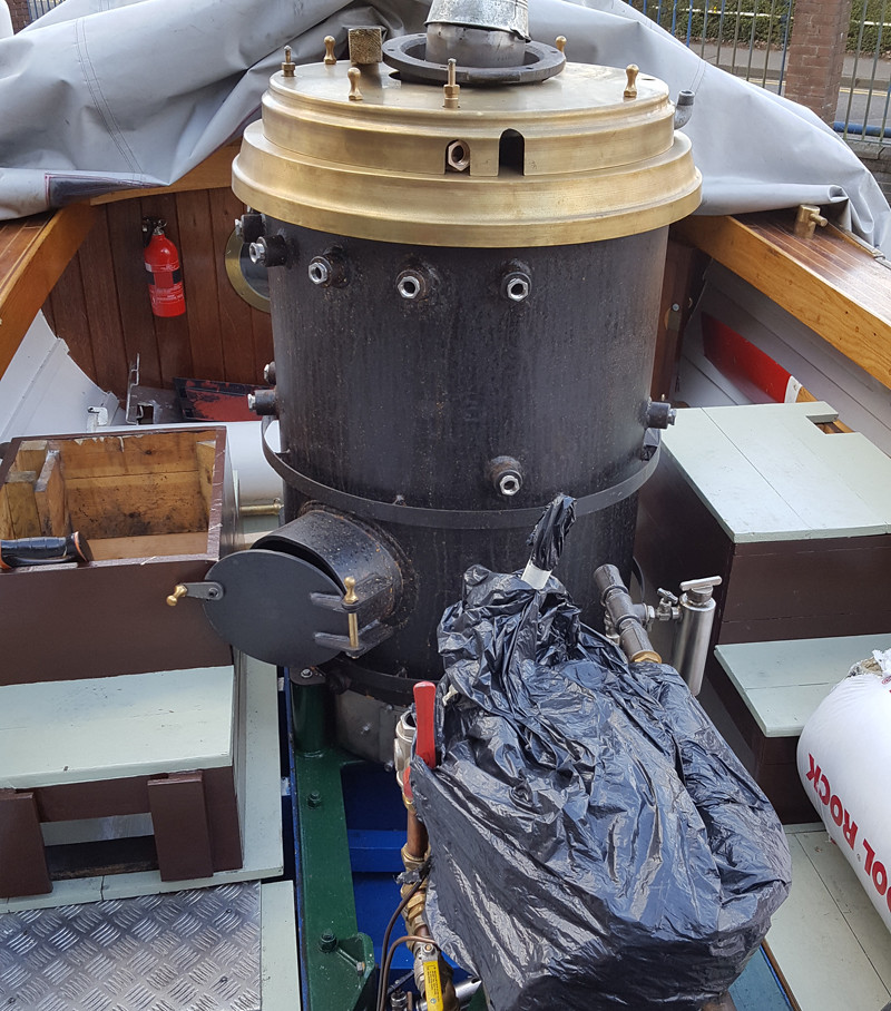
Been quiet for some time because I am doing the tedious job of 24 spring hangers (top) and 24 spring hangers (bottom) plus dummy leaf springs which means machining 15 metres of 1/16" mild steel to 3/64". The drawings are in one of my early posts. The dummies cover coil springs which I am using as I can get finer adjustment and softer springing which improves adhesion. Today I was helping my friend with his launch - we managed to bolt down the boiler after some headaches as the chap who made the boiler made the holes too small and well out of line. There are also problems with the water gauge glasses as the top and bottom fittings are out-of-line, so we hope that the clearances for the gauge glasses will cope. Very poor workmanship and very disappointed with the boiler-maker. We did manage to lag the boiler and am now working on the wooden lagging. For those reading 'piston rings' - my loco was superheated but well lubricated with a hydrostatic lubricator with sight feed and atomiser. The rings may have been viton - I can't remember, but the pistons are not split as far as I remember, the rings must have been rolled into the grooves. When I had a look at them after some years of running, they had flattened a little but were still sealing well. The other advantage was that the very small pipes on the drain cocks kept blocking up when I was using graphite yarn packing, which was the main reason I tried 'O' rings. You have heard the 'beat' on my 'Terriers'. Well again there is one main groove in the piston with one 'O' ring. The pistons are stainless running in gunmetal bores, and are shaped like the full-size (except for the 'O' rings)! 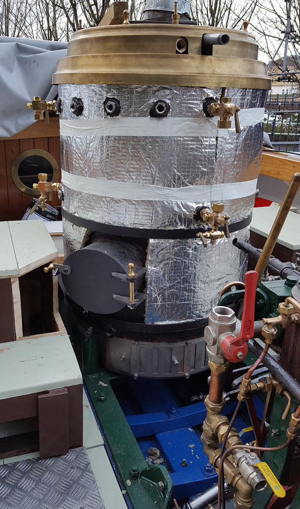 Boiler Lagging Boiler Lagging by Ed Cloutman, on Flickr |
|
|
|
Post by terrier060 on Feb 19, 2018 19:51:20 GMT
OK Roger - you asked for it! Not quite as picturesque as your images, but a lot of repetition! 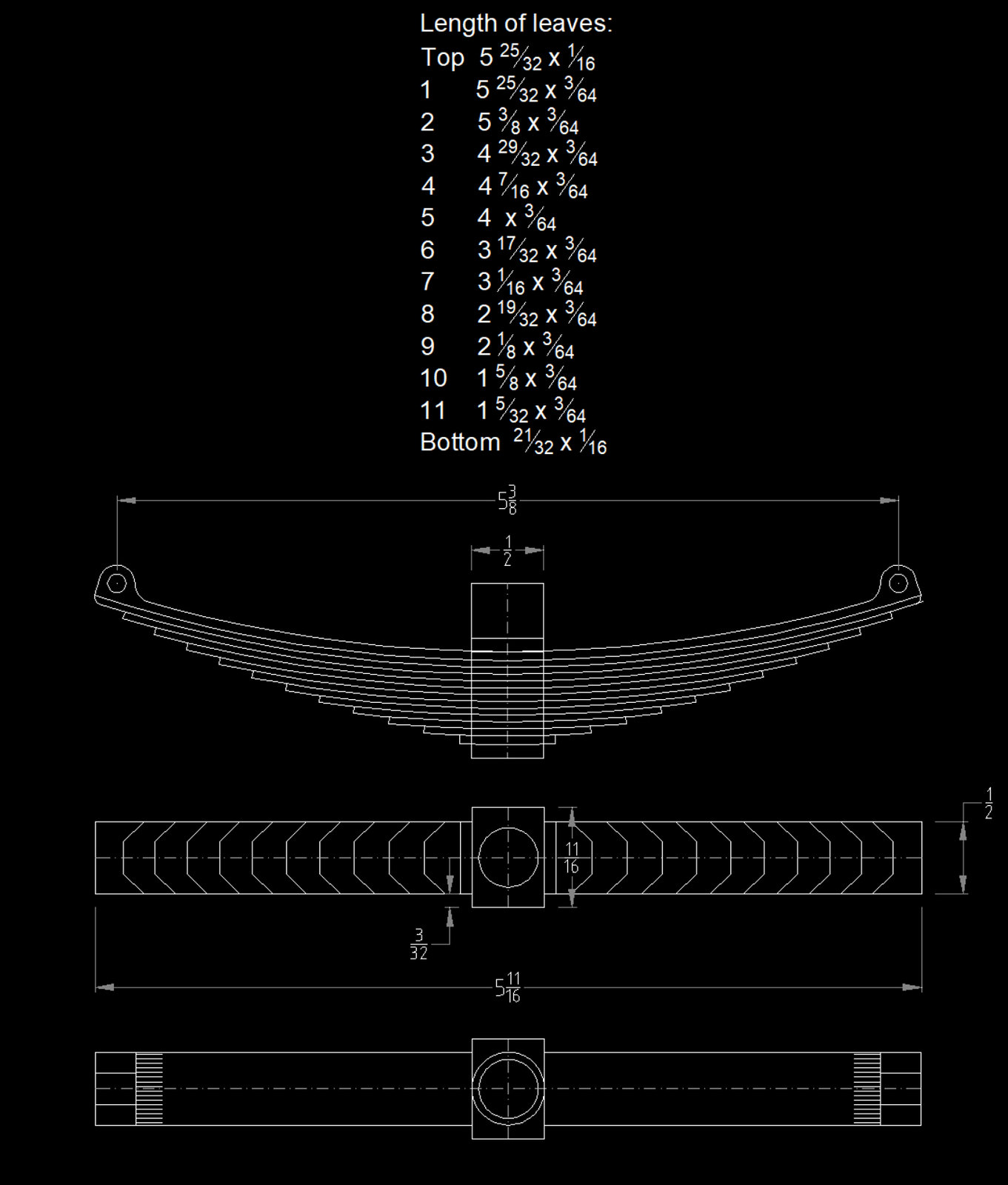 Spring DWG 01 Spring DWG 01 by Ed Cloutman, on Flickr 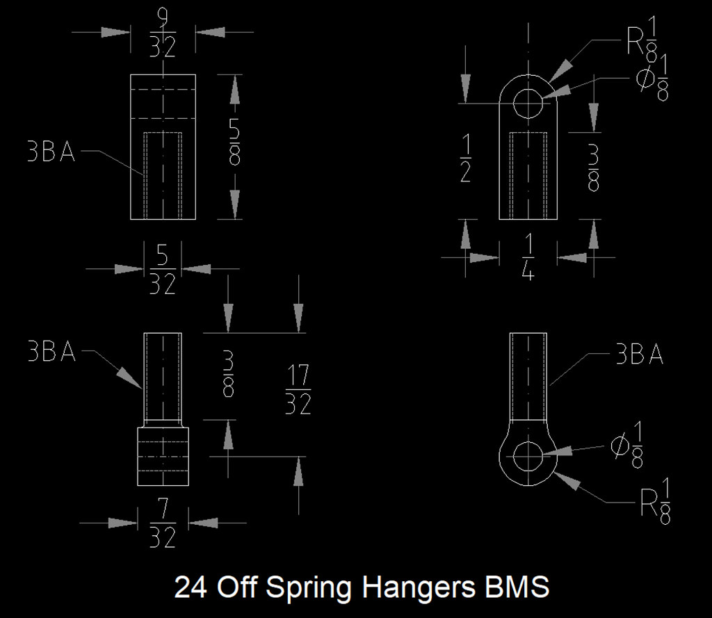 Spring Hanger DWG Spring Hanger DWG by Ed Cloutman, on Flickr 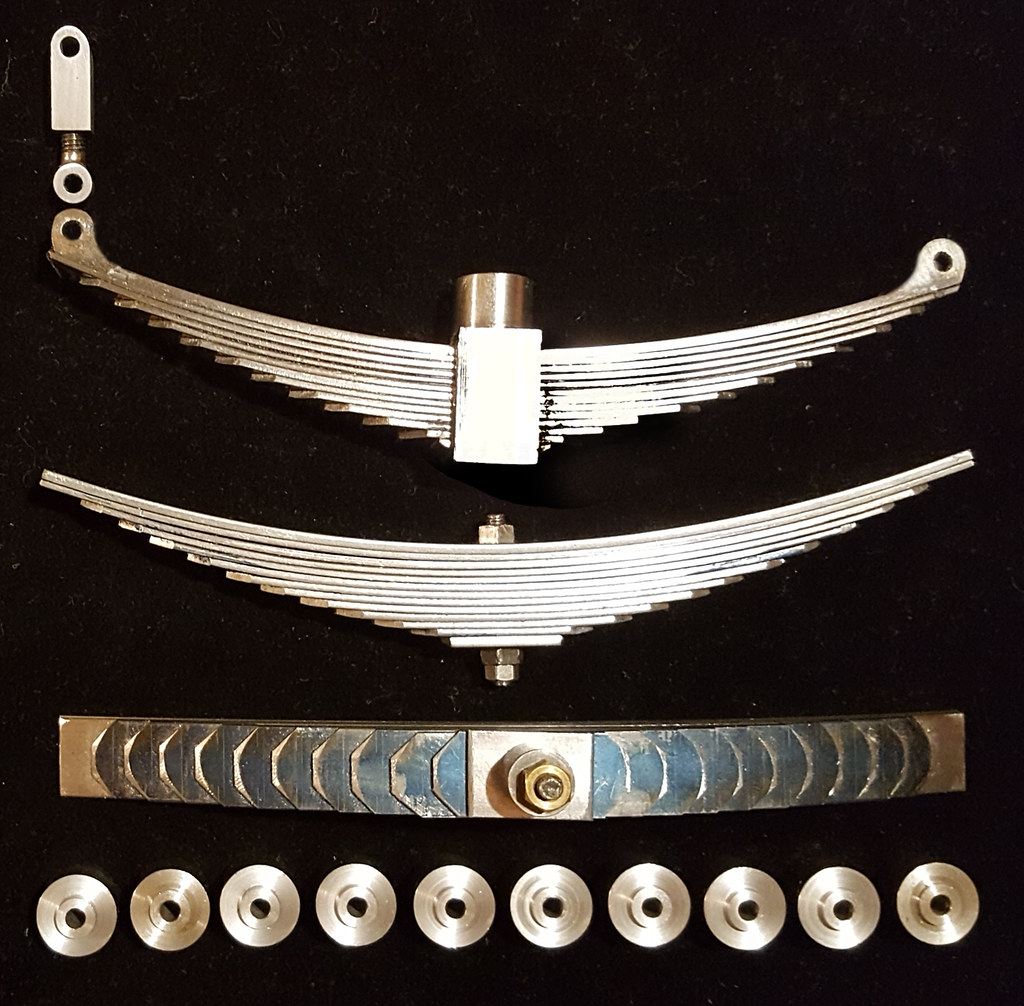 Springs 02 Springs 02 by Ed Cloutman, on Flickr The CAD drawings give the length of each spring leaf. These are then belt-sanded to form the wedge ends and all the springs and the central boss are held together with the central pin and silver-soldered. The central boss is then drilled to take the coil spring which is hidden from view inside. |
|