|
|
Post by GWR 101 on Aug 19, 2019 8:47:21 GMT
Roger, I am a strong believer that one of the most vital parts of any machine tool is the bit that is attached to the hand wheels or in modern times the keyboard. Regards Paul.  |
|
|
|
Post by Roger on Aug 19, 2019 9:41:30 GMT
 20180110_111016 20180110_111016 by Timothy Froud, on Flickr This is the hinge pin being made from 2mm diameter Stainless Steel rod. The final pin diameter is 1.4mm which is not a standard size, and it's also very thin to be able to cross drill unsupported. This way it's easier to cross drill as it's not as flexible. The drill is 0.6mm diameter.  20190819_093856 20190819_093856 by Timothy Froud, on Flickr The diameter was reduced on the Jones & Shipman Tool & Cutter Grinder.  20190819_100218 20190819_100218 by Timothy Froud, on Flickr The split pins are the smallest ones I make.  20190819_102720 20190819_102720 by Timothy Froud, on Flickr |
|
baldric
E-xcellent poster

Posts: 208
|
Post by baldric on Aug 19, 2019 11:30:23 GMT
If it all relied on batteries in that box, how were they recharged, and what happened if the loco went out with flat batteries? I assume they were swapped/charged on shed, there is no way of doing this on the loco. If the battery is dead the air is allowed in to the train-pipe so will be fail-safe, the ones that are connected that I am aware of are either blanked of by inserting a handy round piece of metal (coin??) or have a piece of wood wedged in them to keep the air valve closed. As an aside I do recall one day a guard coming to the cab and saying that there was a strange noise I the auto-trailer driving end, the wood had moved slightly, allowing the air in to the train-pipe, thus sounding the siren quietly. Baldric. |
|
|
|
Post by Roger on Aug 20, 2019 21:29:24 GMT
This is the arm that pulls the pin from the grate to allow it to tip up at the front. It's being made the same was as the connecting rods. 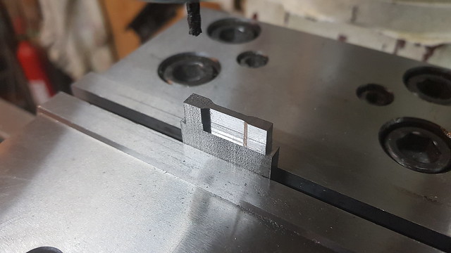 20190818_185304 20190818_185304 by Timothy Froud, on Flickr The 1.6mm slot was put in with a 1.5mm cutter  20190819_080403 20190819_080403 by Timothy Froud, on Flickr The stock was set centrally using the wobbler on the sides. This is the same way it was set up in the other orientation. That makes it easy to register one orientation to the other. The machining was done in two heights, the whole profile down to a level which leaves the middle section attached, and the full depth leaving the lug in the middle...  20190819_082351 20190819_082351 by Timothy Froud, on Flickr ... so it ends up like this.  20190819_092823 20190819_092823 by Timothy Froud, on Flickr The link was attached to the shaft with Loctite and then pinned with a 1mm Stainless pin which is peened over to make it permanent. 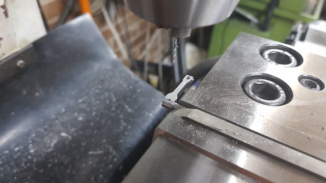 20190820_195716 20190820_195716 by Timothy Froud, on Flickr  20190820_200156 20190820_200156 by Timothy Froud, on Flickr The whole thing was assembled onto the locomotive and a blob of Loctite added to the end of the shaft to hold it while it was being pinned.  20190820_204635 20190820_204635 by Timothy Froud, on Flickr This is how it looks with the pin engaged with the grate...  20190820_205831 20190820_205831 by Timothy Froud, on Flickr ... and released. You can see that I've put a flat on the pin that secures the grate, and added a long pin that sticks out to one side. This is necessary because the boiler and ashpan aren't precisely on the centre line which is where the mechanism is. The long pin means that it can find it's own position on the link so it doesn't bind.  20190820_205958 20190820_205958 by Timothy Froud, on Flickr Having fixed the other end to the shaft and pinned, it was clear that it would be better if the pin was slightly further in when the grate was locked. The easiest way to fix that was to make a slightly longer link.  20190820_214752 20190820_214752 by Timothy Froud, on Flickr That fixed the issue to it now works are needed. |
|
|
|
Post by Oily Rag on Aug 21, 2019 20:59:20 GMT
I have gone all dizzy while following Roger's rocking grate mech. 
|
|
|
|
Post by Roger on Aug 21, 2019 21:55:36 GMT
The 4mm x 50mm x 500mm gauge plate arrived today, so here it is being set up for machining the Reach Rod. The edge is clocked straight and the centre found front to back. The holes in the end are drilled and reamed first so that I can easily set it back up if there's a power cut or something that goes wrong.  20190821_112929 20190821_112929 by Timothy Froud, on Flickr I'm machining it with a 3mm 4 flute cutter because that's pretty rigid for the depth I'm cutting (4mm) but I'm only taking 0.5mm deep cuts and 25mm/min. It's going to take a long time, so I need to know that it's not going to run into trouble. Taking easy cuts that are running sweetly just makes life easier in the long run. There's no rush, I've got other things I need to be doing today. This is how it looks after three passes. I'll vacuum that up since I'm here.  20190821_124626 20190821_124626 by Timothy Froud, on Flickr  20190821_155612 20190821_155612 by Timothy Froud, on Flickr I've left 15mm long nibs, 1mm high every 40mm to make sure it's well supported. You can see how that looks here.  20190821_200226 20190821_200226 by Timothy Froud, on Flickr Being Gauge Plate that takes a bit of cutting out...  20190821_202302 20190821_202302 by Timothy Froud, on Flickr ... and even more to tidy it up, but here is is finished. There's a bush to go at the reverser end which I'll make soon. along with the pivot pin. It's possibly a bit chunky, but it's mostly hidden under the tank so it won't show. I wanted it to be really rigid because I could see how much it all tried to flex when I had the chassis running on air. I don't want any more movement of the Reach Rod than I can possibly avoid. If it does look a bit chunky from the top, I'll chamfer it at a shallow angle on the top so the visible edge looks thinner.  20190821_220025 20190821_220025 by Timothy Froud, on Flickr |
|
dscott
Elder Statesman

Posts: 2,438
|
Post by dscott on Aug 22, 2019 1:12:41 GMT
When all your Relatives have filled up their LIMIT on Flikr what happens?
Yes Gauge plate is a wonderful material! I sometimes find myself chatting to Noggin end metals about the more exotic end of steels for highly stressed parts. Often when I do not want to go to the trouble of case hardening and cleaning up again.
Then it is on to Tracy Tools or Greenwood for something to machine it with!!!
David, relaxing after searching for suitable cable for connecting 2 12 volt batteries together 3 feet apart to make 24 volts!!!
AND Driving to the other side of Reading to pick up an internet purchase of LETTER DRILLS in a holder! It would have been quicker to WALK!!!
|
|
|
|
Post by Roger on Aug 22, 2019 5:45:58 GMT
When all your Relatives have filled up their LIMIT on Flikr what happens? Yes Gauge plate is a wonderful material! I sometimes find myself chatting to Noggin end metals about the more exotic end of steels for highly stressed parts. Often when I do not want to go to the trouble of case hardening and cleaning up again. Then it is on to Tracy Tools or Greenwood for something to machine it with!!! David, relaxing after searching for suitable cable for connecting 2 12 volt batteries together 3 feet apart to make 24 volts!!! AND Driving to the other side of Reading to pick up an internet purchase of LETTER DRILLS in a holder! It would have been quicker to WALK!!! Hi David, Well, then I move on to husbands, partners, friends etc. I don't anticipate running out before it's finished. |
|
uuu
Elder Statesman
your message here...
Posts: 2,812
|
Post by uuu on Aug 22, 2019 6:23:19 GMT
Deceased ancestors might work.
Wilf
|
|
|
|
Post by jon38r80 on Aug 22, 2019 9:59:32 GMT
You must have much better glasses than me! I think its time to go to the opticians for an eye test and new glasses.
|
|
|
|
Post by Roger on Aug 23, 2019 19:16:52 GMT
The Reach Rod needs a 9mm joggle from end to end, and that's about 1.6 degrees at each end. The idea with this setup is to hold the rod between the jaws protected by paper and to put a little pre-tension in the desired direction before using the mallet and white Delrin block to effect the bend. That might seem a little odd at first, but it prevents the main part of the rod getting a reverse bend. If you hit it when it's flat, it will bend at the vice and also at the point beyond the end of the Delrin block. The same process was repeated on the other end and the offset checked against a straight edge. It's impossible to get this dead right, but it can be close.  20190823_111946 20190823_111946 by Timothy Froud, on Flickr The pole reverser has a 3mm pin attached to it to provide the pivot point. The Reach rod will be retained with a washer and split pin.  20190823_183000 20190823_183000 by Timothy Froud, on Flickr I bought this 1.5mm wide parting tool at the Great Dorset Steam Fair with a box of inserts for £35. Not the cheapest, but I really liked the fact that the side next to the chuck is flat.  20190823_183255 20190823_183255 by Timothy Froud, on Flickr This is the bearing sleeve that goes in the end of the reach rod at the pole reverser end. It's made from Vesconite which is a dry bearing material, the same I've used for experimental bearings on the connecting rod. The reason for this odd choice lies in my attempt to reduce the lost motion in the reversing mechanism. I can make the sleeve size for size without any clearance and yet it will still turn.  20190823_193100 20190823_193100 by Timothy Froud, on Flickr These are the parts ready for fitting. The flange on the back of the bearing makes sure it doesn't come out when the rod is pushed onto the pin. I noticed there's a burr on that and tidied it up with a scalpel before fitting!  20190823_193455 20190823_193455 by Timothy Froud, on Flickr I'd ground the pin to get a sug fit, and it's ended up as a press fit in the pole reverser. The vise is pressing this home using a block with a 3mm hole in it. I was going to Loctite this, but it's not necessary because it's nice and tight.  20190823_194616 20190823_194616 by Timothy Froud, on Flickr This is how it looks assembled.  20190823_195956 20190823_195956 by Timothy Froud, on Flickr |
|
twombo
Seasoned Member
Posts: 119 
|
Post by twombo on Aug 23, 2019 20:43:30 GMT
David. Regarding your Battery cable question. Here is a handy calculator. www.calculator.net/voltage-drop-calculator.html I have an off the grid solar power system and 1% voltage drop is. Preferred. For. A small locomotive it is a cost vs efficiency determination. Lower losses to cable heating gives you more time. On the track! I have a battery powered project hiding in the corner of my workshop, so your question is one that has been on my mind. roger. Your reverser stand is an inspiration. Rarely have I seen a tension spring so neatly done! Your efforts to reduce “play” in the mechanism will pay off in so many ways! Super job! Mick |
|
dscott
Elder Statesman
Posts: 2,438
|
Post by dscott on Aug 24, 2019 0:55:30 GMT
As usual Roger you should have done TWO of them and mounted the other on the Mantelpiece!
I have in my collection a crank which is so SUPERB it should be on display.
Crisp and polished almost mirror like.
David and Lily.
|
|
|
|
Post by Roger on Aug 25, 2019 20:44:47 GMT
Todays job is to make the lever on the right of the picture. In full size, I believe this operates the front sanding gear, but I'm going to use it to operate the valve that selects water from the riding truck or balance pipe for the inlet to the axle pump. Just a reminder of what that's about... the Pannier Tanks feed both the axle pump and the two injectors. When using the riding truck to supply water, that's a problem. Usually the injectors are fed directly from the riding truck, but I can't do that and keep a scale appearance. My solution is to allow the axle pump to transfer water from the riding truck by connecting its input to that supply. This opens many possibilities for running, with or without a riding truck supply. The lever will allow the amount of water drawn from the riding truck to be regulated if required. Alternatively, the maximum delivery of the pump can transfer water to the Pannier Tanks so you can fill them up on the run. This is the reason I wanted to have the water level guages available so I can see when the tanks are full.  20140204_113216 20140204_113216 by Roger Froud, on Flickr The lever is being made from 1.5mm thick Gauge Plate so it can be as slender as possible. However.... this is what happens if you don't clamp it down tightly enough!  20190825_083242 20190825_083242 by Timothy Froud, on Flickr So this is one good one and one scrap one!  20190825_092851 20190825_092851 by Timothy Froud, on Flickr The end is getting a 1mm hole for a piece of Silver Steel rod that will locate the handle while it's being Silver Soldered on. It will also give it more strength. I'm starting the hole with a 0.8mm PCB drill then switching to a 1mm HSS drill. PCB drills are great, but you don't want to break one off by going too deep!  20190825_205510 20190825_205510 by Timothy Froud, on Flickr The Aluminium piece was machined to assist getting the shape right. I've added a 1.6mm hole for a pin to make sure the bend starts in the right place. It's important it's right, the space for it is very restricted.  20190825_211146 20190825_211146 by Timothy Froud, on Flickr I've used a piece of round Delrin bar to tap this into place with a mallet. However, there's always going to be spring back...  20190825_211512 20190825_211512 by Timothy Froud, on Flickr ... so this is the setup for squeezing it round a little more by hand...  20190825_211712 20190825_211712 by Timothy Froud, on Flickr ... so it fits closely enough.  20190825_211815 20190825_211815 by Timothy Froud, on Flickr The lever pivots on a tiny bracket that bolts down onto the cab floor and it mostly hidden by the chequer plate. This is a piece of 14mm Mild Steel being roughed with a 2mm cutter, finished with a 1mm to get into the corners. 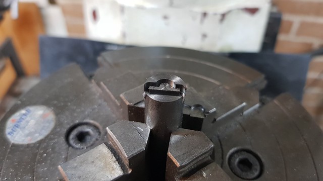 20190825_193057 20190825_193057 by Timothy Froud, on Flickr The fixing holes are M1.4  20190825_201517 20190825_201517 by Timothy Froud, on Flickr It ends up like this.  20190825_202701 20190825_202701 by Timothy Froud, on Flickr |
|
timo
E-xcellent poster
Completing 3 1/2 Rainhill .Building 5" Railmotor and waiting to start 3 1/2" King
Posts: 234
|
Post by timo on Aug 25, 2019 21:12:38 GMT
Amazing stuff Roger. If I was trying to do that I would have to buy those drills by the gross!
Tim
|
|
|
|
Post by silverfox on Aug 25, 2019 21:30:07 GMT
Roger
Can you remember who you got the parting tool from
It looks a bit more sturdier than the one i have.... and it is cheaper!!!
Ron
|
|
|
|
Post by Roger on Aug 26, 2019 7:14:37 GMT
Amazing stuff Roger. If I was trying to do that I would have to buy those drills by the gross! Tim Hi Tim, It's not hard using them really, you just need a wheel feed and go very slowly, pulling the drill out every 0.3mm say. The biggest risk is when you go back down to start the next cut. I use the DRO on the quill to watch that like a hawk, remembering exactly how deep I am for each peck. I won't say that I never break them, but it doesn't happen very often. |
|
|
|
Post by Roger on Aug 26, 2019 7:17:19 GMT
Roger Can you remember who you got the parting tool from It looks a bit more sturdier than the one i have.... and it is cheaper!!! Ron Hi Ron, That one came from a tool stall at the Great Dorset Steam Fair on Thursday. There were several places selling the same style in the Auto Jumble. I like the fact that it's fairly chunky for a small tool and that you can get up close to the chuck. The other type I have with the HSS blade gets in the way of the chuck. One day I'll make a better tool holder for those. |
|
|
|
Post by 92220 on Aug 26, 2019 7:48:40 GMT
Amazing stuff Roger. If I was trying to do that I would have to buy those drills by the gross! Tim Hi Tim, It's not hard using them really, you just need a wheel feed and go very slowly, pulling the drill out every 0.3mm say. The biggest risk is when you go back down to start the next cut. I use the DRO on the quill to watch that like a hawk, remembering exactly how deep I am for each peck. I won't say that I never break them, but it doesn't happen very often. Hi Roger. I must remember that tip for the smallest drills. The smallest that I have used so far if 0.6mm drilling down 0.125 ins in mild steel and using the hand feed VERY gently. I'd not thought of using the DRO. I must relocate my display to make it easier to see when drilling very small holes. That reverser lever is a work of art!!! Bob. |
|
|
|
Post by Roger on Aug 26, 2019 9:00:35 GMT
Hi Tim, It's not hard using them really, you just need a wheel feed and go very slowly, pulling the drill out every 0.3mm say. The biggest risk is when you go back down to start the next cut. I use the DRO on the quill to watch that like a hawk, remembering exactly how deep I am for each peck. I won't say that I never break them, but it doesn't happen very often. Hi Roger. I must remember that tip for the smallest drills. The smallest that I have used so far if 0.6mm drilling down 0.125 ins in mild steel and using the hand feed VERY gently. I'd not thought of using the DRO. I must relocate my display to make it easier to see when drilling very small holes. That reverser lever is a work of art!!! Bob. Hi Bob, When you say 'hand feed' I presume you do mean a wheel. I don't think it's feasible with a hand lever. That's pretty deep with a 0.6mm PCB drill, although perfectly possible as you've demonstrated. Unless there's a compelling reason to go that deep with carbide, I tend to switch to HSS to finish them off, simply because breaking a carbide drill can easily scrap the job. You can drill or a HSS drill with a carbide one thouth. Another thing to watch out for is runout with carbide. They're so much moor rigid than HSS that you can end up drilling over size of the material is soft. Sometimes you're better off having a flexible drill, and a rigid one at others. |
|


