stevep
Elder Statesman

Posts: 1,070
|
Post by stevep on Nov 24, 2019 19:45:55 GMT
Looking stupendous, Roger.
|
|
|
|
Post by David on Nov 24, 2019 22:30:45 GMT
Really nice. I'm glad I'm not the only one who has flat parts coming off the machine looking like your box parts! Are they held to the parent stock by tabs?
|
|
|
|
Post by Roger on Nov 25, 2019 8:10:04 GMT
Really nice. I'm glad I'm not the only one who has flat parts coming off the machine looking like your box parts! Are they held to the parent stock by tabs? Thanks David, CNC is so useful for sheet metal parts, but anyone thinking it's just going to need a coat of paint afterwards is going to be disappointed! Yes, I've machined the final profile cuts to the full depth which always leaves a wafer at some point on the profile, and there are four shallow sloping tabs 1mm high and 15mm long holding it in place. Making them really long helps to prevent breakages. The total depth is 1.8mm but I take a first roughing cut at 0.6mm deep all round so that the approach cut for the bumps can be on an edge. I thought that would give the cutter an easier time. I machine it to the full depth and add the finishing cut once the bumps have been finished. You can't do the profile to the full depth before the bumps because the sheet is prone to lifting. You can see that happen by the way the cut is visible on the reverse side, which shows it must have lifted the surrounding metal slightly. |
|
|
|
Post by 92220 on Nov 25, 2019 9:16:48 GMT
Hi Roger.
That chequer has come out really well. I would never have thouight it possible, but it looks just as good as the etched sheet I have!!
Bob.
|
|
|
|
Post by Roger on Nov 25, 2019 21:47:37 GMT
Hi Bob, It's come out surprisingly well considering how it's done. I think this is easier to machine than the Admiralty style you have which would have a less pronounced corner in the diamond pattern with the 1mm cutter. It could be done with engraving tools but I reckon it would take twice the time which is already pretty long. Anyway, here's the second plate which has been a struggle today. I thought I'd be ok to use 200mm/min for the finishing pass since the cut is pretty light, but that proved to be too fast and the cutter broke. I then tried a slower 150mm/min pass and that broke too. So I dropped it way down to around 70mm/min rather than break another one and run out of time to finish it in one pass. That worked fine, but it takes too long. I think that ran for around 8-9 hours.  20191125_211751 20191125_211751 by Timothy Froud, on Flickr So the answer is to increase the spindle speed which is limited with the large spindle. It's noisy and doesn't do the spindle much good, so I can't run it flat out anyway. You've seen this long ago, but not in kit form. I designed and machined this many years ago when I thought I'd use it a lot. As it happens, it's not been that useful since it's possible to do most things by just taking a bit more time. However, there's a lot of machinging still to do on these so this ought to make all the difference. The spindle is from a Systems Efficiency R100 belt driven router that I'm still involved in supporting in the field. On that machine it's driven by a Poly-Vee belt that goes around two spindles and it's driven by a large flat pulley on a 50Hz 3-phase motor. You can see how small the pulley is on these, and that gave 24,000RPM, not bad for greased bearings. The highest speed we ever did with greased bearings was 80,000RPM and that's a challenge to get them run in. But I digress.... You can see how short this Poly-Vee belt is, and that's a problem because repeatedly flexing that and straightening it out around the spindle creates an awful lot of heat, enough to melt the belt! You can see a heatsink on the top of the spindle to cool the shaft, and that was sufficient cooling on the big machine to prevent the top bearing from cooking. However, I've had to introduce a fan to draw in air from the bottom of the motor mount and blast it out over the belt to keep it cool.  20191125_195300 20191125_195300 by Timothy Froud, on Flickr The fan was robbed from a PC fan and an adaptor added to the motor pulley. I take it off when it's used on the grinder because the belt is much longer so it has less flexing cycles and doesn't get that hot.  20191125_195821 20191125_195821 by Timothy Froud, on Flickr The motor is one designed for a Centrifuge so it's good for 9000RPM, way faster than most Squirrel Cage motors. Running that with a VFD allows variable speed control from the knob on the front and now also from the CNC controller. I can get 24000RPM if necessary, but I've never used that on here. It's surprising how much noise all that moving air makes so there's a limit to how fast I can go. The belt isn't tight, it doesn't need to be because the speed is so high that it flies outwards and isn't ever going to slip.  20191125_200033 20191125_200033 by Timothy Froud, on Flickr Anyway, watch this space, we'll see what difference it makes. |
|
|
|
Post by 92220 on Nov 26, 2019 9:21:03 GMT
First time I've seen that Roger. A very clever idea and handy addition for the mill!! I have a tile grinder that runs up to 33k revs and have wondered about adapting that for tiny cutters. It already comes with a collet on the nose. I must look at a way to mount it as it is designed as a hand held tool.
Bob.
|
|
|
|
Post by Roger on Nov 26, 2019 11:19:14 GMT
This is the second plate finished. The edge has been machined to give the impression that the plate is much thinner than it actually is.  20191126_095617 20191126_095617 by Timothy Froud, on Flickr I need to make sure that all of these are going to fit with the bunker in place, so that's going to stay on for while.  20191126_095641 20191126_095641 by Timothy Froud, on Flickr The high speed spindle could really use to be a fair bit lower than it currently is. I've been thinking about modifying it for some time, but now it's probably worth doing something about it. It's not a problem with this cutter which has a long shank though.  20191126_084929 20191126_084929 by Timothy Froud, on Flickr Here's a wobbly video of the roughing pass. This was machined at 9000RPM and 200mm/min and it made pretty short work of it and much quieter than using the main spindle.  20191126_100030 20191126_100030 by Timothy Froud, on Flickr  20191126_100707 20191126_100707 by Timothy Froud, on Flickr This is a wobbly video of the finishing pass. This setup was a problem though, I've had to hang both the holder and the cutter far more than I'd like and I can only just reach the surface even now.  20191126_104319 20191126_104319 by Timothy Froud, on Flickr So I've turned down a second spacer that I had for the spindle to move it down 18mm in the body. That will leave the heatsink on the top of the spindle just clear of the mount. The legs on the motor mount are 15mm so I'll have to lose those and a further 3mm to bring the motor down. That would block off the air supply to the fan and the end of the motor would foul the mount, so that will need a big clearance hole to be added to solve that problem. That ought to transform the situation though, so it's well worth doing. I could also get another 1mm or so by machining the bottom of the mount where it attaches to the quill so that the whole arrangement was 1mm lower. Anyway, I've ordered the longer bolts and I'll modify it as soon as they arrive. |
|
|
|
Post by simplyloco on Nov 26, 2019 11:34:42 GMT
Well impressed Roger: you are just handing us these super techniques on a plate!  John |
|
don9f
Statesman
 Les Warnett 9F, Martin Evans “Jinty”, a part built “Austin 7” and now a part built Springbok B1.
Posts: 960 
|
Post by don9f on Nov 26, 2019 19:23:38 GMT
Hi Roger, the roughing wobbly video worked ok for me, but the link to finishing one just took me to the current page 572 of the thread....
Any chance you could check the link?
Thanks Don
|
|
|
|
Post by Roger on Nov 26, 2019 21:02:17 GMT
Hi Roger, the roughing wobbly video worked ok for me, but the link to finishing one just took me to the current page 572 of the thread.... Any chance you could check the link? Thanks Don Sorry about that Don, try it now. |
|
don9f
Statesman
Les Warnett 9F, Martin Evans “Jinty”, a part built “Austin 7” and now a part built Springbok B1.
Posts: 960
|
Post by don9f on Nov 26, 2019 21:21:28 GMT
👍
|
|
|
|
Post by Roger on Nov 26, 2019 21:53:06 GMT
I didn't want to push my luck and break the cutter part way through, so I used 150mm/min instead of the 200 I was going to use. When the cutter can be used with less overhang, I'll speed it up a bit. This only took around five hours to complete, so that's not too bad.  20191126_170625 20191126_170625 by Timothy Froud, on Flickr  20191126_185951 20191126_185951 by Timothy Froud, on Flickr You can see where the nibs are from the pattern on the back.  20191126_190139 20191126_190139 by Timothy Froud, on Flickr  20191126_213428 20191126_213428 by Timothy Froud, on Flickr This highlights a couple of problems. The bunker door slides are too low, I forgot to allow for the plate thickness, so those will need trimming down. More annoying is that rear plate I made yesterday is 0.2mm too big all round because I'd forgotten to change the Roughing stock to zero and also neglected to measure it. I'll have to pop that in the vice and knife and fork that reduction. Other than that, it looks ok.  20191126_213856 20191126_213856 by Timothy Froud, on Flickr Here's the clearance hole for the fan going into the spindle mount...  20191126_203737 20191126_203737 by Timothy Froud, on Flickr ... and here are the modified parts for bringing the spindle a full 18mm down. That's going to make a world of difference. You can see just how short that Poly-Vee belt is from here and why that's a problem when it has to be flexed back and forth so often.  20191126_210340 20191126_210340 by Timothy Froud, on Flickr |
|
|
|
Post by David on Nov 26, 2019 21:57:51 GMT
I hadn't seen the bunker before, that looks very good. Interesting high speed spindle too.
|
|
|
|
Post by Roger on Nov 27, 2019 22:50:54 GMT
Unfortunately, the Mill has been tied up way too much recently on commercial jobs, so I've not had much opportunity to get things done on the locomotive. I've finished all of the outstanding jobs for the time being, so the high speed spindle is getting its first outing since dropping the spindle 18mm. It's a huge improvement, and well worth the effort. I decided to machine the edge rather than try to file it. It will be more accurate and frankly won't take any longer. So all I've done is to clamp some backing material and drill the 1mm dummy bolt holes that will register the plate to the profile. The clamps holding the backing material aren't moved during the following process.  20191127_203707 20191127_203707 by Timothy Froud, on Flickr I've used some 1mm bolts to line it up and then used my skinny clamps for holding the plate down. This is trimming the edge rebate with a 1mm cutter. This part looked ok, but I thought I'd make sure.  20191127_205827 20191127_205827 by Timothy Froud, on Flickr Then it was just a matter of creating a profile without the nibs to the full depth in one cut and moving the clamps out of the way while it was still crawling around the edge.  20191127_212736 20191127_212736 by Timothy Froud, on Flickr  20191127_212913 20191127_212913 by Timothy Froud, on Flickr  20191127_213103 20191127_213103 by Timothy Froud, on Flickr You can see just how much more of the spindle it sticking down below the quill now.  20191127_213329 20191127_213329 by Timothy Froud, on Flickr  20191127_213446 20191127_213446 by Timothy Froud, on Flickr .... and that's all the was to it. Simple really.  20191127_213658 20191127_213658 by Timothy Froud, on Flickr |
|
|
|
Post by Roger on Nov 28, 2019 22:36:33 GMT
Cutting the coal door slides down manually was going to be a nightmare, so I opted to machine them down to a wafer thickness instead. The high speed spindle can go up to 1/4" cutters, so my stubby 5.5mm ones were ideal for this.  20191127_223340 20191127_223340 by Timothy Froud, on Flickr Here's a wobbly video of the not so high speed spindle in action.  20191127_223348 20191127_223348 by Timothy Froud, on Flickr There was barely 0.1mm left to remove, so getting a scalpel blade under them was all it took to break those off.  20191128_222355 20191128_222355 by Timothy Froud, on Flickr |
|
|
|
Post by Roger on Nov 28, 2019 22:59:49 GMT
I thought I'd try a plate without pre-cutting the outside and although it did manage it, the noise at the end of each sweep as it reversed told me it wasn't happy.  20191128_104227 20191128_104227 by Timothy Froud, on Flickr I won't be doing that again. Here's the 0.6mm deep cut ready for the finishing pass with the 1mm ball nosed cutter. I've been really impressed with these. They were really cheap and were on 1mm shanks since ball nosed cutters aren't used in the PCB industry and they didn't need to be on a 1/8" shank 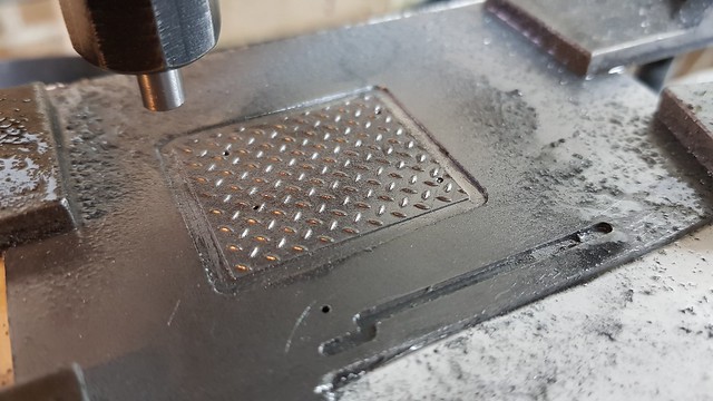 20191128_133934 20191128_133934 by Timothy Froud, on Flickr I'm using up some offcuts from other parts since this isn't a very large plate. I don't worry about cleaning up swarf as I go, it's really not necessary for something like this.  20191128_142240 20191128_142240 by Timothy Froud, on Flickr  20191128_142354 20191128_142354 by Timothy Froud, on Flickr This is yet another plate... 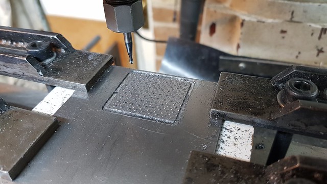 20191128_154346 20191128_154346 by Timothy Froud, on Flickr Yet another wobbly video, this time showing the difference the high speed spindle makes to the possible feedrates. This is running at 16000RPM and 250mm/min and it could probably go a fair bit faster. I've only got about 1mm of the 1mm ball nosed cutter protruding from the holder, so it's very rigid. 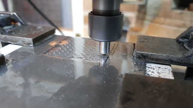 20191128_160211 20191128_160211 by Timothy Froud, on Flickr ... it's the front LH one in this picture. You can see that the long plate now fits under the coal door slide. Things are all a bit tight, but it's not surprising since it's all machined to exact sizes. The plates will have to be eased to get the right fit once the base plate have been made.  20191128_222736 20191128_222736 by Timothy Froud, on Flickr One final plate today, that's three altogether, quite an improvement in productivity!  20191128_222748 20191128_222748 by Timothy Froud, on Flickr |
|
don9f
Statesman
Les Warnett 9F, Martin Evans “Jinty”, a part built “Austin 7” and now a part built Springbok B1.
Posts: 960
|
Post by don9f on Nov 28, 2019 23:24:55 GMT
Again, absolutely fantastic!
Don
|
|
44767
Statesman
Posts: 529
|
Post by 44767 on Nov 29, 2019 9:32:47 GMT
That all looks fantastic, Roger! Have you ever considered using double sided sticky tape for holding this sort of work to the table? We used it a lot at work for this sort of work. Not to do with your topic, other than the use of small cutters. This is a picture of the tooling I'm making to injection mould the waxes for the handle for my little machine vice. To get the lettering sharp enough I used a Ø0.3mm end mill to do the finish profile of the core. I am now not afraid of 1mm cutters!  This is the first shot from the tool.  |
|
|
|
Post by Roger on Nov 29, 2019 10:03:38 GMT
That all looks fantastic, Roger! Have you ever considered using double sided sticky tape for holding this sort of work to the table? We used it a lot at work for this sort of work. Not to do with your topic, other than the use of small cutters. This is a picture of the tooling I'm making to injection mould the waxes for the handle for my little machine vice. To get the lettering sharp enough I used a Ø0.3mm end mill to do the finish profile of the core. I am now not afraid of 1mm cutters! This is the first shot from the tool. Hi Mike, I've used double sided tape in the past, but although it's great at holding things down, it can be problematical getting them off afterwards. I've since bought some Label Remover solvent that might just help with that though. I find that my skinny low profile clamps are usually good enough because I'm not machining large areas. Maybe using small strips of double sided tape would be a compromise for those kinds of jobs. That's a lovely mould. I've used 0.5mm cutters on mine, but never 0.3mm. I'd certainly have to use the high speed spindle to have a realistic chance of using that small a size. You can now buy PCB drills down to 50microns if you're looking for a new challenge! |
|
44767
Statesman
Posts: 529
|
Post by 44767 on Nov 29, 2019 10:19:10 GMT
It can be a problem getting parts off. You certainly don't need as much as you'd think. I often stick them to a plate which can be unclamped and the parts pushed off through holes from the back. Or, on the grinder, I would tape them to transfer blocks which in turn are held by the magnet.
Cheers, Mike
|
|