uuu
Elder Statesman
 your message here...
Posts: 2,808
|
Post by uuu on Apr 24, 2024 16:26:44 GMT
I had a damaged MT2 taper on a lathe - a friend lent me a reamer of the right size and that fixed it. OK, I expect grinding would have delivered a better result, but I was happy with the quick fix.
Wilf
|
|
uuu
Elder Statesman
your message here...
Posts: 2,808
|
Post by uuu on Apr 15, 2024 18:35:07 GMT
And...
I have wondered on my own loco (Ken Swan's Jessie) why the clacks for axle pump and injector are different. The injector one uses a 3/16" ball and the pump has 1/4". So - if you use O-ring valves, should they also be of different sizes?
Wilf
|
|
uuu
Elder Statesman
your message here...
Posts: 2,808
|
Post by uuu on Apr 12, 2024 13:12:47 GMT
In the future you could consider upgrading to a three-phase motor with an inverter to provide variable speed. When I've gone this route I've kept my eyes open on ebay for both motor and inverter (separately) to come up cheaply.
Wilf
|
|
uuu
Elder Statesman
your message here...
Posts: 2,808
|
Post by uuu on Apr 12, 2024 13:09:43 GMT
I would not expect the extra capacitor is related to reversing the motor. It may be you have a "capacitor-start-capacitor-run" motor, that uses one capacitor all the time and another only when starting. This would exhibit a characteristic "click" as the motor slows down on turn-off. See description here: www.electricity-magnetism.org/capacitor-start-capacitor-run-induction-motor/Wilf |
|
uuu
Elder Statesman
your message here...
Posts: 2,808
|
Post by uuu on Apr 11, 2024 11:24:16 GMT
I've had a go opening one of your images in IBB. Scrolling down I get a section headed "embed codes" and there's a box with BBCode in it. Copying and pasting into a reply here (not pressing any buttons here - just paste in the code) - I get this :  Wilf |
|
uuu
Elder Statesman
your message here...
Posts: 2,808
|
Post by uuu on Apr 8, 2024 10:03:09 GMT
Just another thought in support of separate feeds (although as OldNorton says, shared axle/hand pump feed will work):
Boiler feed issues are infuriating. Six people will gather round and each will have a different idea as to the cause. Diagnosis is much easier if you can halve the number of areas to investigate.
Wilf
|
|
uuu
Elder Statesman
your message here...
Posts: 2,808
|
Post by uuu on Apr 8, 2024 7:12:55 GMT
Ideally separate - when shared each pump will rely on the others valves to prevent back-flow. So when one pump fails, the other can become ineffective too. But I've seen it done. So I've the boiler is not yet made, I'd add an extra bush - but no point trying to retro-fit one. I've also seen two clacks side-by-side screwed into a single boiler bush - borrowing a John Baguley picture here: 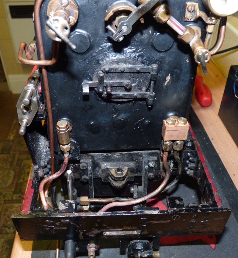 Wilf |
|
uuu
Elder Statesman
your message here...
Posts: 2,808
|
Post by uuu on Mar 31, 2024 10:18:16 GMT
My daughter saw a "fidget toy" online - but the cost of shipping from the US was prohibitive - so she asked me to make her one. It was just a switch mounted in a block of plastic, that you could click to keep your hands occupied in meetings etc. Here's what I made:  20240330_124810 20240330_124810 by Wilf, on Flickr It's just two blocks of aluminium hollowed out and spigoted together. To dress it up, I added a band of bronze (from John at the Pumphouse) around it. It is pressed together - but with a dab of Loctite to make it more secure. If I made it again, I might use three shorter blocks. You can see scoring on the sides where my milling cutter was a little too short and the area above the flutes (near the joint) rubbed. Wilf |
|
uuu
Elder Statesman
your message here...
Posts: 2,808
|
Post by uuu on Mar 19, 2024 19:05:19 GMT
Myford spindle will take MT2 (if I remember right - I sold mine a while ago) - so no need for a four jaw - just plug in.
Wilf
|
|
uuu
Elder Statesman
your message here...
Posts: 2,808
|
Post by uuu on Mar 18, 2024 22:33:33 GMT
Also. Having an MT2 one will fit in both sides of the Myford, Which might be handy.
You can't use an MT2/MT3 adaptor if it's designed for tooling with tangs - or itself has a tang. You absolutely must have the chuck held up by a drawbar.
You can get a screw-in tang to adapt a drawbar tool to fit, for example, the Myford tailstock.
Wilf
|
|
uuu
Elder Statesman
your message here...
Posts: 2,808
|
Post by uuu on Mar 18, 2024 22:12:13 GMT
They do come up for sale occasionally - here's one: www.ebay.co.uk/itm/315135882758 It's only got two collets - but they also come up. I wouldn't try to alter the spindle. Much safer to play with the tooling. I don't know how hard the surface of the taper is - I'd be looking to buy what you need. There the "Posilock" chuck, which does the same job: www.ebay.co.uk/itm/285480704662Wilf Edit - I think the small size Autolock chucks may not take collets to fit a 1" cutter. Need to check. You may struggle to find any style of collet chuck that cn fit that size cutter onto an MT2 shank. What you may be able to do is to buy a blank-ended arbour on an MT2 shank and bore it 1" - with a clamping screw. Although I'm struggling to find an arbour with a big enough stub. |
|
uuu
Elder Statesman
your message here...
Posts: 2,808
|
Post by uuu on Mar 18, 2024 13:07:05 GMT
Hello!
I don't think there is a specific topic board - I suppose the Tools and Tooling section would be the best place to start a thread - or just pose a question right here while you have our attention.
I had a Centec, and used an Autolock chuck with it. Decent machine. I've switched over to using ER25 collets to hold tools - they are more versatile, as they can hold plain cutters as well as threaded. I've not found pull-out to be a problem. And you can hold drills in them, gaining a bit more space under the spindle, compared with a drill chuck. My 2A was lacking in space.
Wilf
|
|
uuu
Elder Statesman
your message here...
Posts: 2,808
|
Post by uuu on Mar 12, 2024 10:53:55 GMT
Ah - you've hit the snag with this site. You can't upload pictures directly - you have to save them first to an image hosting side like Flickr, and then link them in. There's a thread about it here: modeleng.proboards.com/thread/1627/post-picsWilf |
|
uuu
Elder Statesman
your message here...
Posts: 2,808
|
Post by uuu on Mar 11, 2024 8:47:52 GMT
When fitting motors with a different shaft diameter, I have managed to bore out the existing pulley, or make a bush. Also be aware the foot or flange holes may be spaced differently.
The lathe at the club has a horrible conversion (not done by me) - the whole motor is physically bigger than standard, so the shaft is further away from the foot. This meant enlarging the hole into the belt casing to stop it rubbing - and it doesn't hinge as easily for belt tension adjustment.
Wilf
|
|
uuu
Elder Statesman
your message here...
Posts: 2,808
|
Post by uuu on Mar 9, 2024 7:27:25 GMT
I'm a big fan of three-phase motors and inverters. Yes, this could mean more expense, but I've had success sourcing these on ebay. My current lathe has a lovely Siemens motor - new-old-stock - and a fine Mitsubishi inverter, second hand, but fully working. I've had half a dozen of the same inverter - all off ebay. Patience is needed - there are many listings at silly money, but wait a bit and the right one will come up cheap.
Wilf
|
|
uuu
Elder Statesman
your message here...
Posts: 2,808
|
Post by uuu on Mar 8, 2024 10:24:29 GMT
For the valvegears I've been playing with, I use File-SaveAsDimensions before closing. This creates a .dso file with all the settings - then I use File-OpenDimensions to retrieve them later. This allows me to save multiple versions of the design I'm working on.
Wilf
|
|
uuu
Elder Statesman
your message here...
Posts: 2,808
|
Post by uuu on Mar 7, 2024 7:49:12 GMT
I run Docksteader on my Windows 10 machine with no problems.
Wilf
|
|
uuu
Elder Statesman
your message here...
Posts: 2,808
|
Post by uuu on Feb 26, 2024 9:04:30 GMT
And - here's an illustration from Don Ashton's page ( web.archive.org/web/20190919220645/http://www.donashton.co.uk/html/stephenson_s_gear.html):  Where he says: "...The illustration shows wrong thinking on two scores. Firstly, the square symmetry of the reversing arrangement cannot accommodate angularity errors at all..." And - here's the killer quote: "...Therefore the lifting link is highly unlikely to be vertical, though few traction engine designers seemed to realise this!..." Wilf |
|
uuu
Elder Statesman
your message here...
Posts: 2,808
|
Post by uuu on Feb 26, 2024 8:47:29 GMT
I don't think the lifting link has to be vertical. I can't find evidence of your arrangement, but a locomotive example below is not vertical: 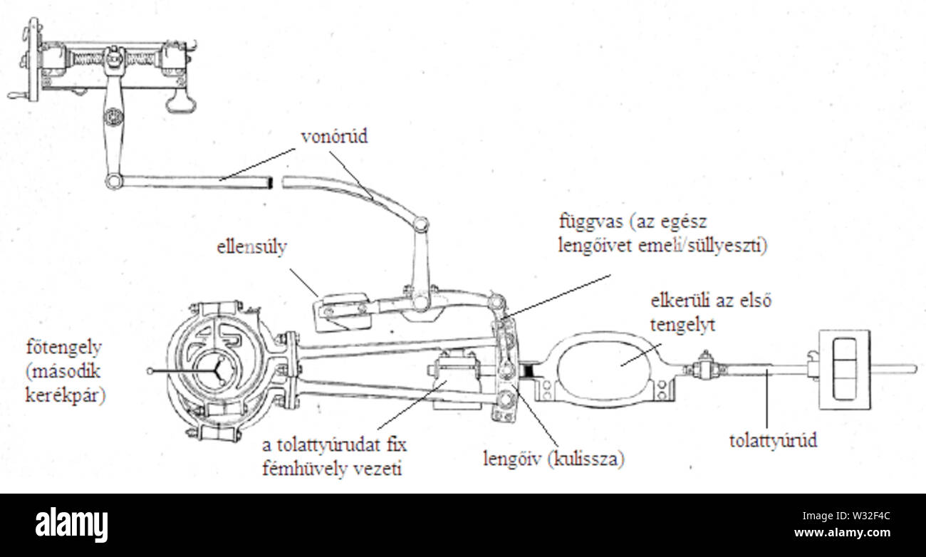 And here's another, not quite upright: 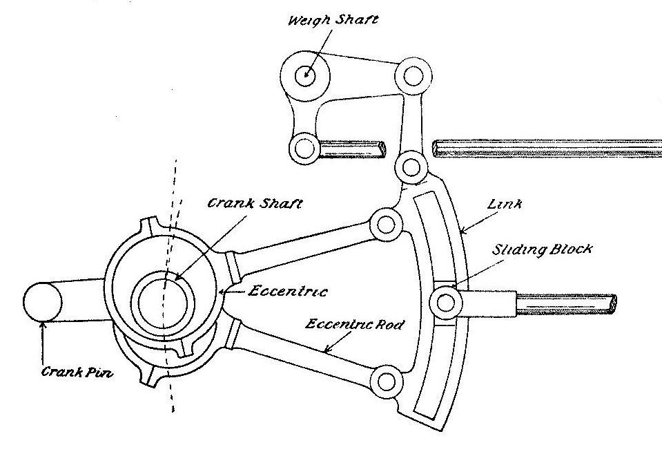 Wilf |
|
uuu
Elder Statesman
your message here...
Posts: 2,808
|
Post by uuu on Feb 17, 2024 21:14:17 GMT
Your new friends as the club are likely to have some ideas.
Me: I'd try making some studs out of slightly oversize rod, cut with a split die that's been stretched right out - see if it fits better.
Wilf
|
|

