|
|
Post by builder01 on Jun 18, 2020 21:27:42 GMT
I wonder why this was posted in the general chat for Simplex??
|
|
|
|
Post by builder01 on Jun 18, 2020 21:14:43 GMT
You are welcome! Yes, I often grind the end of a tap to create a better "bottoming" tap! The bolt pattern on the steam chest will end up being not exactly symmetrical. This is okay as it is the only way to avoid the valve spindle. The steam passages should be far enough away from the bottom of the bolts to not be a problem.
|
|
|
|
Post by builder01 on Jun 18, 2020 20:47:34 GMT
On both the drawings for the Simplex and the Super Simplex, it looks like the steam passages are not on the center line on the cylinder. This is because the drawing is drawn poorly. The center line of the cylinder bore is 1-5/8" from the reference side of the casting, which is the side that bolts to the frame. The center line of the port face is also 1-5/8" from the reference side. The steam passages should be machined equally on each side of the center line. The drawing makes it look offset from the cylinder bore, but, it is not. The bolt hole pattern in the cylinder end is really a 13 hole pattern with the top hole not drilled because it is on center line with the bore and the steam passages. The bottom hole of the pattern should be exactly on center. The valve spindle is offset from the cylinder bore by 7/16". The offset for the valve spindle groove in the slide valve is also 7/16". If you machine the port face and the slide valve exactly like the drawing they will be in perfect alignment. DO NOT SCALE the drawing, just use the written dimensions and the cylinder, steam chest and slide valve will align perfectly. One thing not to do, is to use the bolt pattern for the steam chest. One of the bolts will be exactly in line with the valve spindle! This bolt should be move toward the frame, or reference side, to just clear the valve spindle. If you drill the steam passages close to the cylinder bore, there is still plenty of material for bolts for the steam chest to screw into. The bolts will not collide with the steam passages, just don't drill them deep enough to break through. There is plenty of material for the bolts to screw into. The cylinder bores should also be reduced to 1-3/8". This will still give you plenty of power and the boiler will be able to more easily keep up with the demand of the cylinders. At 1-3/8" bore, this is a very powerful locomotive. This also puts the steam passages farther away from the port face which gives you more material for the steam chest bolts. Here's a few photos of my Super Simplex cylinder. These are the same exact castings and machine work for the Simplex.  DSCN0811 DSCN0811 by Builder16, on Flickr  DSCN0923 DSCN0923 by Builder16, on Flickr  DSCN1007 - cropped DSCN1007 - cropped by Builder16, on Flickr |
|
|
|
Post by builder01 on Jun 5, 2020 22:13:37 GMT
My Super Simmplex weighs about 125 pounds. I made the running boards a little thicker at 3/32" versus 1/16". I also used 1/16" brass for the water tanks and all of the plate work for the cab. You need as much weight as possible, especially at the back of the loco, as it is a bit front heavy.
As for the motion plates, they are mounted even with the tops of the frames. (unless you get the laser cut plates, which are not made quite right). The expansion link brackets are mounted to the motion plates by using the 3/16" hole and a bar going through the brackets to locate the entire assembly on the frame. As you can see on the print, there is no dimension for exactly where the motion plates mount, or, where the expansion link brackets mount to the motion plates. The 3/16" hole and a bar going through it, locates everything correctly. And, yes, this little bit of information is not in the Super Simplex text, only in the Simplex text.
It is good to have the complete text from both build threads, as there is information in each that is not in the other. Not a problem for an experienced builder, but, for a person like me, I needed all the help I could get!
I always encourage a builder to go with the Super Simplex design as it has fewer errors than the regular Simplex. Some folks are just stuck on building the old Simplex design no matter what.
David
|
|
|
|
Post by builder01 on Jun 3, 2020 9:37:39 GMT
Ken, check your regular email. I sent you everything you need.
|
|
|
|
Post by builder01 on May 23, 2020 19:49:56 GMT
Hi Steve, Thank goodness Don Ashton supplied me with a complete stick diagram of the valve gear with all of the relevent dimensions. I'm staggered that there are published designs where this basic information is missing. I just made everything to the drawing. The only adjustment on mine is the position of the bobbin. By making everything to the drawing, I assume you mean to Don's specifation, not the original drawing. What is particularly interesting, is that despite all of the shortcomings of the drawings, and lack of CAD and valve simulators, people have managed to create working miniature steam locomotives from poorly made drawings. Perhaps they were not built in an optimal way, but, they worked well enough to provide the builders and riders with much entertainment. There are, of course, no "perfectly built" miniature locomotives, but, neither were the full size. The drawings for my loco were done in 1989, I was sure there were going to be problems, but, as many had already been sucessfully built, I was not worried that there was not anything I could not overcome. |
|
|
|
Post by builder01 on May 23, 2020 15:56:11 GMT
Busy changing the reversing lever. I don't like the screw type and want to use a lever type but I am having problems not getting enough travel  Assy with Valvegear D Assy with Valvegear D by Kenneth Lindeman, on Flickr The screw type reverser allows for about 1-7/16" movement of the valve gear reach rod, of which you only need about 1-1/4" to change from full forward to full reverse. I used a spacer on the reverser screw to limit the travel in each direction, you don't want the die block to bottom out in the expansion link. If built for 7-1/4" gauge, the full movement of the reach rod would be about 1.915", of which you would need about 1.666" to go from full forward to full reverse. If your quadrant does not allow for this much movement, perhaps the quadrant needs to be larger? These numbers are for the Super Simplex. The Simplex allows for even more movement of the reach rod at 1-11/16". I see you have the reverser stand on the inside of the frame, this will probably cause the reach rod to collide with the boiler. David |
|
|
|
Post by builder01 on May 23, 2020 13:50:55 GMT
Roger If you have not been given the PCD, how do you calculate it and what dimensions do you need? Ron You are venturing into complicated territory here. The eccentricity of the return crank pin is the amount that the expansion link will swing back and forth. (They are connected by the eccentric rod). The designer of the valve gear will design the gear using a number of assumptions - one of which is how much angular swing they want impart to the expansion link. They don't always tell you what this is! What you are normally told is how long the return crank is from crank pin to return crank pin centres. Then the normal way of setting is to achieve the effect that Julian described, and others have alluded to. First, construct an adjustable eccentric rod, and fit the return crank in approximately the right position. Then set the crank on FDC or BDC (exactly) and adjust the eccentric rod until moving the reverser from full forward to full reverse doesn't move the valve rod. Then move from FDC to BDC (or vice versa) and see if the valve rod still doesn't move. If it does, lengthen or shorten the adjustable eccentric rod, and re-position the return crank to try and achieve no movement. Keep doing this until success is achieved, and then fix the return crank permanently, and make the final eccentric rod using the centres from your adjustable one. Then do it all over again on the other side of the engine! This is exacly how I did it for my Super Simplex. Evans gave no PCD for the return crank. No CAD or valve simulator, just adjust the rod length and return crank until it is correct. |
|
|
|
Post by builder01 on May 1, 2020 12:34:19 GMT
Hey Pete, photo posted just fine! Thank you. Which holes need to be closer, the holes in the rod? A method I used to set the distance, was to measure the distance between the axles. This should be the same distance between the holes on the rod. Does not matter what the drawing shows, the holes in rod must match the axle centers. I measured over the axles with them pushed together and another measurement over the axles with them pushed apart. You may have to get someone to manipulate the axles while you manipulate your caliper. The average of these two measurements is the center distance between the axles. (minus the diameter of one axle!) This is also the number for the distance between the holes in the rod. I assume you have a mill to accurately position the holes. Drill and ream one hole, turn the hand wheel the distance you have for the axle centers and drill and ream the other hole. No, you were right about the average... I use this method for finding the centres of any feature. It works even if the hole or axle sizes are different. Oh yes, if it is the averaage, the measurement over the axle diameter is taken into consideration as the other measurement is taken between the axles. Thanks Roger!! At any rate, the wheels on my 0-6-0 all went round and round the first time with no binding. |
|
|
|
Juliet
May 1, 2020 0:11:15 GMT
Post by builder01 on May 1, 2020 0:11:15 GMT
Hey Pete, photo posted just fine! Thank you. Which holes need to be closer, the holes in the rod?
A method I used to set the distance, was to measure the distance between the axles. This should be the same distance between the holes on the rod. Does not matter what the drawing shows, the holes in rod must match the axle centers.
I measured over the axles with them pushed together and another measurement over the axles with them pushed apart. You may have to get someone to manipulate the axles while you manipulate your caliper. The average of these two measurements is the center distance between the axles. (minus the diameter of one axle!) This is also the number for the distance between the holes in the rod. I assume you have a mill to accurately position the holes. Drill and ream one hole, turn the hand wheel the distance you have for the axle centers and drill and ream the other hole.
|
|
|
|
Post by builder01 on Apr 27, 2020 18:20:55 GMT
Okay, thank you!
|
|
|
|
Post by builder01 on Apr 27, 2020 12:16:36 GMT
As the year has turned the focus of the project has shifted towards manufacture of tender spring gear and other small parts, this is where we need you! Volunteers are the lifeblood of projects like this and several small homework projects are available if anyone wishes to make components and assist Where can drawings be found? |
|
|
|
Juliet
Apr 22, 2020 18:47:17 GMT
Post by builder01 on Apr 22, 2020 18:47:17 GMT
I am a Facebook user, link is broken for me too.
|
|
|
|
Post by builder01 on Apr 21, 2020 11:14:32 GMT
The bench that the stand is attached to is on wheels. So it is not a problem to move around. I am not sure why I would want to lift the whole thing with a crane. At any rate, the stands can be raised and lowered enough that everything can be rotated and everything is accessable. Currently, the raising mechanisms have been removed from the rolling bench and have been attached to their own wooden bases. I can take them to my club track or anywhere to lift the locomotive even when it's sitting on track.
|
|
|
|
Post by builder01 on Apr 20, 2020 18:08:49 GMT
7-1/4" scale? That will be pretty big, (I think you mean 7-1/4" gauge). At any rate, good work! Your drawing looks fine!
|
|
|
|
Post by builder01 on Apr 20, 2020 12:33:10 GMT
|
|
|
|
Post by builder01 on Apr 20, 2020 12:12:49 GMT
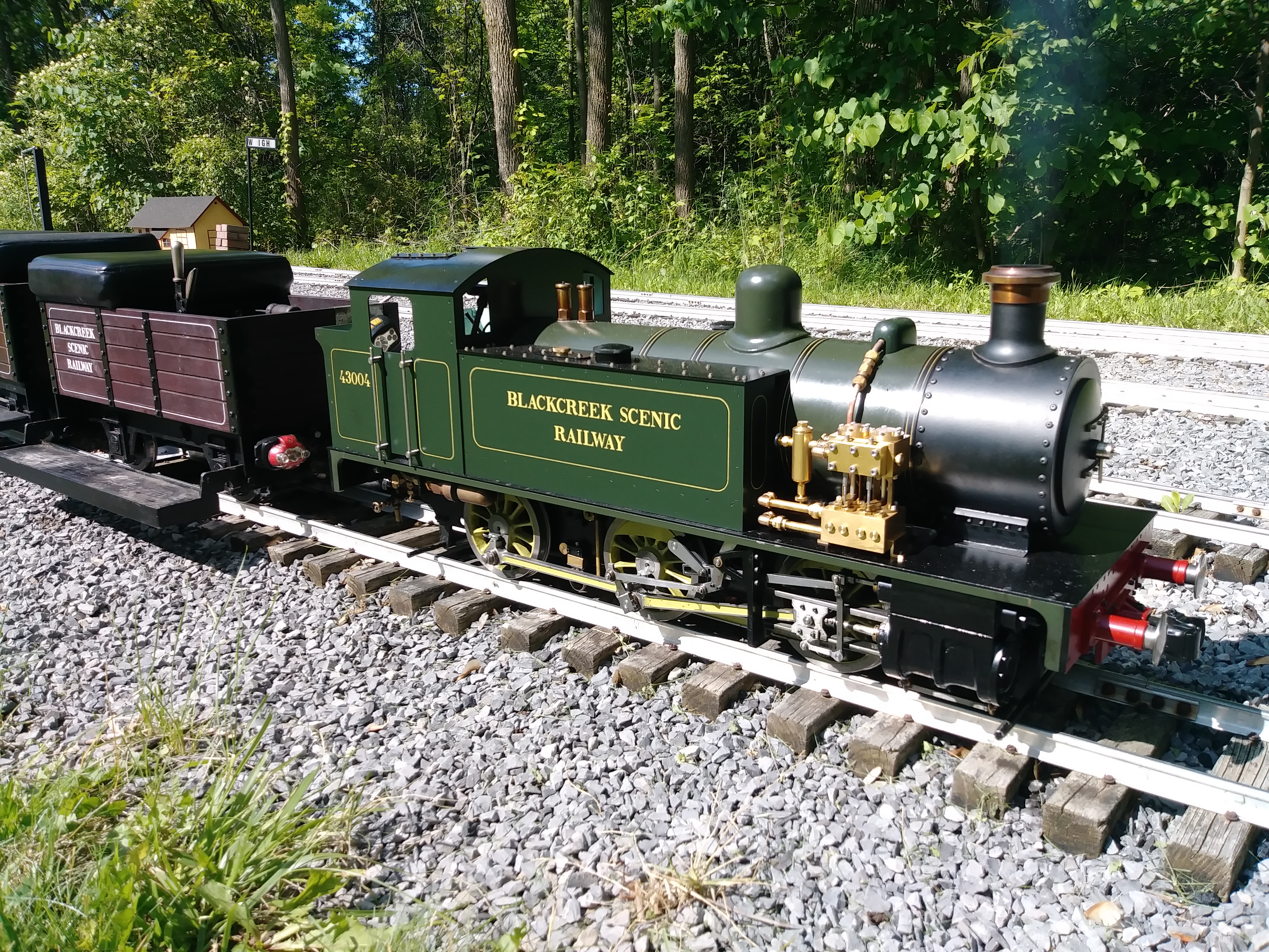
Hi John, I have a website dedicated to the Super Simplex. It is mostly the same as the Simplex, with a few upgrade changes. But most things apply to both locomotives. If you need the build articles, which are exactly the same as what is in the book, PM me and I can gelp you out. Here's the URL for my Super Simplex website; supersimplex.yolasite.com/The Simplex is a great running locomotive. It is lots of fun to drive and has plenty of power, even with reduced cylinders. I reduced mine to 1-3/8" diameter. It makes it run more efficiently as suggested by a friend. There are many little things I changed to make it more friendly to operate and maintain. ![]()  20190621_162915 20190621_162915 by Builder16, on Flickr |
|
|
|
Post by builder01 on Mar 27, 2020 21:47:01 GMT
I use Flickr also. I bet the parts Pete made are something like this. Photos are such an important part of online forums, especially if you are making something. If you don't know how to do it, take the time to learn. We will all benefit from your effort.
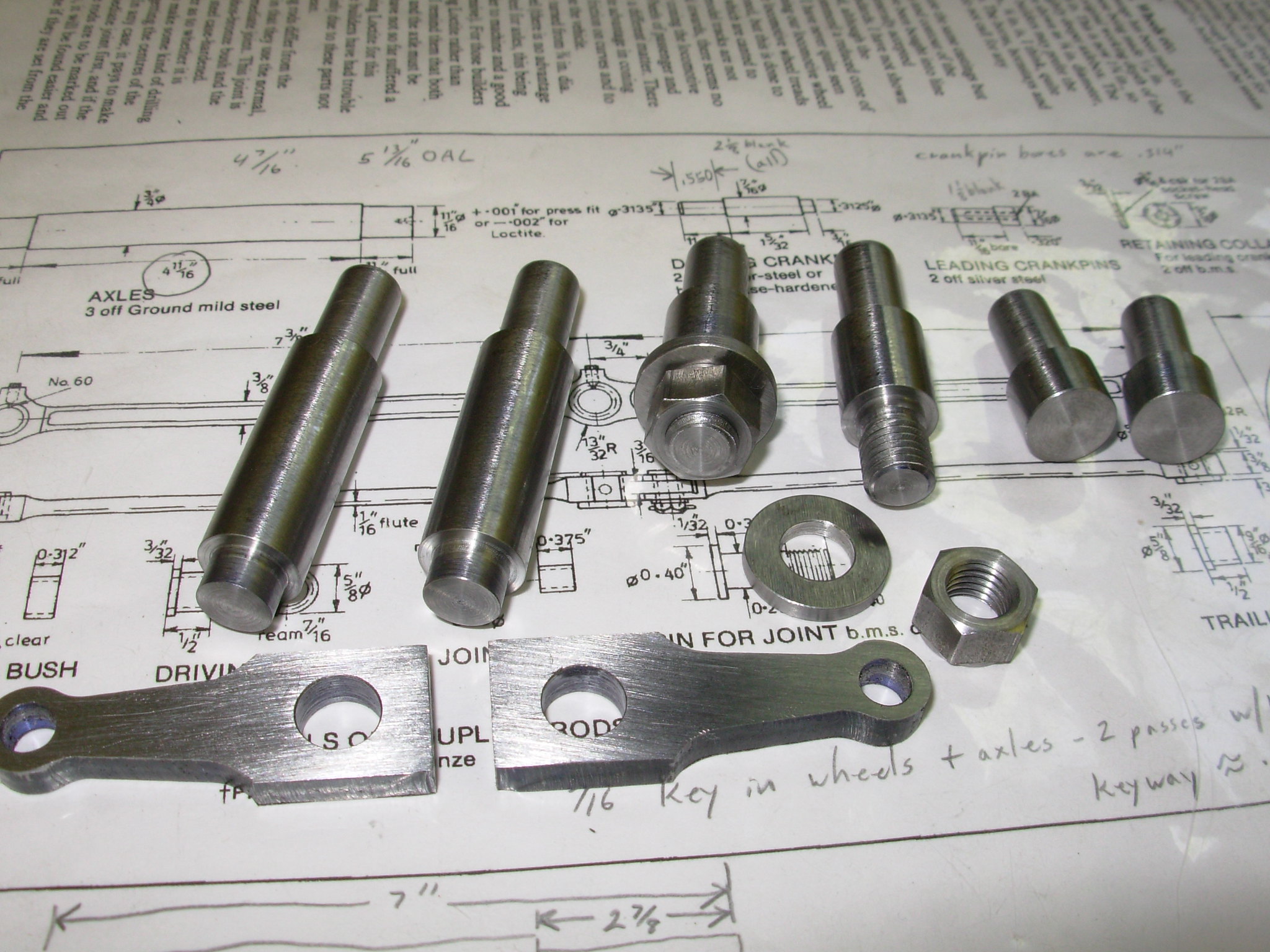
DSCN0749 by Builder16, on Flickr David |
|
|
|
Post by builder01 on Feb 8, 2020 14:16:42 GMT
|
|
|
|
Post by builder01 on Nov 10, 2019 14:16:42 GMT
|
|