rrmrd66
Part of the e-furniture

Posts: 339 
|
Post by rrmrd66 on Mar 27, 2018 6:44:19 GMT
Hi Malcolm, Great “how to” & lovely work to boot! Cheers Kerrin Thanks Kerrin. I need all the motivation I can get. regards Malcolm PS Take it easy with our cricketers please. It's bad enough with having the All Balcks! |
|
rrmrd66
Part of the e-furniture
Posts: 339
|
Post by rrmrd66 on Mar 26, 2018 17:25:34 GMT
Evening everybody As promised here is the second half of the con/coupling rod saga. COUPLING RODS The first photo is a repeat of the one posted yesterday in the connecting rod part. However, we are interested this time in the four pairs of PBz pieces in the left hand column. These, Don Young recommends, are to be tinned and soldered together to ensure that after boring to 3/8" diameter they will be "perfect halves" when " broken" apart again. Being new to all this it sounded a bit drastic. However all went well and I was able to proceed to the milling machine. 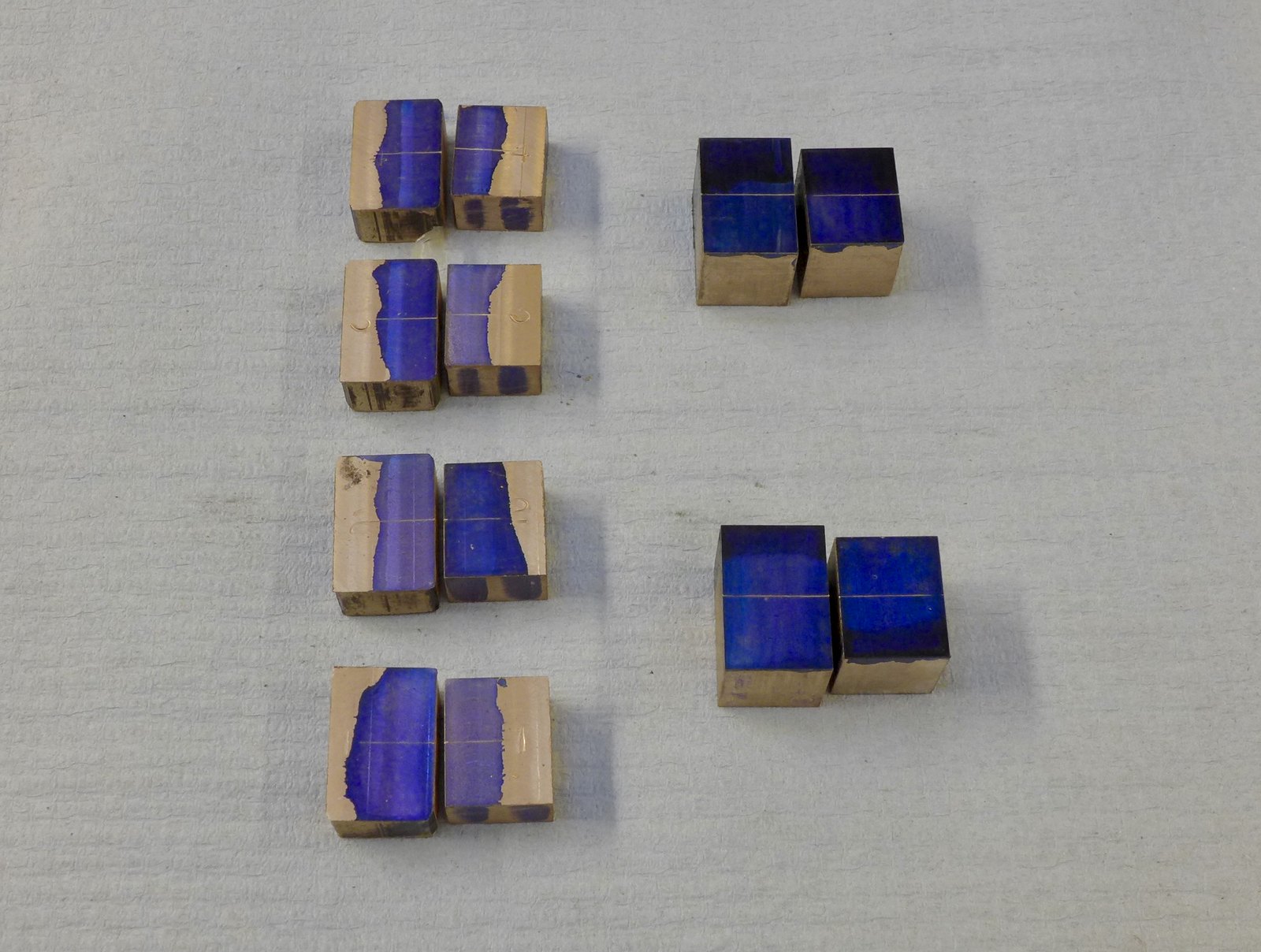 fullsizeoutput_68b fullsizeoutput_68b by Malcolm HARWOOD, on Flickr The "brasses" are still joined here and are having the locating slots milled. The soldering together also guarantees that the thickness of the slot walls is the same. Note two partly finished brasses stood by the side of the vice. 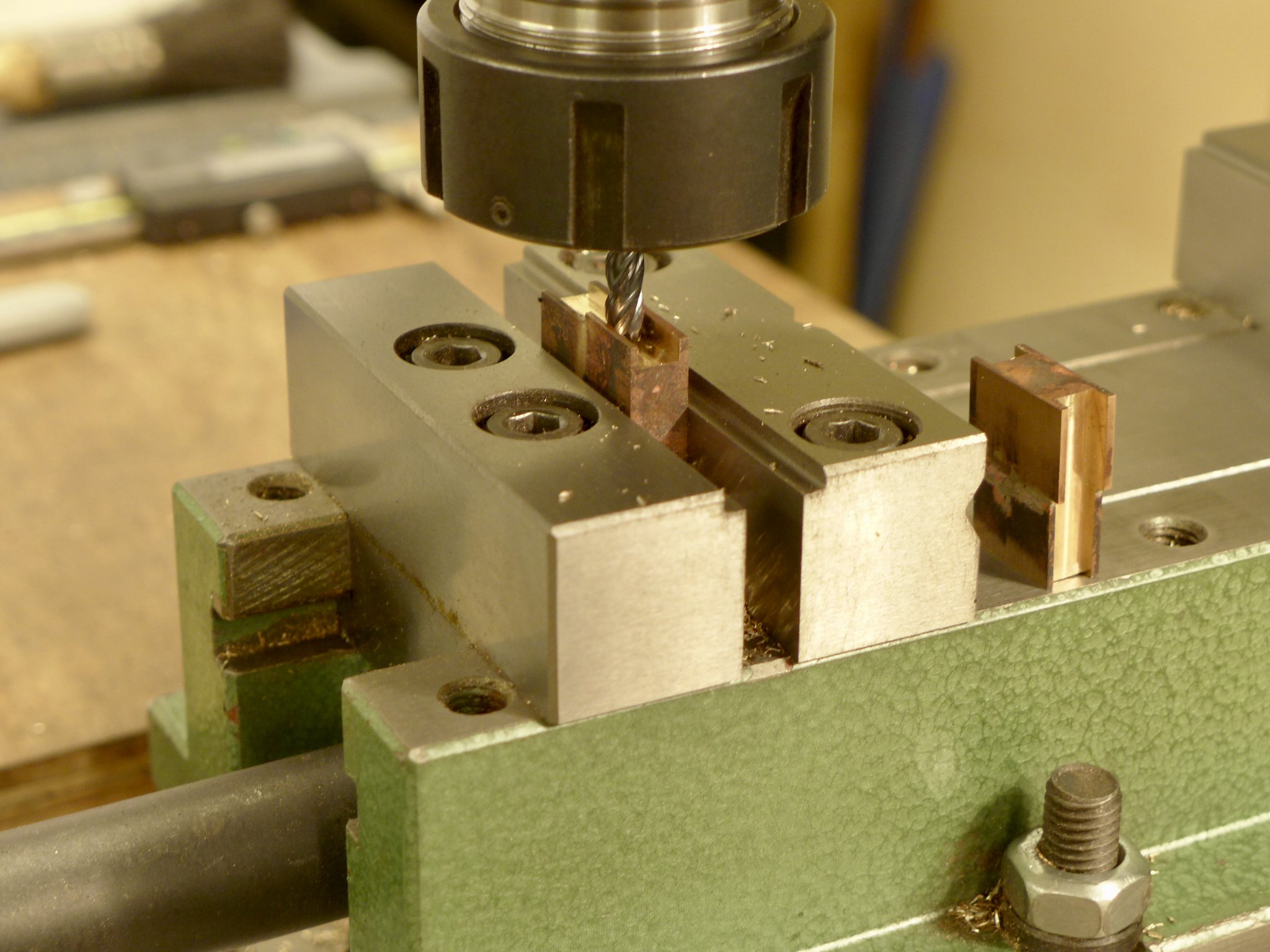 fullsizeoutput_690 fullsizeoutput_690 by Malcolm HARWOOD, on Flickr Next the 3/8" diameter bore was made by slowly opening the hole out ( note drills) and finishing with a hand reamer. Tip here. Make sure that the brass is held as I have shown. If you do it "longitudinally" you may break the soldered joint (like I did on the last one!)  fullsizeoutput_691 fullsizeoutput_691 by Malcolm HARWOOD, on Flickr Here are the bored out brasses awaiting fitting to the coupling rods. If you enjoy hand filing radii in small pieces of Phosphor bronze then you will love the next part. The "back lip", by the way has to be removed otherwise you cannot get the brass into the closed housing in the rod. Each brass has to have one semi circular 1/2" radius,and at the other end a lager radius of about 1.5", or so.  fullsizeoutput_693 fullsizeoutput_693 by Malcolm HARWOOD, on Flickr To ensure that the center distance of the coupling rod is to plan and equal to its partner DY suggested turning up two shouldered pins from scrap axle rod which you will fortuitously have left over after cutting the axles from a standard 12" length. 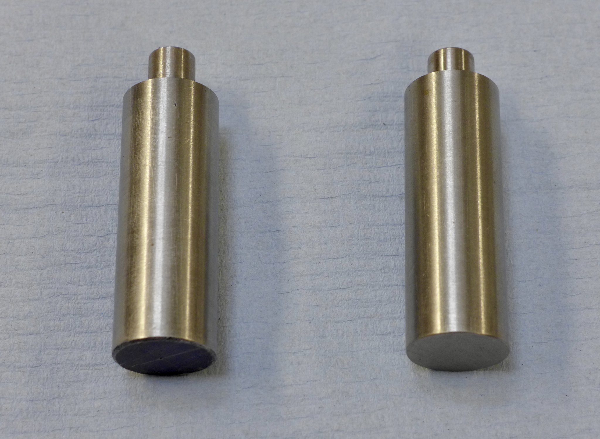 fullsizeoutput_69d fullsizeoutput_69d by Malcolm HARWOOD, on Flickr These are then placed in the horn blocks clamped to their stays. (Please excuse rusty old spare clamps which are very useful in the silver soldering department) Here you can see I have one fitted and am gently coaxing the left hand end to fit. Fortunately, not as difficult as I first thought. 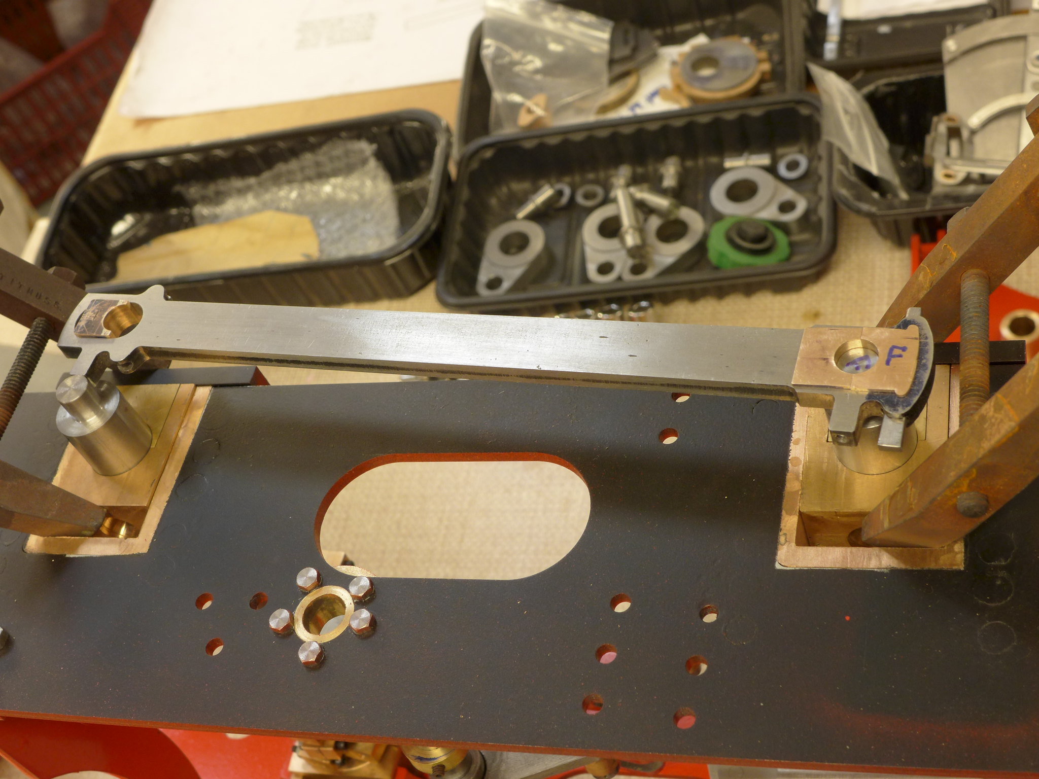 P1010250 P1010250 by Malcolm HARWOOD, on Flickr And here we are. Both finished coupling rods. One assembled and one in "exploded form" complete with cotter pins. 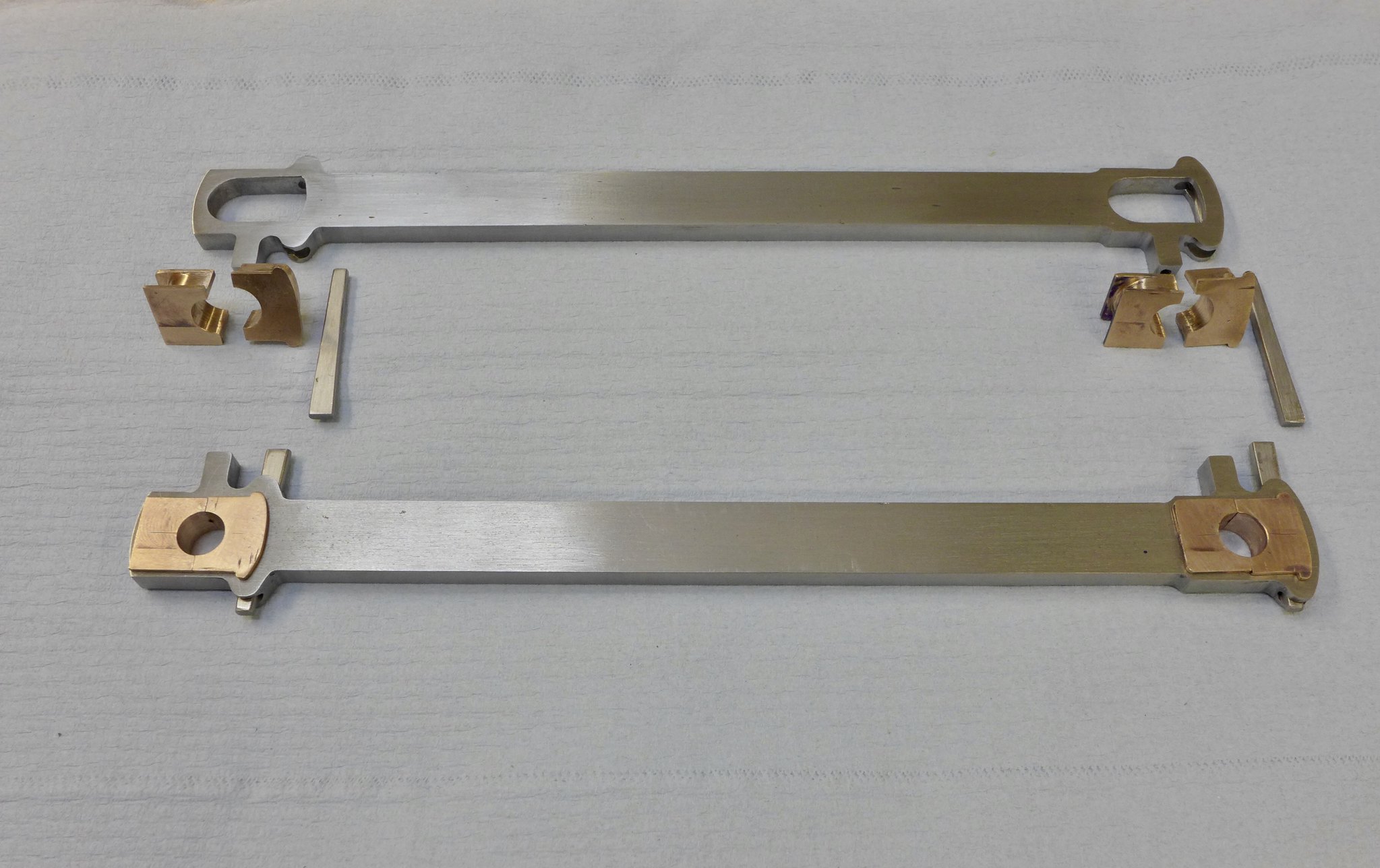 fullsizeoutput_69b fullsizeoutput_69b by Malcolm HARWOOD, on Flickr That's enough for now. Next up are the crosshead fabrications. However I am working inexorably towards the cylinders and valve chests. Yikes! Then the fun will begin. Thanks for reading. Cheers Malcolm |
|
rrmrd66
Part of the e-furniture
Posts: 339
|
Post by rrmrd66 on Mar 26, 2018 9:46:50 GMT
My locomotive builder friends and I need to build a stand by which we can rotate a locomotive to work on the innards underneath as you do occasionally. We have a few requirements in that we do not want to build one each but we want to be able to loan it amongst ourselves in time of need and we also have a variety of locos, namely 5" ModelWorks Britannia, 5" Ashford, Achillies, 5" N.G Hunslet, P.V Baker and down to little Juliet plus others in between we can't remember at present or have hidden from the wife! Are there any good ideas out there that we should include in our design?? One thing I though is necessary is the ability to alter the spacing between the support to accommodate the different length of loco, naturally.Something that can be moved but then braced up to support the whole thing. Does it need braked wheels? Any photos and wisdon would be greatly appreciated. Hayden Hi Hayden Have a look at this about a third down the page: modeleng.proboards.com/thread/11844/hunslet-5-inch-gauge-build?page=5Cheers Malcolm |
|
rrmrd66
Part of the e-furniture
Posts: 339
|
Post by rrmrd66 on Mar 26, 2018 7:34:59 GMT
Good Morning Richard and Good Morning Julian
Yes good tip about the soft soldering.In my ignorance I used a small amount of silver solder wire on the fluxed faces, allowed to cool, re-fluxed, then clamped the faces together and reheated until "it looked right"!
The two halves soldered together gave me two matching halves of the 3/8" bore, when they were eventually separated. Worked quite well.
The last time I tinned metal with solder and a soldering iron the size of a house brick was when I found myself doing C&G Metal Work as am apprentice. JFK was still the USA president!
Super glue would have worked I am certain but had none to hand. I find double sided sellotape very helpful as well in this type of application.
Coupling rods write up to follow in next few days,then cross heads and, Julian, the cylinders.
Cheers
Malcolm
|
|
rrmrd66
Part of the e-furniture
Posts: 339
|
Post by rrmrd66 on Mar 25, 2018 20:01:03 GMT
Good Evening to you all. There appears to be uncertainty about the derivation of the phrase "the devil is in the detail". However, my suggestion is that is was first used by someone making connecting rod and coupling rod brasses. My last update at the beginning of February 3rd would suggest that I have been slacking and not putting the effort in. This is far from the truth. On average I have spent about 4 hours per day , 6 days per week making these parts. That is about 140 hours. Any way less whingeing and on with the build. So that you don't fall asleep with my ramblings I will split the update into two. First of all THE CONNECTING RODS. I left you last time saying that I would tell you all about machining the connecting rods to thickness. A simple matter of milling 1/16" off each side of the laser cut rods. Here in this picture you will see that I have already made a jig to hold the rod firm whilst milling it. When the first side was finished I turned it over and commenced on the second side only to encounter heavy vibration. This was so bad that I could not get a good finish and manged to blunt the HSS end mill. Packing the under side up with 1/16" plate and clamping it with a heavy duty strap, that you will see behind the rod, allowed me to mill it in "two bites', by moving the clamp as the cutting progressed. Just a note of caution to other beginners, like me. The Don Young design called for 3/8" thick MS bar. The laser cut rods from Model Engineers Laser were delivered in 10mm thick bar. Easy when you know, but had me baffled for quite some time. Maybe the supplier could put on the invoice, or on his web site, that this is so? 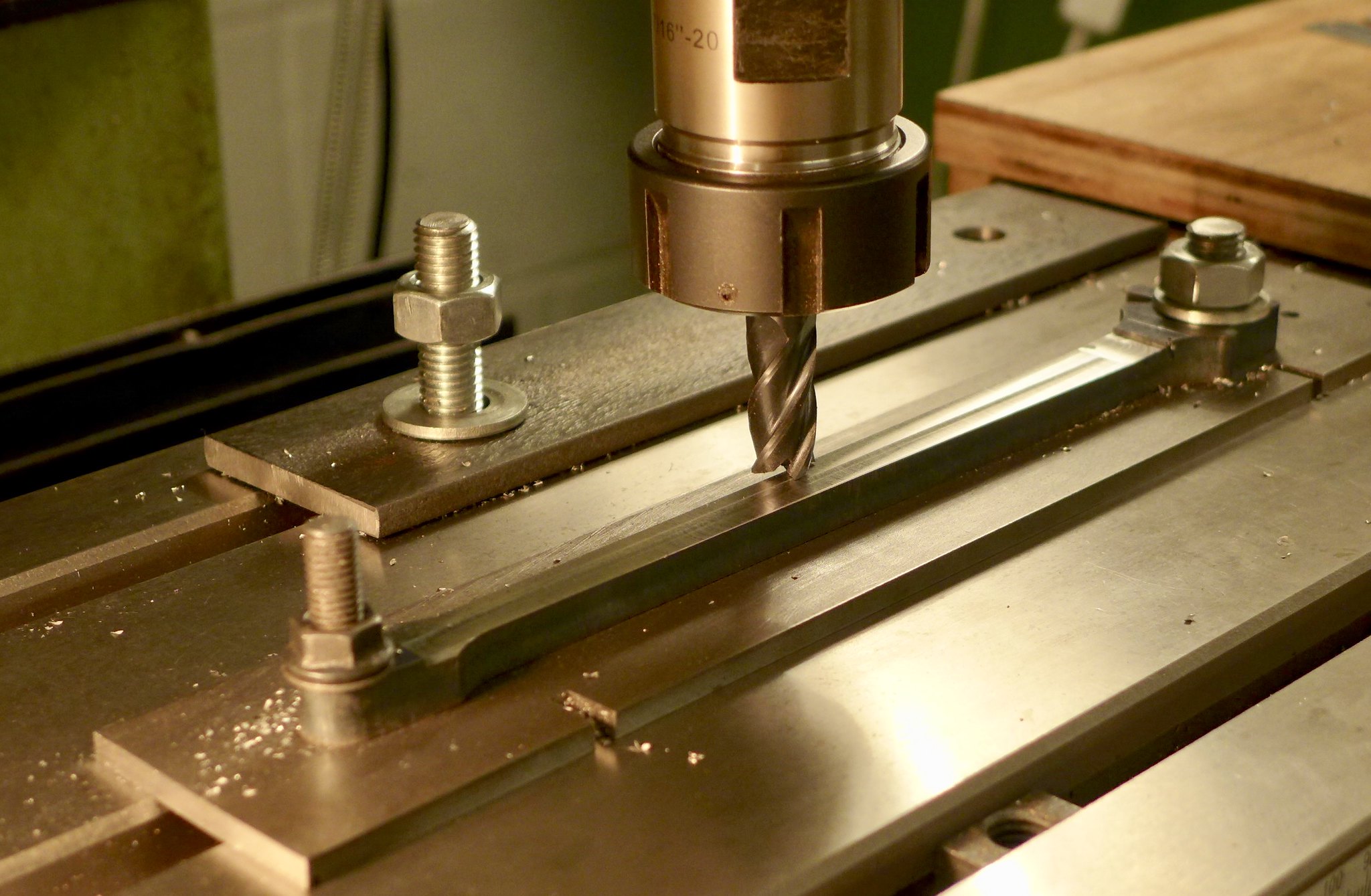 fullsizeoutput_688 fullsizeoutput_688 by Malcolm HARWOOD, on Flickr Next came the brasses. Here you see the milled up blanks, to size, prior to tinning and silver soldering together so that they could be bored as two exact halves. Here again I was dubious as to my ability to be able to do this as silver soldering is a bit of a black art to me, although I must say the more you do it does seem to get easier/better. This picture shows both coupling rod brasses (left hand) and connecting rod brasses (big end) on the right. fullsizeoutput_68b by Malcolm HARWOOD, on Flickr The "little end" of the connecting rod has one half round bush, the other half being adjustable onto the gudgeon pin in the crosshead by a small sliding wedge and 6BA screw arrangement. (See last picture.) This photo shows the milling of the 15deg. wedge on a nice adjustable angle plate (an extra gift from the friend who gave me his Harrison lathe...thank you Peter) which i set with a digital protractor. You will doubtless recognize the Myford milling vice, which fitted nicely.  fullsizeoutput_68a fullsizeoutput_68a by Malcolm HARWOOD, on Flickr Finally after many hours of hand filing I have them finished. I have everything numbered so that all four rods and their bearings are each a set. 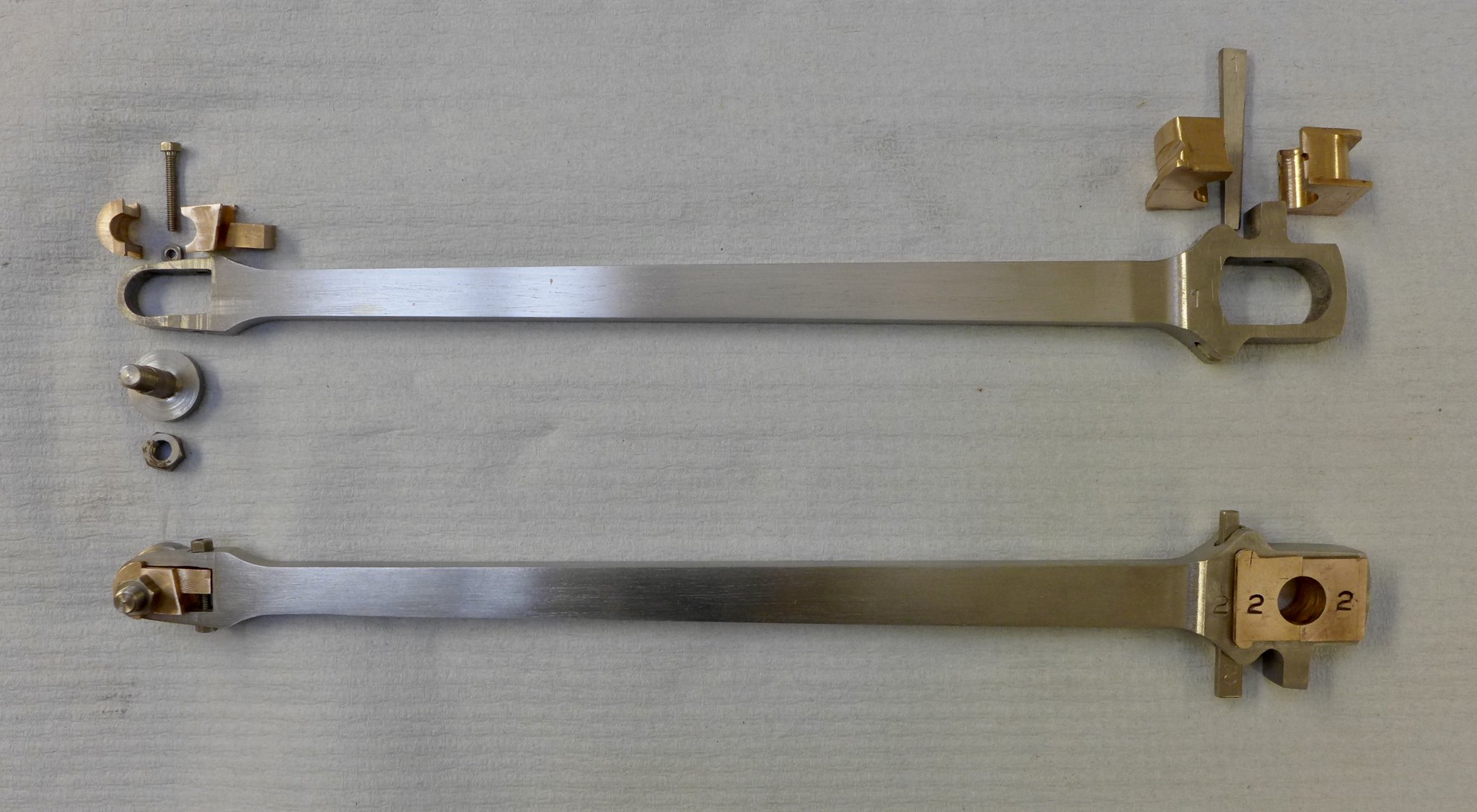 fullsizeoutput_69f fullsizeoutput_69f by Malcolm HARWOOD, on Flickr it only remains for me to prime and paint them. I noticed that all the Hunslets on the Lake Bala Railway, which I visited last October, have painted rods and I will do the same. I will do another post on the coupling rods. Thanks for reading. I do hope this is of interest to a few of you? Cheers Malcolm |
|
rrmrd66
Part of the e-furniture
Posts: 339
|
Post by rrmrd66 on Mar 10, 2018 17:50:46 GMT
Hi Joan Thanks for this. Most interesting. I hope that one of our more knowledgeable UK forum members will add something to this " biggest UK engine" discussion, as I am a relative newcomer to all of this. In the meantime you might enjoy reading this: www.p2steam.com/Cheers Malcolm |
|
rrmrd66
Part of the e-furniture
Posts: 339
|
Post by rrmrd66 on Mar 10, 2018 7:36:11 GMT
Hi Malcom, Several years ago I went to the UK for a trip from London to Darlington with the Tornado locomotive leading the train. I really enjoyed the day. Something that surprised me was the reduced size of the locomotive. The locomotive initially appeared as almost deceiving, it seemed to me unrealistically small, almost like a toy or taken from an amusement park. Before that day, I had not realised that British steam locomotives were so small compared with European ones. But of course, then she was able to pull a significantly long and possibly heavy train at amazing speeds, which I have never experienced on a steam train elsewhere. This made me fully appreciate and understand what British steam locomotives were all about, and all the pride they receive in the UK. Joan. Hi Joan I'm no expert on this, but don't you have different (wider) track gauges in Spain? This would give the impression of a larger engines, would it not? Have you visited the National Railway Museum at York? When you stand by the side of the mainline express engines (at track level) they seem anything but small. Cheers Malcolm |
|
rrmrd66
Part of the e-furniture
Posts: 339
|
Post by rrmrd66 on Mar 9, 2018 20:00:10 GMT
Hi mr swarf See last years thread "How ridiculous is this" in this section. 50PCS 1/1.5/2/2.5/3mm HSS Titanium Coated High Speed Steel Cost £2.51 about 5p each They are OK. I have been using them. If they get blunt or you break one throw it away. Get on with building that engine?? Cheers Malcolm  |
|
rrmrd66
Part of the e-furniture
Posts: 339
|
Post by rrmrd66 on Mar 8, 2018 16:12:00 GMT
Well yesterday, truth be told. A special charter on the North York's Moors Railway for all those involved with Tornado, organised by the A1 Trust in Darlington (I am a volunteer on the P2 Prince of Wales build and a Mikado Club member) Great to see it rolling past you just feet away at Grosmont. Onto Pickering and back just as the light went and the temperature dropped like a stone. 3" of snow this morning but its nearly all gone now. Cheers Malcolm  fullsizeoutput_68f fullsizeoutput_68f by Malcolm HARWOOD, on Flickr |
|
rrmrd66
Part of the e-furniture
Posts: 339
|
Post by rrmrd66 on Mar 6, 2018 16:26:36 GMT
|
|
rrmrd66
Part of the e-furniture
Posts: 339
|
Post by rrmrd66 on Mar 2, 2018 8:10:18 GMT
Suddenly steam engines everywhere!
BBC4 From Ice to Fire Thursday 1st March 9pm, but get it on catch up.
Braveheart on the Dartmouth Railway (I think?). Experts please expand on this.
Dr. Helen Czerski shoveling coal and explaining the physics of heat energy.
Worth a watch?
Cheers
Malcolm
|
|
rrmrd66
Part of the e-furniture
Posts: 339
|
Post by rrmrd66 on Feb 16, 2018 10:09:40 GMT
Morning everybody. I think we have flogged this one to death. Well, until the next time! All commercial seal manufacturers employ copious amounts of smoke and mirrors where claims of their ptfe based compounds are made. Caveat emptor. Perhaps, if you have time, you might like to read the attached from the originators themselves, DuPont. It goes into a lot of detail about the properties of the material and the addition of fillers. www.rjchase.com/ptfe_handbook.pdfBack to the Hunslet! Cheers Malcolm |
|
rrmrd66
Part of the e-furniture
Posts: 339
|
Post by rrmrd66 on Feb 14, 2018 20:29:19 GMT
Half term up here. Took the two granddaughters (7 and 9) to the NRM York today to see Tim Peake's reentry capsule.
Grandfather a bit underwhelmed, but the girls thought it "good".
Of more concern, to me at least, is the report in the press of the reorganization of the stores and workshop space into a "wonder-lab" interactive space for children to interest them in science and technology.
Really?
After laying waste apparently to the Photographic Museum at Bradford the curatorial mafia of London's Science Museum Group are now wanting to modernise the NRM and bring it "up to date".
My two were more fascinated by looking down into the workshop at a volunteer engineer hand grinding some piece of Sir Nigel Gresley prior to welding ( the sparks were the draw) and another guy reaming out part of a super heater. Actually seeing men and machinery will have more of a lasting impression upon them than any amount of hands on button pressing I'm certain.
They also enjoyed wandering around the stores discovering all sorts of strange things on the shelves in glass cases.
The Gresley Society had a small stand there manned by two volunteers one of whom did not sound over optimistic about the future of the workshop, the machine tools and future home of the part refurbished Pacific A4 60007 Sir Nigel Gresley.
After the trails and tribulations of the Flying Scotsman refurbishment are they going to repeat the past again?
Please tell me I have this all wrong and it will be OK.
Cheers
Malcolm
|
|
rrmrd66
Part of the e-furniture
Posts: 339
|
Post by rrmrd66 on Feb 13, 2018 16:50:21 GMT
Hi Roger
You wrote
"This is my solution for using PTFE for piston rings. Originally I was going to peg them like I did for the piston valves, but thought they probably wouldn't rotate in the bores so I didn't bother."
Yes you are right as long as the rings do not rotate and the gaps meet and create a leak path.
In the back of my mind is something from the past in that it is not good practice to have two o rings on the inside of the piston head as you can get pressure build up caused by the pumping action of the piston and subsequent damage to the static seals.
Maybe not a concern at our relatively low pressures?
Hello Wilf.
It is almost certainly due to the fact that the wall of the piston ring groove and its clearance to the piston ring is an integral part of the seal system. Hence if you try to put two rings in one groove this would not be the case.
I stand to be corrected by those who know more about this than me but isn't it standard practice with ic engines to only ever have one groove with one piston ring?
Cheers
Malcolm
|
|
rrmrd66
Part of the e-furniture
Posts: 339
|
Post by rrmrd66 on Feb 12, 2018 13:17:03 GMT
Hello Malcolm, Where did you source your Clupet rings? Or was it from the Clupet Piston Ring & Gage Co., in Maryport Cumbria? I ask as I am looking to source some metric rings. The Maryport source only appears to manufacture Imperial. Regards, Phil Hello Phil. I got them at the 2017 Midlands ME Exhibition from Live Steam Models trade stand. See: www.livesteammodels.co.uk/Got a funny feeling that they only do imperial sizes and that you have a long wait for anything non standard. Good luck Malcolm |
|
rrmrd66
Part of the e-furniture
Posts: 339
|
Post by rrmrd66 on Feb 12, 2018 9:15:38 GMT
Good Morning to you all.
Sorry to continue to bang on about this, but as you will have realised this is a subject I thought I knew a lot about but the deeper I dig I find I don't!
Eddie. Thanks very much for this information. Cast Iron piston rings (x2) in bronze pistons running in bronze bores can give long life. Exactly what I wanted to know.
Joan. Good point. I sometimes wonder why it is necessary to reinvent items. Unless I am mistaken you have highlighted what was always referred to as a "Shamban" seal, after the US manufacturer, but now part of the Trelleborg empire. All seal manufacturers do a similar style.
This type of seal is specifically made for the industrial light/medium duty hydraulic cylinder market and incidentally have been remarkably successful.
However, this specific seal needs a split piston design which I don't have.
Roger asks has anybody actually had long term success with this type of seal in a low pressure steam application? Any feed back on this?
I have already purchased two Clupet piston rings 1.625" dia.x 0.125" length x 0.0625 radial thickness (one spare, one to fit) and naturally I am keen to use them. They were £50+ the pair!
The original build articles from Don Young in LLAS are not particularly helpful although the drawings do refer to a gunmetal cylinders and pistons. The same applies to Reeves,from whom I purchased the castings in a job lot, although I seem to think they recommend a Viton O ring, which Pete (Doubletop) also recommends.
The piston casting is nominally 1.73" dia x 0.75" length
The finished size is 1.625" dia x 0.625" length
One seal groove is shown. Finished dimension: 0.25" length x 0.234 radial depth, thus I have sufficient room to fit two Clupet rings.
Thanks for reading
Cheers
Malcolm
|
|
rrmrd66
Part of the e-furniture
Posts: 339
|
Post by rrmrd66 on Feb 11, 2018 11:52:58 GMT
Hi Everybody
As I said above, "what do I know"?
Erikjan has actual good running experience with virgin ptfe with no filling material (which would certainly improve all mechanical properties). Roger is also going to use a ptfe based filled material.
Note that these designs rely on a "split" piston design. A "groove" type housing, like an O ring would use, would not allow a large radial cross section seal to be stretched in to the piston groove.
All my experience from industrial hydraulics says no. But at these very low pressures (6bar max?) the material is working well within its elastic limit (I guess) and so permanent deformation and extrusion is not an issue.
Would still appreciate one of the seasoned members advising me if my one piece gunmetal pistons and gunmetal cylinder bores with one clupert ring is a good or bad idea and why they say so.
Cheers
Malcolm
|
|
rrmrd66
Part of the e-furniture
Posts: 339
|
Post by rrmrd66 on Feb 10, 2018 11:50:55 GMT
Hi Roger
Can"t wait to see if it works under steam conditions.
BTW. Are there any engines that you know of that are running cast iron piston rings (1 5/8"" clupert) in gunmetal bores?
"Hard" journals work ok in "soft" bores. Why not hard piston rings in "soft" cylinders?
Any body else care to chip in?
Cheers
Malcolm
|
|
rrmrd66
Part of the e-furniture
Posts: 339
|
Post by rrmrd66 on Feb 10, 2018 8:35:41 GMT
Good Morning everybody.
Do you know the old saying about ask three experts a question and they will come up with three completely different answers.
And so it seems in Model steam engine engineering.
For 30+ years I worked in the hydraulic seal/mechanical engineering industry. For 25 years I was fortunate to be the MD of a company of 35 people, until retirement.
The seals were mainly of various elastomers, reinforced with appropriate fabrics, intended for use in high pressure (160-400bar) dynamic industrial hydraulics applications (steel, mining, earth moving machinery etc)
Our USP was that we looked closely at the application parameters (speed,pressure,temperature,hydraulic media,limits and fits and surface finish to name but a few).
We then recommended, in our experience, what would be best suited for that particular application. Normally with satisfactory results. If the factory did not have a suitable item we designed it and made it ourselves.
Amongst the product range of one of our suppliers was the product that from now on ladies and gentlemen you will please refer to as braided packing, not square rope!
Mainly a static sealing material for valve spindles etc but also used in dynamic applications, both rotary and reciprocating.
Indeed many of the NCB's mine hydraulic roof support three throw reciprocating ram pumps (with 95% water/5% oil hydraulic fluid) were sealed by braided packing sets in the most severe of applications (400bar pressure, mean rod speed of 15m/sec). Running times of 30000 hours were achieved. So we must have done something right.
Imagine my incredulity when I read that j1949 (first post in this thread) has achieved 20 years service from "twisted twine". Really? On a piston! Sealing steam!
My first thought would be impossible.
But there you are. What do I know?
Cheers
Malcolm
PS Roger. Your elegant design for your coaxial ptfe + O ring energised piston seal. I trust that the dynamic sealing ring, shown as a white material,is a modified "filled" ptfe and not virgin material.
But there again...............
|
|
rrmrd66
Part of the e-furniture
Posts: 339
|
Post by rrmrd66 on Feb 4, 2018 7:37:36 GMT
Hi Lisa
Great to hear from you.
Hope you are enjoying my first attempt at building a steam locomotive.
Surely though you can not be the only female in 5684 members??
regards
Malcolm
|
|


