rrmrd66
Part of the e-furniture

Posts: 339 
|
Post by rrmrd66 on Feb 3, 2018 14:00:25 GMT
Afternoon Chaps and Chappeses ( are there any female model engine builders by the way?) Progress report on the Hunslet build. This is a bit of a milestone for me . I had to have a trial fit of the eccentric valve gear, expansion link, die block weight shaft and reversing lever just to see if I was going in the right direction. Although a little stiff, it all appears to work OK. You will note the inside motion plate is ready to go on. However I cannot fit it to the frames yet. It locates in those three pairs of off set screw holes to the left the front axle, and it all has to line up with the valve chest spindle which is yet to be done, along with the cylinders. It would appear that there will have to be a little relieving carried out by the horn block casting. The laser cut motion plate has tabs to aid construction but they will be in the way after silver soldering and will have to filed off prior to final fitting. Still a big step forwards for me. 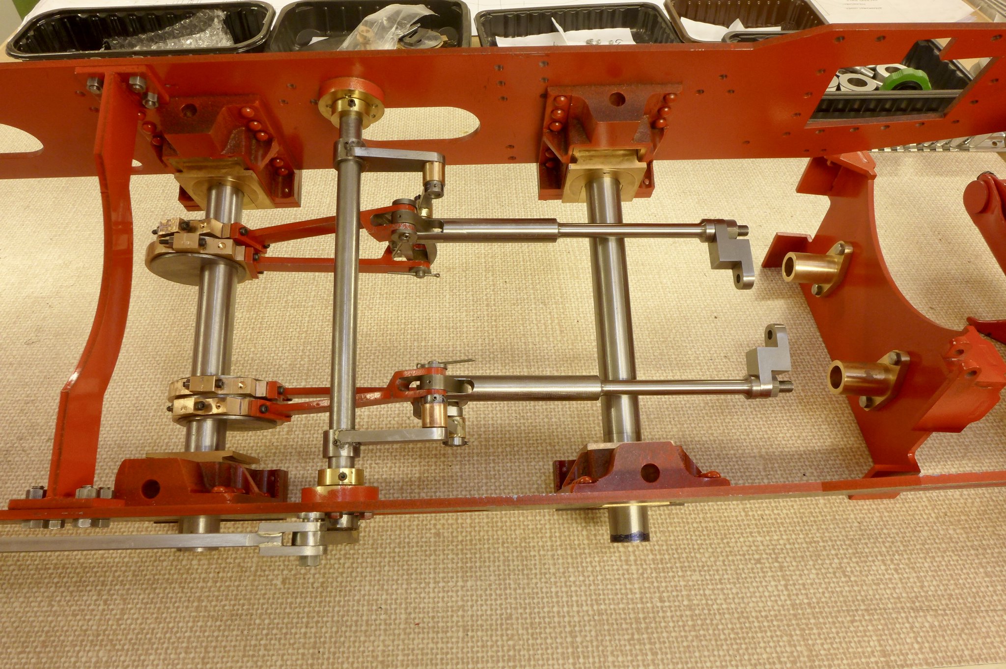 fullsizeoutput_67f fullsizeoutput_67f by Malcolm HARWOOD, on Flickr The pole reverser assembly is finished apart from closing the rivets and painting. I have been advised (by Julian, thanks BTW) not to cut the slots for the latch until I have the pistons mounted in the cylinders and I can then determine BDC and TDC, or whatever you guys call it. Locating holes for the tension spring are there and I have a spring ready to go on. The linkage for the cylinder drain cocks will have to come later. Probably a good idea not to finalise all the fixings until the very end. 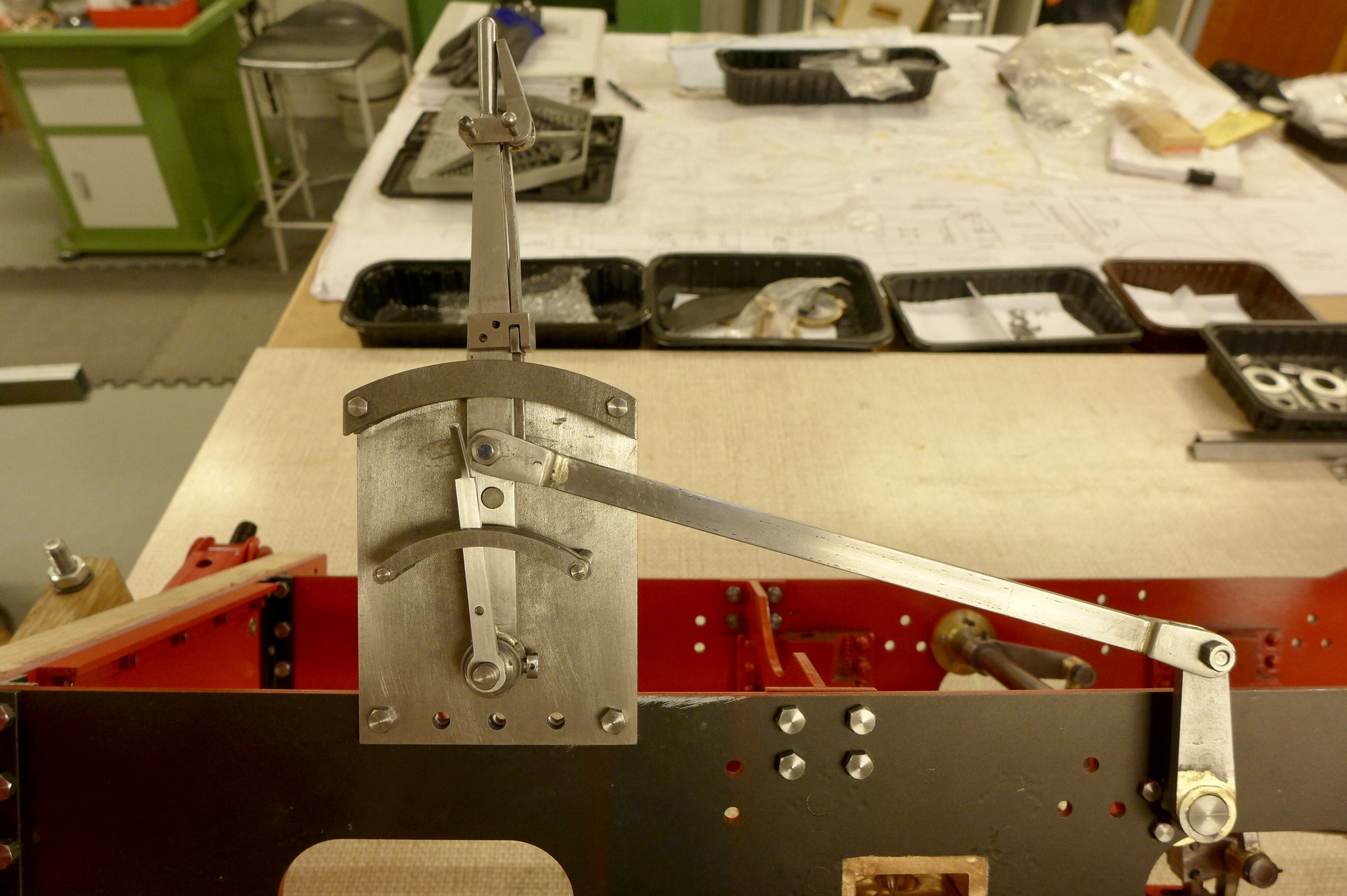 fullsizeoutput_680 fullsizeoutput_680 by Malcolm HARWOOD, on Flickr Moving on to the coupling rods you will see that I have sourced laser cut parts. This is very helpful in reducing construction time. However, there is always a down side and this manifests itself in the ugly cutting mark left by the laser. The localised heat gives a hard skin (reminds me of induction hardening) and also a slight taper across the face. What does everybody else do? Remove or ignore? 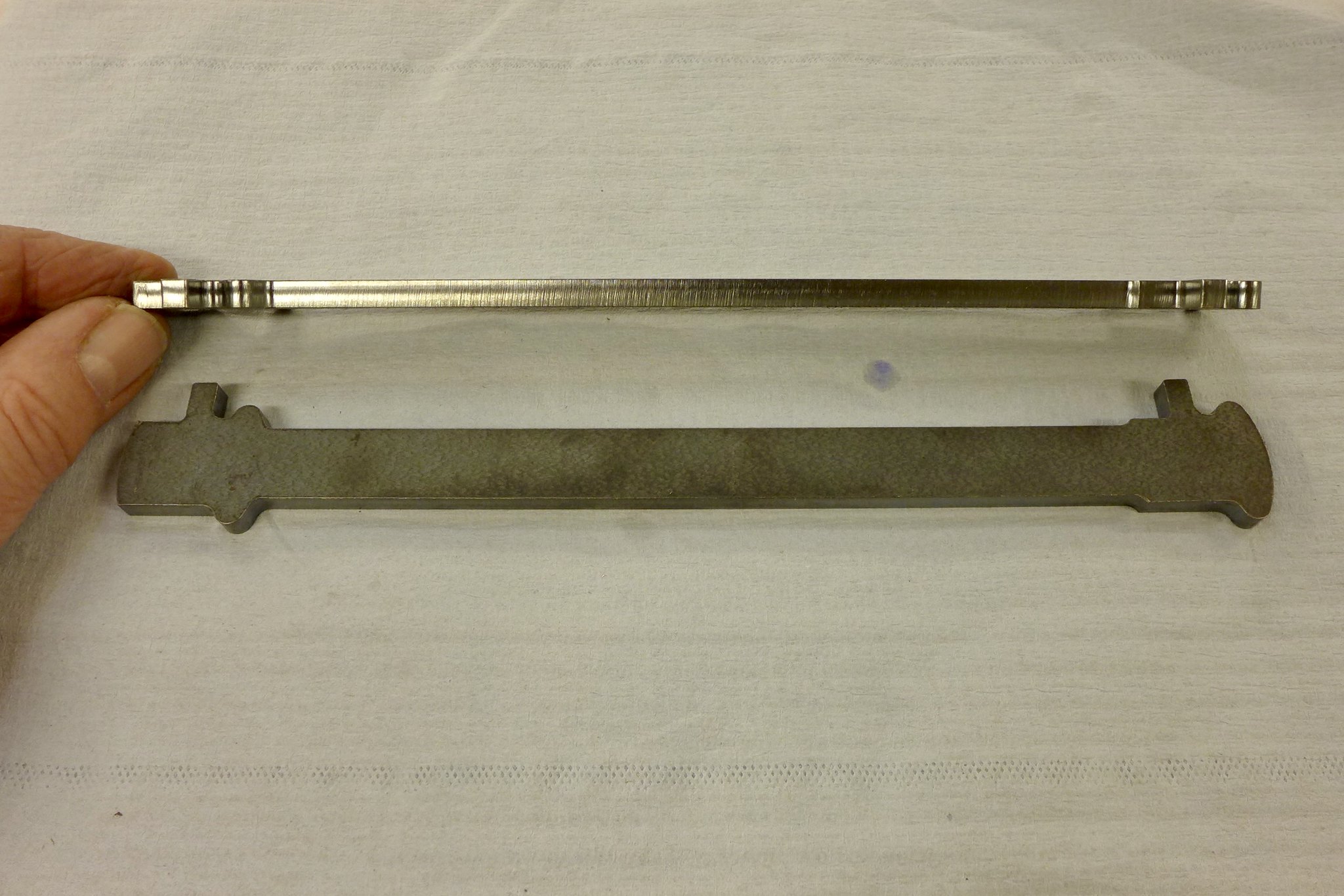 fullsizeoutput_681 fullsizeoutput_681 by Malcolm HARWOOD, on Flickr In the end i reverted to good old draw filing plus emery. I don't know if this makes a huge difference as the rods will be painted and the laser cut marks would not be seen. But, I guess, I will always know that they are there. 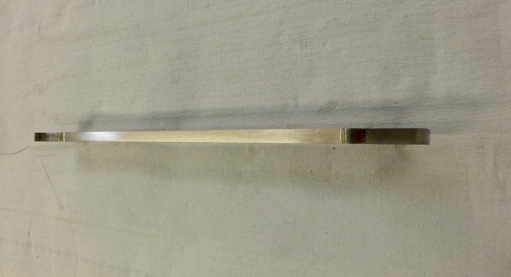 fullsizeoutput_684 fullsizeoutput_684 by Malcolm HARWOOD, on Flickr Reference the recent discussion about "spotting drills", I have to admit until 12 months ago I was not that familiar with them. Now I would not be with out one. All my holes are spotted with this 1/4" spotting drill. The holes are always spot on. No drill point wandering around. Yes. It is a pair of tool makers jacks retrieved from "that" tool box that has been lying under various benches in various locations for the past 5 decades. 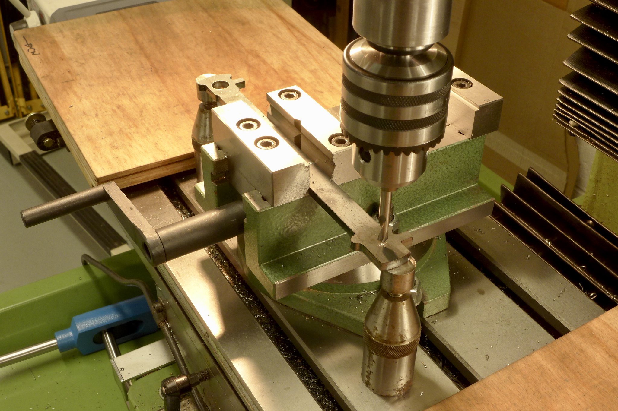 fullsizeoutput_682 fullsizeoutput_682 by Malcolm HARWOOD, on Flickr Cutting the "sausage" slots for the brasses was relatively straightforward. 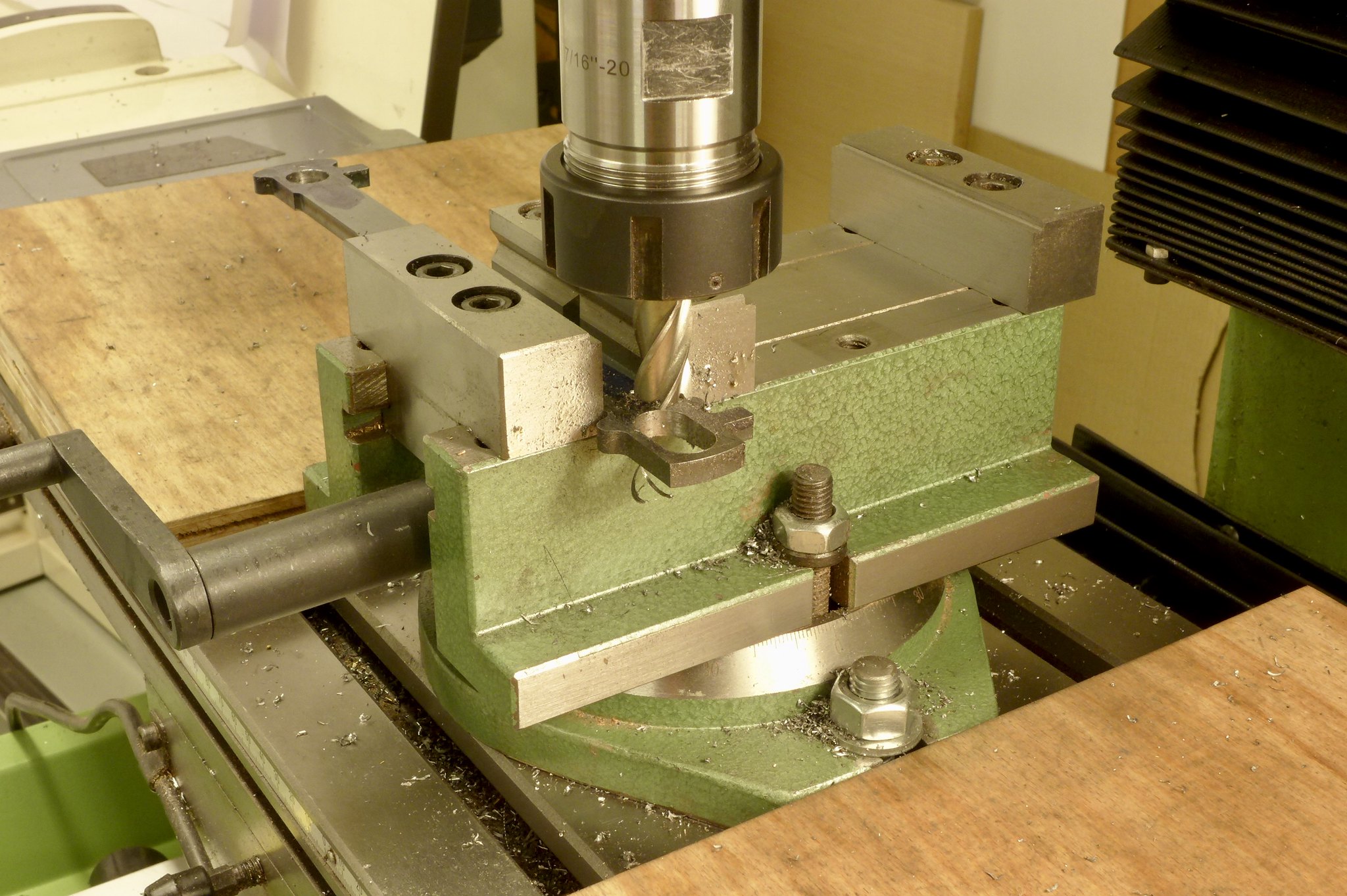 fullsizeoutput_685 fullsizeoutput_685 by Malcolm HARWOOD, on Flickr This was bit of fun. Cutting a 3/32" dia x 1/2" long slot for the cottter pins.The above mentioned hard skin I though might break these small cutters but gentle feeding worked OK. The cotter pins seem to take an age to make, especially fitting them into their slots. Another 2 hour job that suddenly morphs into 2 days! 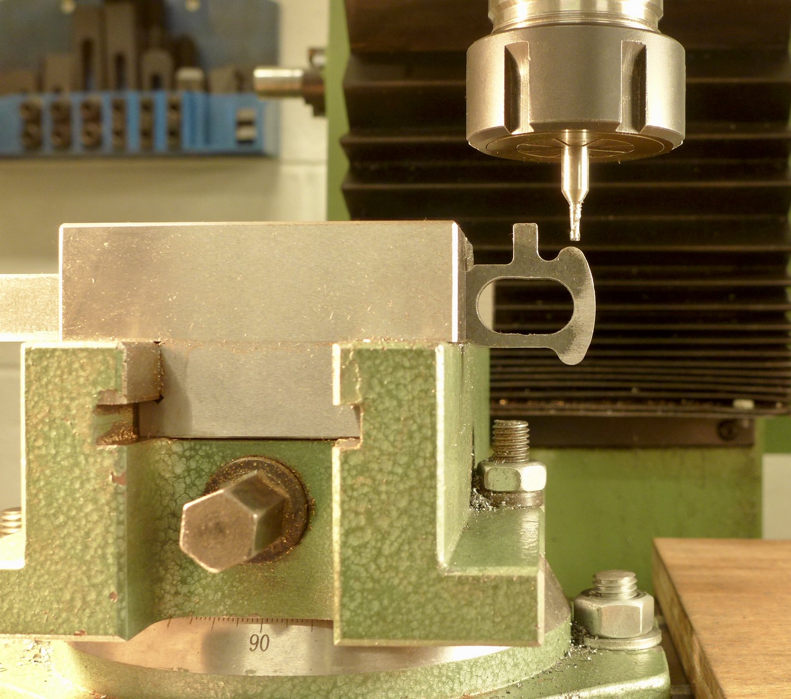 fullsizeoutput_687 fullsizeoutput_687 by Malcolm HARWOOD, on Flickr Next post will be the making of the coupling rod brasses and interpreting Don Young's non scale drawings, plus the difficulty with milling the reverse side of the connecting rods. What's difficult in that I hear you say. Stay tuned and I will explain! Thanks for reading Cheers Malcolm |
|
rrmrd66
Part of the e-furniture
Posts: 339
|
Post by rrmrd66 on Jan 17, 2018 16:57:37 GMT
Afternoon All. 3 o'clock one morning. I awoke in a sweat! Had I considered Euler's Buckling of Struts? What would happen if cheap white plastic legs on a kitchen cabinet decided that a very wobbly bench drill weighing 40kg+ was too much and collapsed . Worse still what if I was stood somewhere near when it happened. Like pulling the quill feed handle down. Serous injury may occur to the workshop floor. Perhaps even the operator! I was so concerned that upon getting up I immediately put 4 more (black) legs under the cabinet. It was still very wobbly so more long term action was needed. You see it all started when a very good friend of mine said he would like me take his Harrison M300 lathe away. For nothing! Well you don't get an offer like that every day, do you? The lathe eventually arrived and with help from Newton Tesla got it running on my single phase supply via an inverter. You can see it on the wall. The lathe has actually turned out to be shall we say, "tired". I had a charming ex Harrison's engineer come and visit to give it a health check. Bit like the doctor when they suck their teeth and say " well, what exactly did you have in mind bearing in mind your state of health". Any how, that's another story for another day. I can use it for rough turning and finish off on my reconditioned Super 7. A bed regrind and all new saddle innards is probably the only way to go. At a cost! To get the M300 lathe into my workshop I had to temporarily take the bench grinder off its cabinet and slide the bench drill over from the adjacent large wooden bench that had been home to a mostly unused Myford wood lathe. Because the drill is deeper that the cabinet top it was skewed to the left making the on/off buttons difficult to reach. Thus a visit to the builders merchant and several lengths of "4x2" CLS plus an old kitchen worktop and two days later I now have a wobble free drill stand and the grinder is back on its kitchen cupboard.  fullsizeoutput_67e fullsizeoutput_67e by Malcolm HARWOOD, on Flickr I can now return to the 5" Hunslet where I have recently achieved the milestone of mounting the valve gear into the frames and axle. Well most of it. Pictures to follow shortly as soon as I have completed the reversing pole. Thanks for reading this diversionary tale. Cheers Malcolm |
|
rrmrd66
Part of the e-furniture
Posts: 339
|
Post by rrmrd66 on Jan 10, 2018 16:16:17 GMT
Evening all Progress on the Hunslet build. The two sets of Stephenson's valve gear is more or less finished, as shown below, mounted on dummy shafts. The DY drawings are not too helpful in reassuring me that this is assembled correctly. However Hunslets for sale on the internet (Station Road Steam is good) have good close ups of all parts of these engines, so I think this is OK. Just a few rivets to finish and a few split pins to fix . There is a lot of fitting and "easing" to be done to get everything moving smoothly. 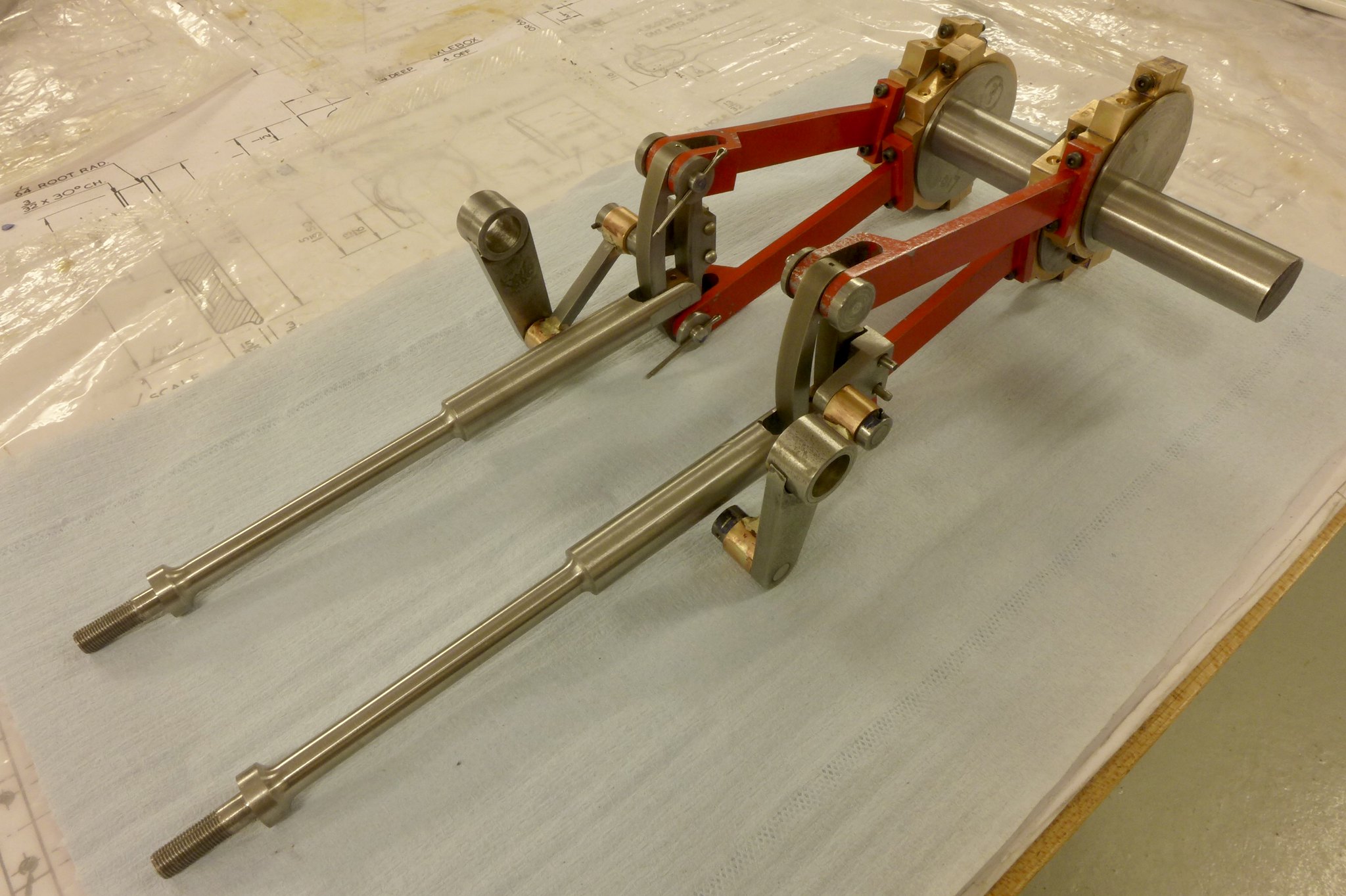 fullsizeoutput_677 fullsizeoutput_677 by Malcolm HARWOOD, on Flickr The pole reverser is a treat if you like making small intricate mechanisms. This is as far as I have got. I am leaving the notches until I see where full forwards and full reverse is when the reach bar is finished (currently under manufacture). Again a lot of fitting to be done on this. The leaver and guide bars at the base of the unit are to drawing and for the cylinder drain cock actuator rods. 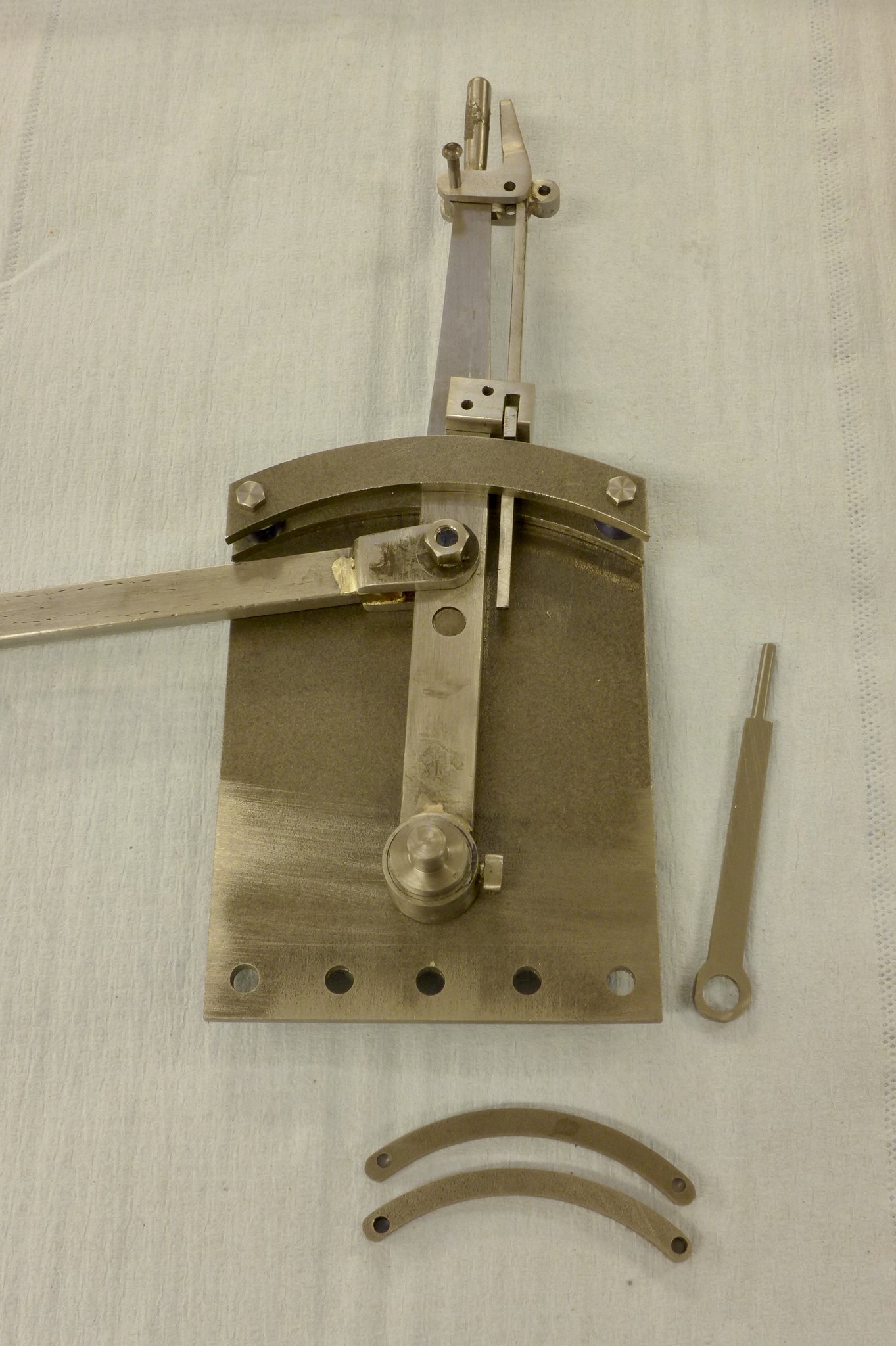 fullsizeoutput_679 fullsizeoutput_679 by Malcolm HARWOOD, on Flickr Almost to the point of mounting the valve gear into the frame and see if it all fits. I hope so! You can see one half of the reach rod, which I think has to mounted outboard of the frame. Not as I have it hear. There has recently been some threads about rotating build stands. This is my attempt at one made from two Machine Mart 1 ton car jacks ( over specified but cheap). Apologies to all the advanced manufacturing fraternity. This is based on the teachings of Professor Miuayga* of Tokyo School of Advanced Technology The DY Hunslet has dumb wooden buffers and countersunk wood screw holes on the buffer bars.The build is taking place in what is my furniture workshop ans so there are all sorts of bits of wood kicking about hence the oak plummer blocks! The engine can be raise and lowered with the hook seen lying on the base board and mounted in a hand held electric drill if speed is needed. The 8x45 degree rotary stop needs a little finessing but works fine. 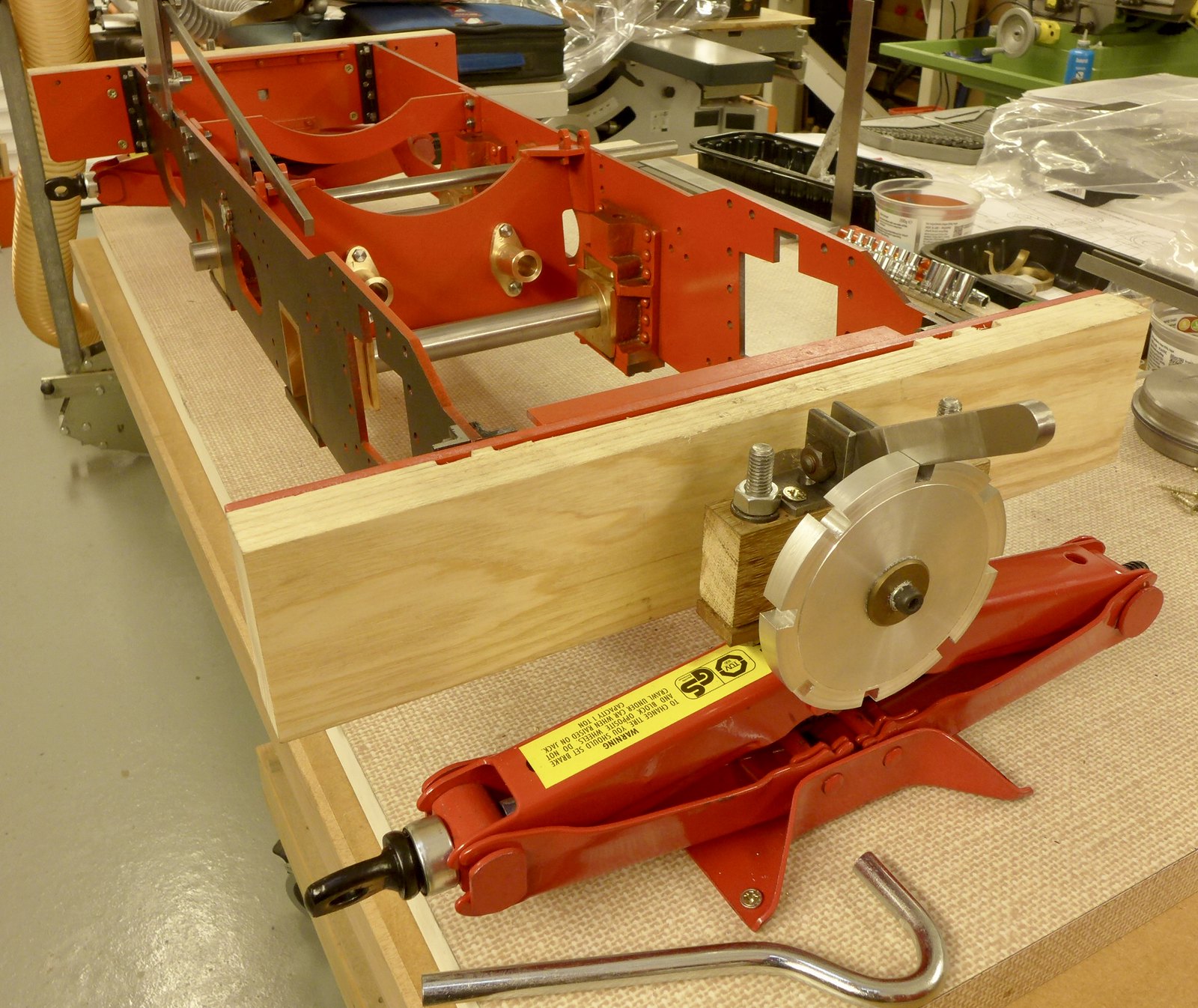 fullsizeoutput_67b fullsizeoutput_67b by Malcolm HARWOOD, on Flickr This is a view from the other end of the build stand showing the reach rod being "eyed up" prior to cutting to length 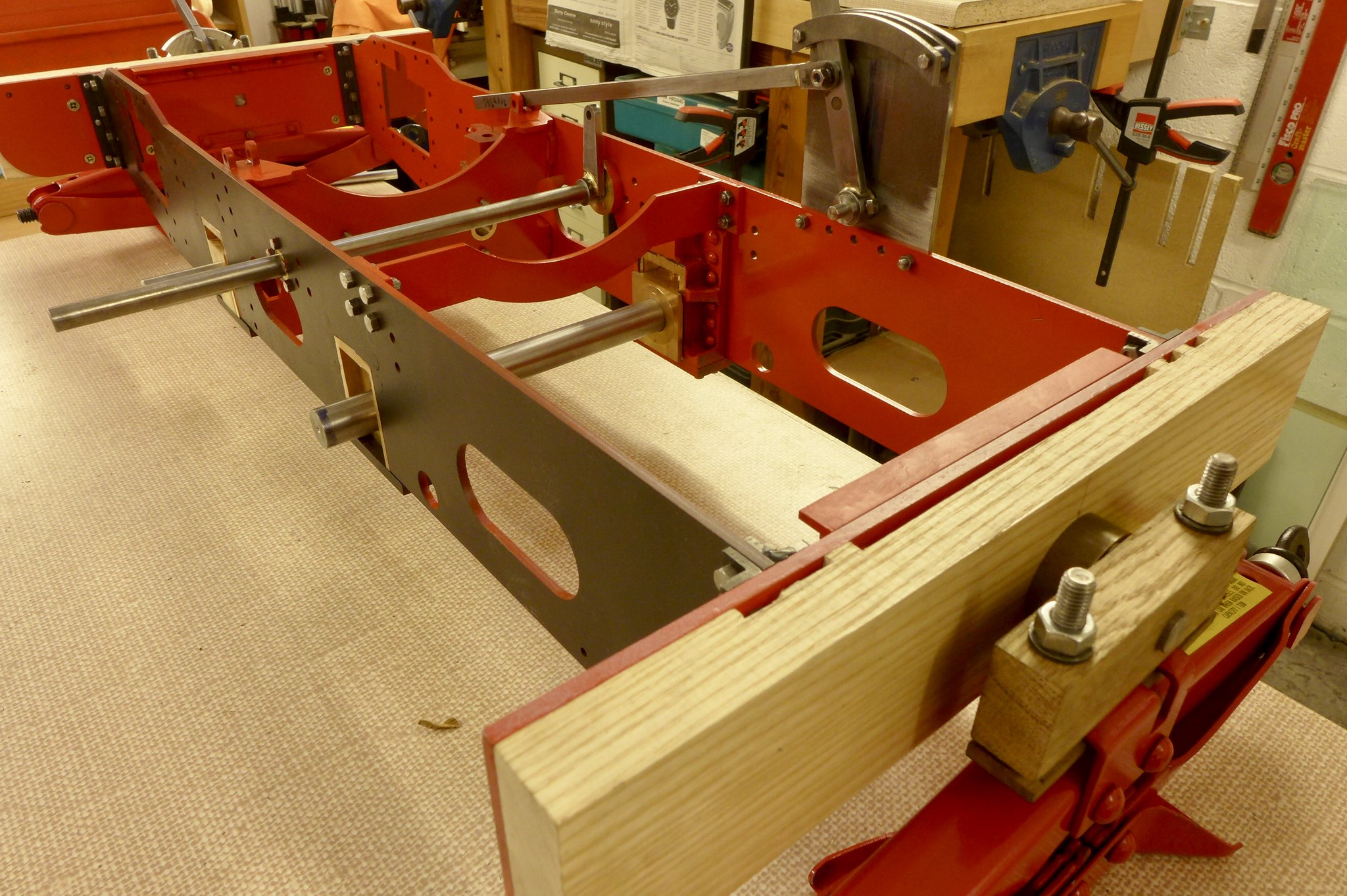 fullsizeoutput_67c fullsizeoutput_67c by Malcolm HARWOOD, on Flickr Next to do after fitting the valve gear and making sure it all lines up is to make a start of the valve chests and cylinders. I think I can then at last finally drill the frames and fit the valve motion plate. Thanks for reading cheers Malcolm Miuayga* (Make It Up As You Go Along) |
|
rrmrd66
Part of the e-furniture
Posts: 339
|
Post by rrmrd66 on Jan 1, 2018 15:22:38 GMT
Thinking of getting one of these, but am confused ovder the variety of drills available Anyone out there have a good knowledge on the best all round one to get... Hello silverfox I originally bought a Dremel Multi drill part number 10.000-33.000 for routing the electric light cable channels in my wife's Victorian miniature dolls house floors (you know the type that costs about the same as a full size house once you get hooked on 1/12 scale furniture!). No problems and ideal for the purpose. You get a full set of drills and cutters plus collets. Prior to starting my 5" gauge Hunslet build I decided to build an 8 day weight driven grandfather clock plus cabinet. Many holes in clocks are as small as steam engines (spit pins etc) and my pillar drill was just too heavy duty and my vertical mill was lacking "feel" with 1/16' dia drills, although I have found that with very careful attention to work holding and accurate centering good results can be achieved . I decided that I would give the Dremel Work Station 220 a go ( P. No. 200 3000 4000). This turns the basic drill tool into a vertical drilling machine. As long as you treat it with respect and pack it up here and there to get the alignment near to vertical as possible it does the job. Thus I would recommend the Dremel but with the above mentioned caveats. However in the search for greater control and accuracy have you looked at the universal pillar tool of dear old George Thomas with the optional sensitive attachment? I think that I might just treat myself to the Hemingway kit(s) as I have a small variable speed motor available: www.hemingwaykits.com/cgi-bin/sh000029.pl?REFPAGE=http%3a%2f%2fwww%2ehemingwaykits%2ecom%2f&WD=drill&PN=Universal_Pillar_Tool%2ehtml%23aHK_201270#aHK_201270As always you pay your money etc etc Good luck Malcolm PS Racinjason. Maybe this thread should be in tools and tooling? |
|
rrmrd66
Part of the e-furniture
Posts: 339
|
Post by rrmrd66 on Dec 24, 2017 8:07:07 GMT
Just a brief "Seasons Greetings" to all the wonderful contributors to this forum.
As a new comer to this hobby/sport/pastime/torture may I say that your combined wealth of knowledge and experience is truly inspirational.
Special mention has to be made of "Roger", who I think we all agree is something else. The coal shovel was, well I don't know what, just awe inspiring.
Good health to all in 2018
Best Wishes
Malcolm
|
|
rrmrd66
Part of the e-furniture
Posts: 339
|
Post by rrmrd66 on Dec 18, 2017 7:59:41 GMT
Hello Steve
Ive just ordered some as well.
The proof of the pudding etc etc!
Cheers
Malcolm
|
|
rrmrd66
Part of the e-furniture
Posts: 339
|
Post by rrmrd66 on Dec 17, 2017 10:14:27 GMT
|
|
rrmrd66
Part of the e-furniture
Posts: 339
|
Post by rrmrd66 on Dec 17, 2017 8:03:26 GMT
Hello Julian
Thanks for the nice words.
We might just as well use the power of modern technology if it helps (i.e. computer spread sheets).
There is a wonderful black and white photo somewhere of two draftsmen working on a full size valve motion simulator at one of the loco works in the 30's(?). Somebody will know the one I refer to?
A bit like the wonderful piece of furniture that the NRM has in their storeroom used to signal men. More Chippendale than Gresley.
Cheers
Malcolm
|
|
rrmrd66
Part of the e-furniture
Posts: 339
|
Post by rrmrd66 on Dec 16, 2017 8:15:04 GMT
Thanks Jools
I need all the encouragement I can get!
Malcolm
|
|
rrmrd66
Part of the e-furniture
Posts: 339
|
Post by rrmrd66 on Dec 15, 2017 20:32:40 GMT
Good Evening. Once again daily effort appears to have produced not much progress. However, lets get up to date with this "simple" build. Some time ago Julian Atkins offered to run the valve gear control assembly through one of the optimised spread sheets. The one he chose was Prof Bill Hall's. The adjustment to the dimensions of some of the expansion link/trunnion/lifting arm assemblies were minor but having fought my way though Don Ashton's treatise upon Stephenson's Valve gear I decided to give it a go. Dear old Don Young, the designer of this Hunslet NG engine, decided in his haste/wisdom(?) to make 1"+3 5/8" = 4 7/8". This of course should be 4 5/8" and so the expensive water jet cut expansion links supplied by a company, most people on this forum hold in high regard, was not able to have them re-cut to the new dimension. Fortunately, when you have run a seal manufacturing and distribution company for 25 + years then you do have a few contacts who are still good friends. One such ex employee now works for an international company deeply involved with sealing in the petrochemical industry and has all sorts of wonderful machine at his disposal. Thus below, on the left hand side of the picture, we have an expansion link and die block machined by what I call "spark erosion" ,but it's posh name is EDM (electrical discharge machining) The results are plain to see. The expansion link on the right is the water jet cut original version. As you can see the die block has been also EDM machined to a matching radius and runs very smoothly in the expansion link. They also kindly put the rivet holes in for me. I have fitted the P.Bz bearings. Incidentally the lifting arm trunnion, in its partly machined state, has what I have dubbed the "Atkins shoulder". A tip from Julian to help locate the trunnion whilst spotting through to drill the 3/32`' rivet holes. 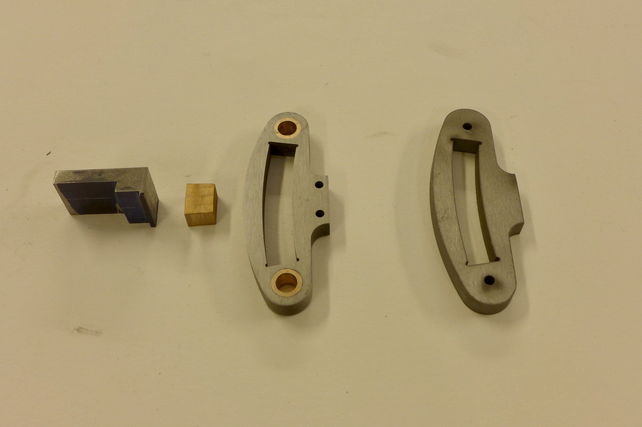 fullsizeoutput_672 fullsizeoutput_672 by Malcolm HARWOOD, on Flickr The die bock is in fact quite small. 1/4" thick and 13/32" in length. It needs a 3/16" dia. hole to take the pin that fixes it to the intermediate valve spindle and as I only had one per link I thought that this was one of those ideal opportunities to make a big mistake. I found the center on the surface plate with my height gauge, made an improvised clamping arrangement from wood and screws and centred it by with a centre drill prior to drilling. The SOBA drill vice whist being cheap is unfortunately not that accurate and tends to clamp untrue in its jaw shoulders. I should point out that the wording on the drill tin is nothing to do with my affiliation to a certain southern soccer team. 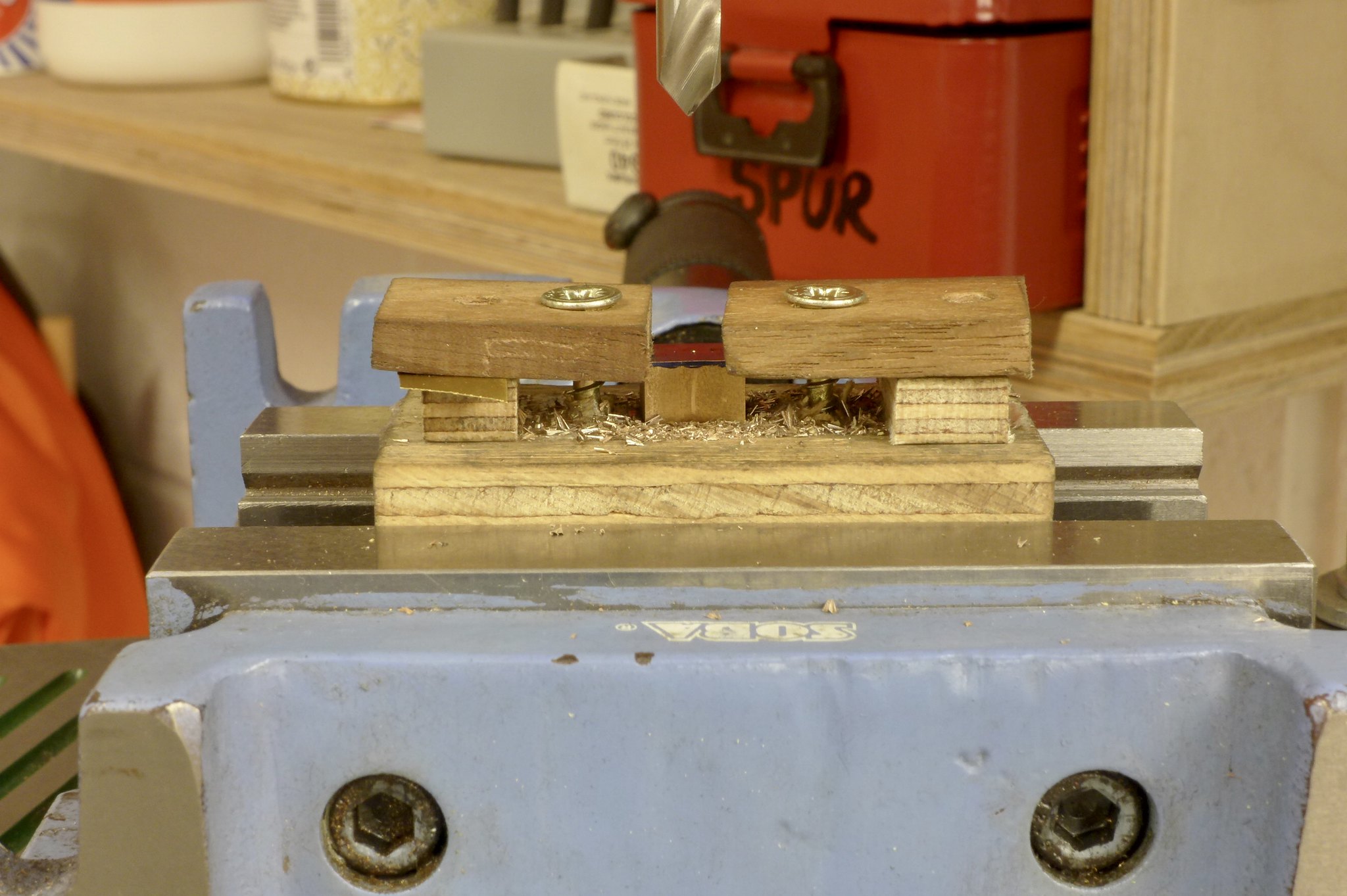 fullsizeoutput_673 fullsizeoutput_673 by Malcolm HARWOOD, on Flickr The outcome of all this waffle is that I now have two edm expansion links, together with die blocks, and two trunnion arms that have been modified to place the centre of the pin about 0.100" in front of the center line of the radius slot ( to the right of the bisected line if you are interested) plus rivet holes drilled wit the assistance of the Atkins shoulder. 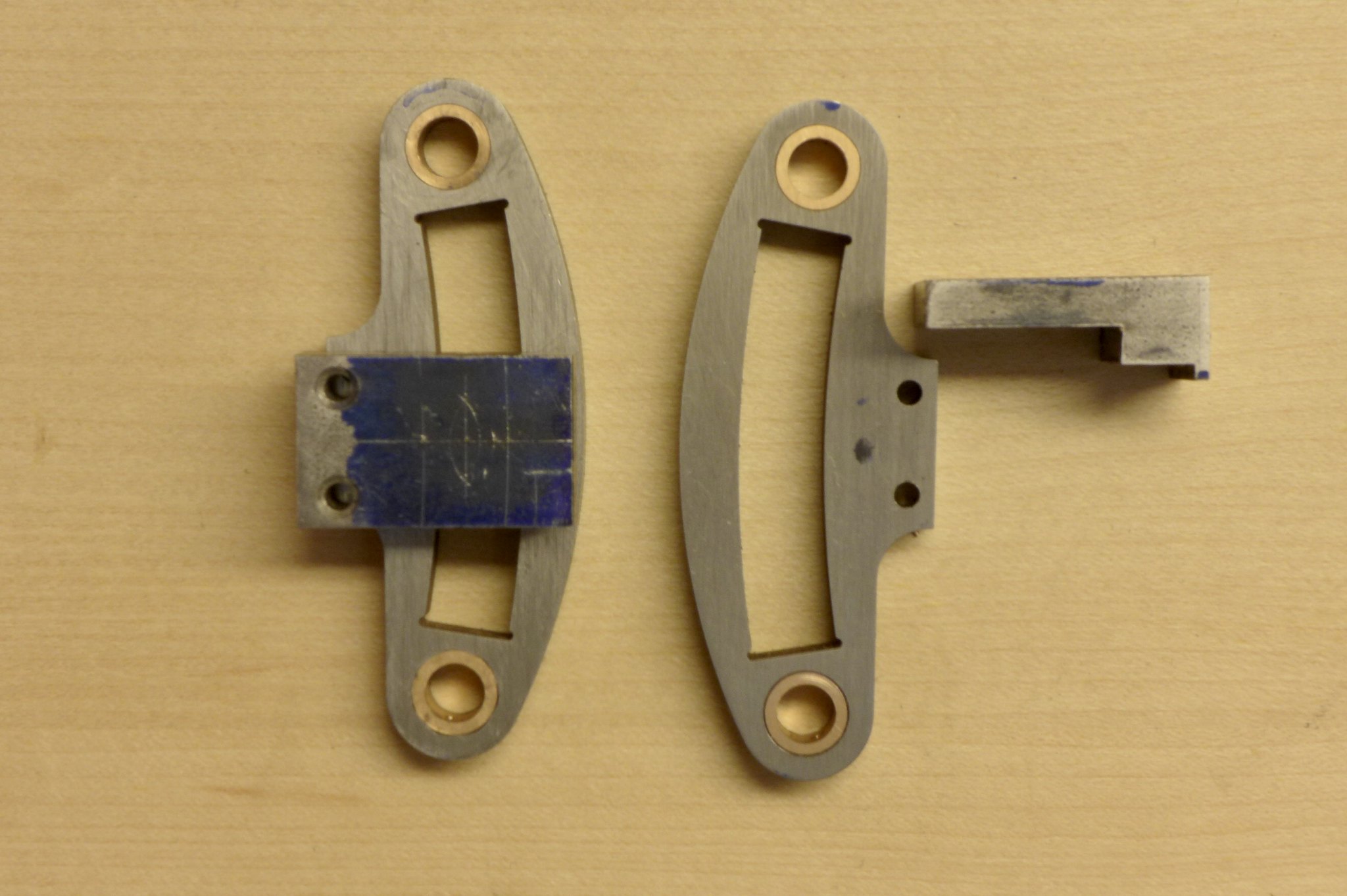 fullsizeoutput_674 fullsizeoutput_674 by Malcolm HARWOOD, on Flickr Eventually after much fettling, filing and soldering we have a kit of parts with which to put the sub assembly together. Here we see work in progress. The int. valve spindle in pinned by an interference fit pin. The hidden die block is free to move on the pin and slide in the slot. Next step is to join the eccentric strap con. rods to the ends of the expansion links and Robert is your uncle. I will report back in due course 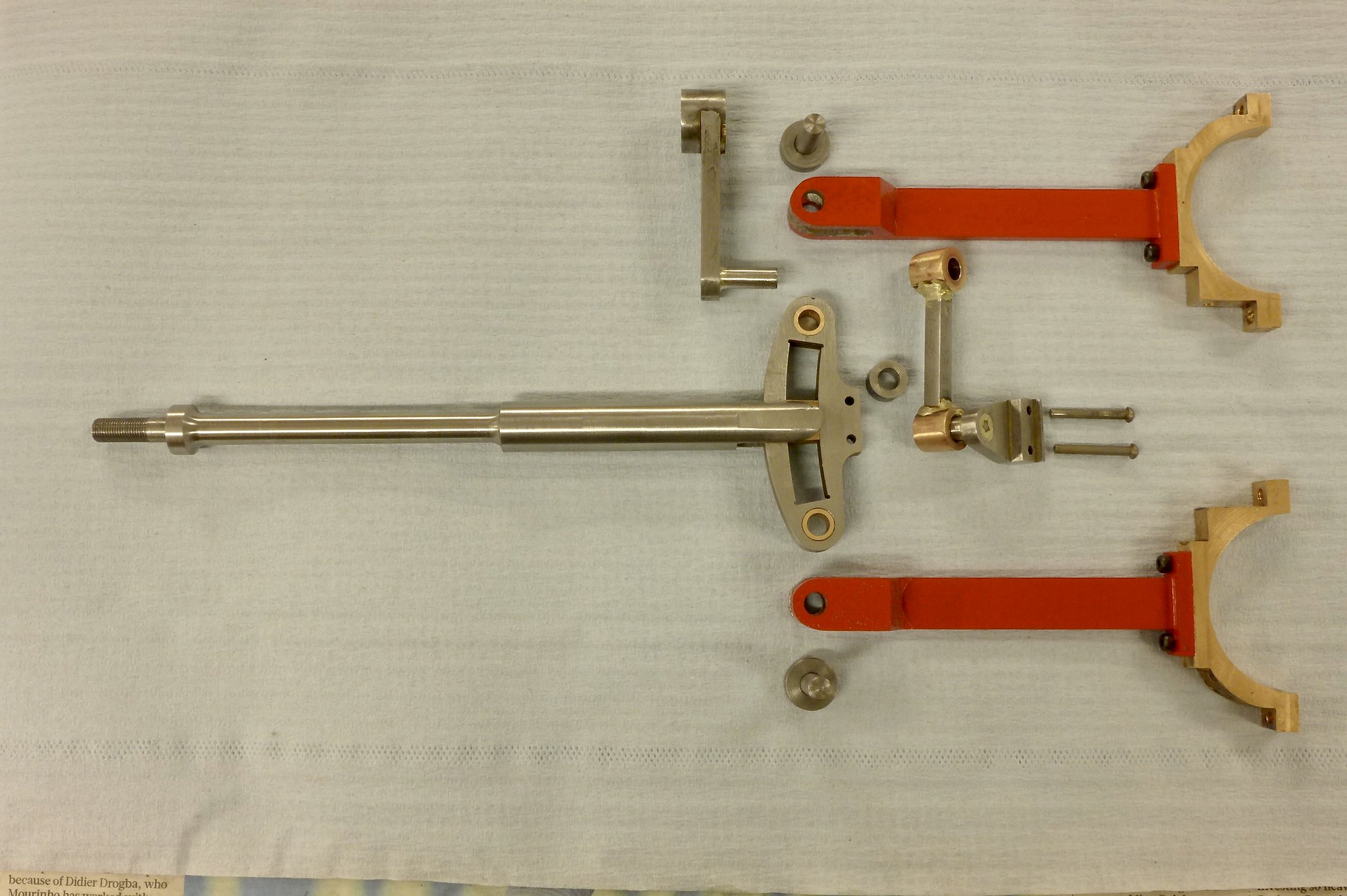 fullsizeoutput_675 fullsizeoutput_675 by Malcolm HARWOOD, on Flickr Thanks very much for reading my ramblings Cheers Malcolm |
|
rrmrd66
Part of the e-furniture
Posts: 339
|
Post by rrmrd66 on Dec 8, 2017 7:49:23 GMT
|
|
rrmrd66
Part of the e-furniture
Posts: 339
|
Post by rrmrd66 on Dec 8, 2017 7:39:07 GMT
Hi Orville
I suggest humidity and thus rust formation is a bigger threat than ambient heat.
My last workshop at our old house was lined out similar to yours.
I had a small dehumidifier (Ebac) running 24/7 and an oil filled radiator (1-2kw) which was on when I was in there during the winter months.
I find that anything lower than 17C for working in gets uncomfortable, but you guys in Lancashire might be tougher than us Yorkies.
Make sure that you check out air-tightness as otherwise you will in effect be drawing outside air in and trying to dehumidify the universe!
Boots with thick socks and a body warmer are a help. Anti-fatigue mats (Axminster) on the floor, where you stand for any length of time (lathe perhaps?), keep feet warm and reduce tired legs.
Bit spoiled in my new purpose built workshop, attached to the house, complete with underfloor heating connected to the house. Still have the dehumidifier running though.
Good luck
Malcolm
|
|
rrmrd66
Part of the e-furniture
Posts: 339
|
Post by rrmrd66 on Dec 7, 2017 19:12:44 GMT
Thanks for this Lisa.
I think I prefer the 45deg tool bore. This will make measurement with a "mic" more precise as the anvil, on the non tool side of the bar, has a perfect cylindrical surface to register against.
None the less thanks to all the above people for lots of good tips and showing interest.
I think that this will be a good project to christen my "new" (1976) Harrison M400 with.....that is when I have removed 40 years worth of swarf/oil/dust but fortunately no rust.
Cheers
Malcolm
|
|
rrmrd66
Part of the e-furniture
Posts: 339
|
Post by rrmrd66 on Dec 2, 2017 14:29:01 GMT
Thanks for that simplyloco.
I am of an age that I can remember Granny buying a black and white TV for the Queens coronation (and a bit before that!)
Cheers
M
|
|
rrmrd66
Part of the e-furniture
Posts: 339
|
Post by rrmrd66 on Dec 2, 2017 11:58:44 GMT
What is an OP. I hope it is not "old person".
Actually I think I have caused confusion. It is however good to see everybody chipping in with their advice and comments.
I have initiated two separate threads.
One is in "tools and tooling" regarding a between centres boring bar asking for a copy of an old magazine. Model Engineers Workshop Issue 136 March 2008
The other is in this "general" section asking for a supplier of ME nuts, which I now know is impossible. The nuts are in fact for the valve spindle dog leg/intermediate valve spindle on the Stephenson's valve gear on my Don Young 5" NG Hunslet.
Maybe best if we all leave it at that, but thanks for your interest.
Cheers
Malcolm
|
|
rrmrd66
Part of the e-furniture
Posts: 339
|
Post by rrmrd66 on Dec 1, 2017 10:11:01 GMT
If you make your own you can get the right height of nut, commercial nuts in small sizes are often too thin. If need be a reduced hexagon can be used to get a scale looking nut in a tight space with an over size stud. isc Hi isc Yes good point. Thanks Cheers Malcolm |
|
rrmrd66
Part of the e-furniture
Posts: 339
|
Post by rrmrd66 on Dec 1, 2017 7:34:12 GMT
Hi Julian and David.
Say no more. I'm on with it.
Thanks for your interest
Malcolm
|
|
rrmrd66
Part of the e-furniture
Posts: 339
|
Post by rrmrd66 on Nov 30, 2017 17:43:16 GMT
Hi Bob
Thanks for all that. Very useful information.
Wow! What a lot I have learned since April.
Thanks for your interest.
Cheers
Malcolm
|
|
rrmrd66
Part of the e-furniture
Posts: 339
|
Post by rrmrd66 on Nov 30, 2017 16:24:43 GMT
Hello D
Not unhelpful at all.
In fact at least one jump ahead of you. I had found the recommended Journeyman's web page earlier on today.
There are several items on the Don Young 5" Hunslet I am building that call for 1/4" x40 tpi threads. Maybe in the '70's ME fastenings were easy to source.
As you will have noted I already have a set of taps and dies ex Tracy tools from the Midlands ME exhibition, so not a big deal to make some nuts up.
I can obtain 7/16" or 0.445" A/F hex bar from M Metals in Darlington so will go that way unless someone can tell me a supplier.
Thanks for your interest.
Cheers
Malcolm
|
|
rrmrd66
Part of the e-furniture
Posts: 339
|
Post by rrmrd66 on Nov 30, 2017 13:16:33 GMT
Afternoon everybody.
It would appear that ME thread nuts (e.g. 1/4"x40tpi) are like hens teeth.
Reading other much older forum posts it would appear that this had been a long term problem
Is there anybody out there who has a present day supplier.
Cheers
Malcolm
PS I have taps and dies from Tracy Tools so I can make my own if pushed. Have already cut the thread for the "bolt" so need nuts!
|
|


