|
|
Post by GWR 101 on Mar 10, 2015 23:50:37 GMT
Thanks Ed will give it a go, and report back. Regards Paul
|
|
|
|
Post by Jim on Mar 11, 2015 0:45:01 GMT
I've just had another look at your photos Paul and it looks to me as if the 'wall' between the big hole the small hole close enough to open up with a jeweler's saw first up.
As Ed say's a Jeweler's saw will be your friend.
Jim
|
|
|
|
Post by GWR 101 on Mar 11, 2015 22:47:04 GMT
Hi Jim, yes I have managed to join the two holes into a pear drop shape. I believe they are ok and as they will not be a visible part I have made them functional rather than decorative. I have attached a photo and fortunately they are not too clear, I can't believe how many parts there are to this piece of the engine. I still have a few more bits to machine and then adjust the various pipe lengths to make sure everything fits and is in the correct place, in shot is one of the stainless springs and some stainless 2 mm countersunk screws to secure some of the bits together. It will probably take another 2 to 3 days to get it assembled so unless I hit any problems I shall not have anything to show until then. Many thanks to all for their help in making this. Regards Paul 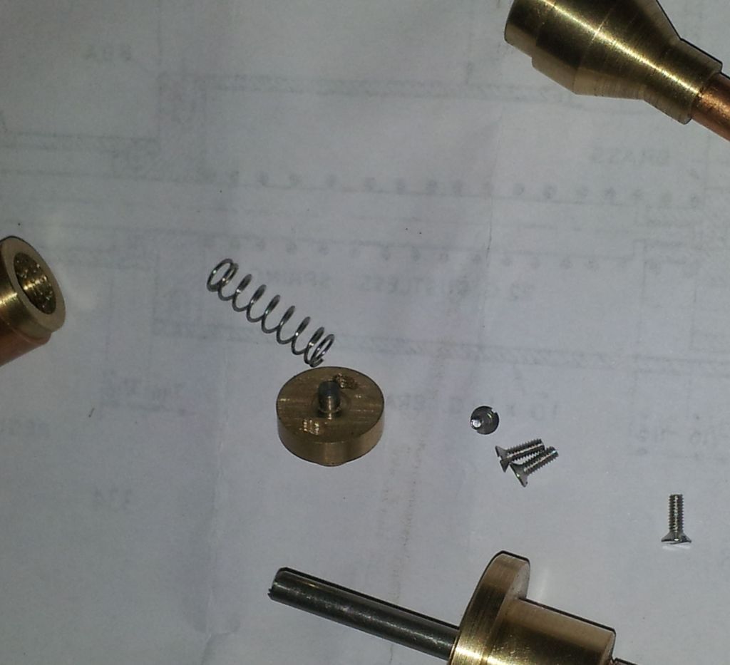
|
|
|
|
Post by GWR 101 on Mar 16, 2015 12:20:47 GMT
I have managed to make some progress with this and believe I am close to putting it all together but have encountered a bit that I am not sure I fully understand how it's assembled.
To summarize the boss on the cab end is bolted to a boss in the boiler, however at the smoke box end there is an adaptor that screws into the boiler with a 3/8" thread from the smoke box side onto this is bolted a flange that feeds to the super heater. This adaptor is internally screwed 1/4" to accept the feed pipe from the regulator, which is inserted from the cab end.
So the question is :- I assume that when screwing the regulator in from the cab it has to screw into the adaptor at the smoke box end and provide a steam tight fit whilst at the same time the boss on the cab end has to seal on the boiler boss and the securing holes line up. This sounds like trying to juggle 3 balls whilst riding a unicycle blindfolded with one hand tied behind your back.  Regards Paul Regards Paul |
|
|
|
Post by GWR 101 on Mar 16, 2015 18:16:53 GMT
Just to clarify I have attached a photo, the flange on the bottom right end fits into the boss in the back head, the holes are still to be drilled. The top right is the part that screws in from the smoke box end and accepts the screwed small diameter copper pipe that is attached to the regulator and fed in from the cab end. Well at least that's how I think it is assembled. Any help or advice greatly appreciated, Regards Paul 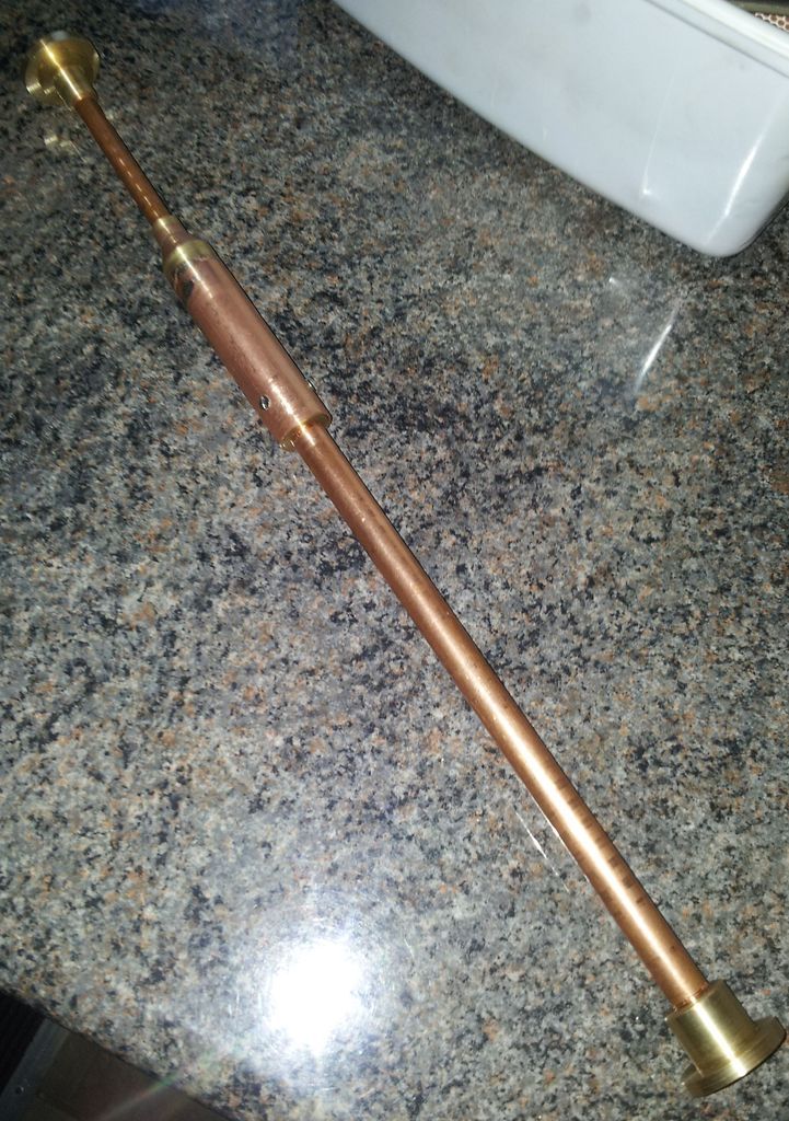 |
|
|
|
Post by Jim on Mar 16, 2015 21:01:09 GMT
That looks a lovely piece of workmanship Paul. Can't help you on how it works sad to say.  Jim |
|
uuu
Elder Statesman
   your message here...
Posts: 2,857
|
Post by uuu on Mar 16, 2015 21:11:21 GMT
Are the inner and outer threads on the smokebox end the same pitch?
If so, start by passing a long thin rod right through the boiler. Take off the smokebox bush, pass your regulator assembly over the thin rod and into the boiler, withdrawing the thin rod gradually as you push the assembly in. When it's fully home, the thin rod will still be sticking out of the front, an you should be able to pass the bush over it, to engage in both the copper pipe and the threaded boiler fitting.
Wilf
|
|
|
|
Post by GWR 101 on Mar 16, 2015 22:49:24 GMT
Jim thanks, getting there slowly, can't believe how much work there is in what is basically a tap.
Hi Wilf, yes the threads are 3/8" X 40 tpi. on the outside and 1/4" X 40 tpi inside where the furthermost forward part of the regulator pipe screws in. I like your idea for lining it up and easing the assembly, and I will certainly use that method.
What really concerns me is that I need to get a good seal at the smoke box end with two threads coming in opposite directions such that the complete assembly also seals on the boss on the back head which is some 12" away. It has occurred to me that the boss at the back head end which is secured by some bolts is actually screwed onto the regulator assembly (3/8" X 40 tpi.)so I could possibly get some small adjustment in length here but that would loosen the thread contact. Regards Paul
|
|
jma1009
Elder Statesman
  
Posts: 5,917
|
Post by jma1009 on Mar 16, 2015 23:07:48 GMT
hi paul,
try a few dummy runs to start with. the LBSC method is a real pain, and am sure many will tell you of exasperating problems, or conversely others will say every thing fits perfectly with no problems. for final assembly i would use loctite but be quick!
cheers,
julian
|
|
|
|
Post by GWR 101 on Mar 16, 2015 23:26:34 GMT
Hi Julian and thanks, yes following the old advice of measure twice and cut once is certainly the way forward. I am also thinking of trying an out of boiler trial run with compressed air to see how the valve works. Don't know if I have this correct but as the complete assembly is inside the boiler surrounded by pressurised steam then surely the ends are where a good seal is vital ? Regards Paul
|
|
|
|
Post by Deleted on Mar 18, 2015 8:50:13 GMT
Hi Paul ,
Well I found making one of these regulator assemblies difficult years ago so you are not alone in your experience !
Good principle in engineering is to start at the beginning and go on to the end so :
Tighten up and seal all the threaded joints into the regulator itself and into the backhead flange .
Assemble the regulator into the boiler temporarily . Set it so that steam inlet hole is on top and drill and tap the backhead fixing holes .
Bolt up tight .
See if steam pipe at smokebox end is in right place . Take out regulator and bend steam pipe a little if nescessary .
Screw on/in smokebox flange . Should go reasonably easily . If not look for threads too short or bottoming etc .
Screw home smokebox flange hard . Make sure there is something to hold onto on smokebox flange . I made a little prong tool to engage the stud holes . Could also provide flats or make hex .
Aligning rod is excellent idea .
Be aware that these assemblies with multiple things screwed into things can come apart anywhere when dismantled so make sure that joints never intended to come apart again are absolutely tight .
Best remove regulator after successful trial assembly and then use sealant on flanges for final installation .
I note your comment :
Don't know if I have this correct but as the complete assembly is inside the boiler surrounded by pressurised steam then surely the ends are where a good seal is vital ?
A problem with this type of LBSC regulator is that they can potentially leak in so many places that it is best as a principle to make a good job of every joint .
I once saw an engine with a regulator of this type go off on its own with the regulator tight shut ! So make a good job of things .
It is possible to make a regulator assembly of this same general type but much less problematic - get back to us if you ever want to do one for another engine .
MichaelW
|
|
|
|
Post by GWR 101 on Mar 18, 2015 18:23:41 GMT
Believe it or not I think I am almost there, thanks to every one for their help and kind words of encouragement. Thanks Michael for your tips and suggestions which are most informative and welcome, as you will see I am now at the stage of preparing to drill the holes in the back head flange having assembled all the component parts of the regulator except for the gland nut and handle assembly at the back head end and the flange for the super heater pipes at the smoke box end. The feed pipe in the dome connection is causing me some concern, I have tapped the body 1/4" X 40 tpi. as show on the drawing but there are I feel insufficient threads to make an acceptable fit so I will have to modify this. My initial thought is to make a small PB bush to connect the pipe rather than screw it straight in, I can make this with an oversize taper thread which will be more substantial. When I am satisfied that the regulator assembly is satisfactory after several trial fits I will certainly be locking some of the threads as I can see the potential for problems with the number of screw threads involved. It is some consolation to know others have experienced some difficulties with this part, I did wonder if this was the first part made in a build there would be fewer locomotives built or at least a design change. Regards Paul
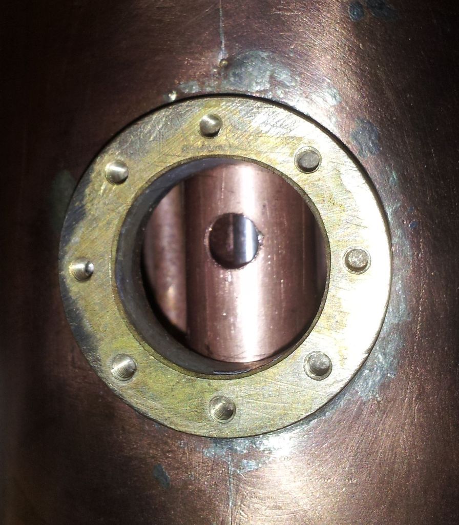
Regulator body feed pipe, the stainless control rod can be seen.
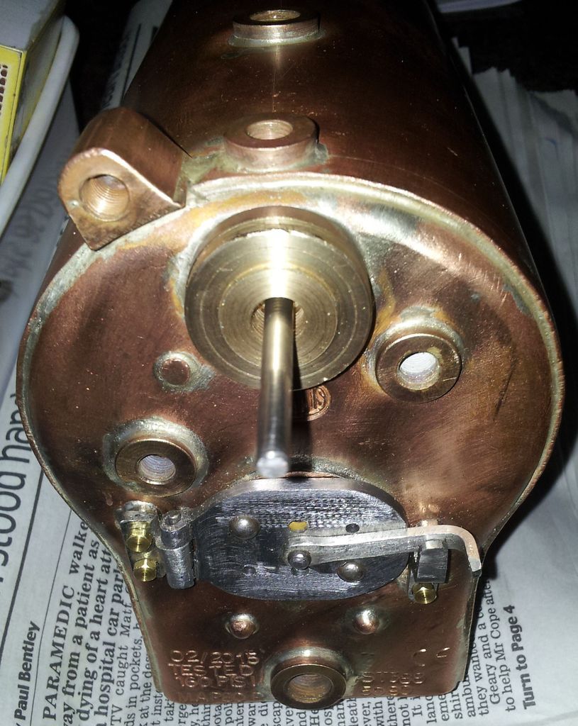
Control rod at back head flange.
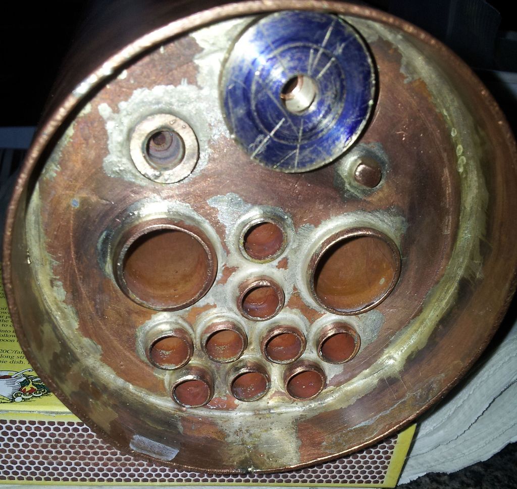
Smoke box flange for super heater flange, feed pipe from regulator can be seen in the centre. |
|
|
|
Post by ejparrott on Mar 18, 2015 19:10:23 GMT
The problem with putting a bush on is where is it going to fit? If you fit it on the outside, it won't go through the backhead bush, if you fit it on the inside, you can't fit the valve
|
|
|
|
Post by GWR 101 on Mar 18, 2015 19:44:05 GMT
Hi Ed, yes my initial idea was to go that way but for the reasons you mention it is not possible. I was going to make it so that it is attached to the vertical collector pipe and screws into the regulator body through the inner dome boss once it's in situ. I understand this doesn't strengthen the 5/8" screwed part but making it slightly larger and tapered I thought would provide a more stable fit. I can't see any alternative without redesigning the internal workings of the valve.
Wow just had an idea, what about if I make a collar which is a free fit in the bore with a taped hole to accept the pipe, this can then be screwed into to act like a "T" nut, a small flange on the upright pipe would then pull it into contact with the bore.
Like this :-

Apologies for the quality of the drawing, couldn't find a better fag packet  . Regards Paul . Regards Paul |
|
|
|
Post by Jim on Mar 18, 2015 19:58:31 GMT
You're certainly cracking along there Paul and the results look great.  Jim |
|
|
|
Post by GWR 101 on Mar 18, 2015 22:54:11 GMT
Thanks Jim, I am going to try out the idea for fixing the top feed pipe tomorrow, then make a Jig for drilling the flange holes, then make a handle and quadrant. The list is endless, well it would be if there was a list, too frightened to make one. Then I might have a couple of days on the trolley, oh and there is the little diversion of a trip to Wembley on Sunday cant miss that, 127 years in waiting!. Regards Paul
|
|
|
|
Post by GWR 101 on Mar 19, 2015 23:16:10 GMT
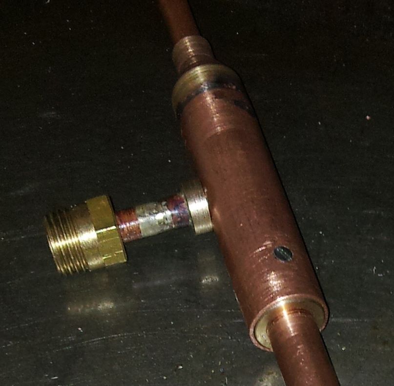
Just an update on the regulator, I have made a bush as my sketch and it appears to be a reasonable solution, it can be seen at the bottom right of the first photo. I then fitted it all together with a short length of pipe and an adaptor to try it on compressed air, well the air comes out of the correct place and no where else so I believe that's a start. What I have found is that the valve does not shut off so I need to take a close look the contact faces and possibly the strength of the spring to see if I can resolve this issue. Regards Paul 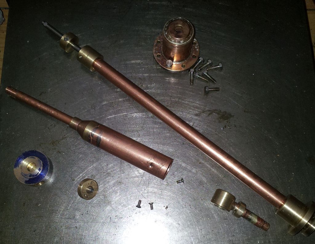
|
|
jma1009
Elder Statesman
  
Posts: 5,917
|
Post by jma1009 on Mar 19, 2015 23:31:39 GMT
hi paul,
i think that regulators are very difficult to get right in the smaller sizes. ive never made one yet that didnt leak on the hydraulic test. what you have encountered is what is often not (or never) in print and taxes all of us at some time or other! you are doing very well!
cheers,
julian
|
|
|
|
Post by GWR 101 on Mar 19, 2015 23:40:23 GMT
Hi Julian and thanks, I shall do my best to get this one sealing correctly before I proceed further. As I am only testing it on air I shall try various strength ordinary steel springs to ascertain what strength would be best, before obtaining a stainless one. Regards Paul
|
|
jma1009
Elder Statesman
  
Posts: 5,917
|
Post by jma1009 on Mar 19, 2015 23:49:44 GMT
hi paul,
if i might add a little tip re sealing of the valve face, apply micrometers blue and ONLY turn in the angle the regulator works - and mark one bit of the valve 'top'. dont turn the valve full circle. mimic what the regulator will do only. if any particular high spots emerge, i scrape them, otherwise use brasso again only the movement that the regulator imparts, with the valve assembled only one way.
i still have to blank off the steam pipe to the steam chests for the hydraulic test!
if you use brasso dont let it go dry and keep it 'fluid'.
cheers,
julian
|
|