|
|
Post by springcrocus on Dec 19, 2015 23:10:44 GMT
...and help the wife with the gardening, you seemed to have sneaked off when the good lady wasn't watching into the workshop... She was watching, all right! Two bags of garden litter, mostly leaves along with a few rose cuttings, and the Head Gardener was satisfied enough to grant me a couple of hours in the workshop before dinner. In that time, I managed to get over to Bodgit & Quit for some M10 nuts and bolts, get the mill bolted down to the bench, get the centre waste cleared from the saddle, get the wheels pressed onto the the bogie axles and get the bogie mounted to the kingpin. I would have liked to get a bit more done but was getting hungry... Steve |
|
|
|
Post by springcrocus on Dec 19, 2015 23:23:02 GMT
very nice Steve...you sure you've not done this before?......top marks sir..  Pete No fibbing, Pete, I have never previously had a successful silver-soldered joint. I tried to silver solder the tender centre stretchers and had such dismal results that I devised a purely mechanical solution instead (a story for another time) but this was with unknown solder and unknown flux. As Keith from CupAlloys said when I told him, a disaster waiting to happen. But we never stop learning... Steve |
|
|
|
Post by Roger on Dec 19, 2015 23:57:56 GMT
Cracking job Steve, but I'd say don't go mad with Lots when it comes to heat. Getting it bright red is not a good idea from the little I've done, it all flows nicely before you get that far. I overcooked the first job I did, thinking this was what was required and it just made life difficult. You do need quite a lot of heat to get it red hot sometimes, but beware overdoing it.
|
|
|
|
Post by Rex Hanman on Dec 20, 2015 18:50:37 GMT
"I'm pleased to say that the solder has flowed evenly throughout and appears to be quite a good joint." Sorry Springcrocus, but I have to disagree with you. It appears to be a bl**dy good joint!  Have to agree with Roger though. When brass starts to glow red hot it's not far away from melting but it does depend to some extent on the exact alloy of brass. What grade of silver solder were you using? You have probably already said and I've missed it. Nice job sir! |
|
|
|
Post by springcrocus on Dec 20, 2015 19:43:38 GMT
What grade of silver solder were you using? You have probably already said and I've missed it. Nice job sir! I have no idea, it was given to me, along with a pot of flux, by John (simplyloco) back in the spring. All I know is that the two do go together. I will play around a little more and get some practice in before I start buying any new solder. My last effort may well have been a fluke.  Steve |
|
|
|
Post by springcrocus on Dec 26, 2015 18:04:33 GMT
The bogie suspension comprises a single leaf spring each side with an equaliser bar rather than independant suspension to the four wheels. At this stage, I am following the drawing and using the dummy spring castings with the hidden coil springs but I will replace them later with properly-constructed springs even though they are almost entirely hidden within the equaliser bar. The supplied castings are aluminium and I think that there will be a weak spot at the point where the spring support bars screw in and they may well break in service. They're junk but will do for now while I get further along the build. The centre section was just cleaned up in the mill to get some square faces to work with and then the holes drilled. The spring support bars were made at the same time, just threading some 3/16" diameter mild steel with 2BA  I marked out the four equaliser bar side plates on some 16 swg mild steel and then cut out the shapes with hacksaw, stitch drilling and carbide burrs although I deliberately made them longer to accomodate the bends at each end. Then I made the four spacer blocks from some 1/2" square mild steel which I drilled and then parted off in the lathe. Also made, from some 5/16" square mild steel, were the four spherical pressure pads. The radius was formed with a form tool and each one then parted off. I drilled all the holes in the side plates and the spacer blocks to take the rivets and then changed my mind, deciding instead to use 8BA countersunk screws rather than rivets, so all the holes were modified to suit, deep countersinks being formed in the side plates and 8BA tapped holes in the blocks. The next job was to bend the offsets into the ends of the side plates and, since the step-over is only 3/32", this was done freehand in the bench vice. They were adjusted until, when assembled, they gripped the 5/16" square shanks of the pressure pads which were then positioned over the centre-line of the axlebox and clamped in place. Then the cross-hole for the rivet was drilled and the pressure pads riveted into place. Getting everything placed correctly was the most fiddly and difficult part of this job.  Finally, all the various parts were assembled and set into place...  ...followed by lowering the axle onto the springs and bolting the keeper plates into position so that the pressure pad cups were captive on the axleboxes. 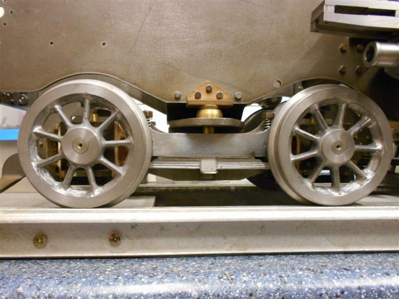 I now need to adjust the guard irons for height, they are fouling the rail at present. Thanks for looking in Steve |
|
|
|
Post by springcrocus on Dec 30, 2015 22:35:31 GMT
Realising that I had yet to complete the pony truck suspension, I decided to get that finished before continuing elsewhere. As with the bogie springs, I will replace these with proper springs at some point in the future but, for now, I will use the supplied castings. There are only a few parts needed to make the suspension - the cast dummy springs, this time in gunmetal, a couple of spring bolts with cross-pins, the spring plunger to carry the coil spring, the spring sockets that rest on top of the springs and the spring guard for over the top of the springs.  The springs were cleaned up top and bottom before putting the hole in them to guide the spring plunger. After drilling 5/16", I ground a spare drill and made the hole flat-bottomed as drawn, but it probably wasn't neccessary. The spring bolts were just some 3/6" mild steel, threaded 2BA at one end and parted off. The drawing calls for 3/32" cross pins but they looked too chunky to me so I used 1/16" material - panel pins, actually - and I made a simple drill jig from some spare hex bar to help put the cross-holes in. The spring plungers were made from 5/16" brass, drilled to accept the coil spring and parted off at 5/8", the spring guard was made from some offcuts of 24 swg brass sheet and the spring sockets were made by drilling a 4.9mm hole through a length of 3/8" square mild steel and parting off at 3/16" long followed by milling on the side chamfers with the Cowells. I also put two together in the small milling vice and drilled a 1.9mm hole to produce the recess for the cross-pins and then linished the underside of each so that they sat nicely on the springs. 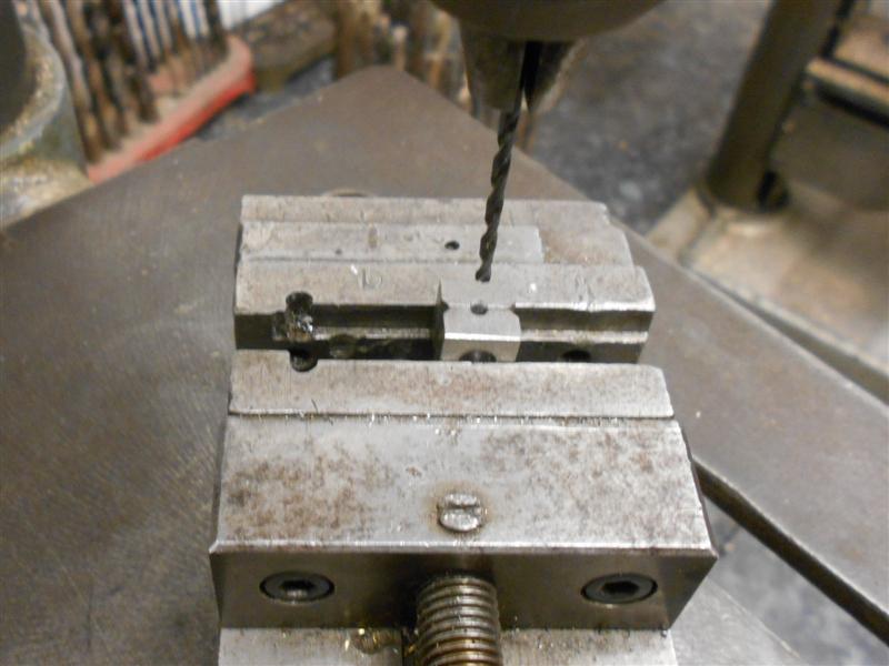 Then it was all bolted together.  The pony truck is now finished (apart from re-glueing the timken cover) and awaiting a really good clean-up and painting, a job for next season. There will now be a short intermission.... I'm taking a break from the workshop for a couple of months or so and, consequently, there won't be any more updates to the diary until about Easter. I have neglected my railway layout in the loft for far too long and am going to concentrate on that for a while. I shall still look in here daily, and contribute if I have anything of worth to post, but many may breathe a sigh of relief. Thanks for looking in, Steve |
|
|
|
Post by Deleted on Dec 30, 2015 23:17:32 GMT
looking good Steve...don't be away too long...now then...'railway layout in the loft'?...do tell more, scale, period etc...I would like to do a layout myself one day, I used to have one many years ago after my late grandfather introduced me to the hobby with his mainly LNER collection in 00 gauge...I plan on doing a layout in 'O' and have made a few items, loco, brake van and a turnout, plus a few other bits awaiting my attention, all LNER naturally..the loft is already clear although I think it's going to be a long time before/if I ever get around to it...
Pete
|
|
|
|
Post by Jim on Dec 31, 2015 3:25:58 GMT
Hi Steve, I'm sure photos of your layout in the loft would be welcomed.
Jim.
|
|
johnthepump
Part of the e-furniture
 Building 7 1/4"G Edward Thomas
Posts: 494 
|
Post by johnthepump on Dec 31, 2015 23:54:46 GMT
Hi Steve, Just as you have got your new mill set up, your away to the loft to do another project. I hope your loft is insulated as the weather is on the turn. I took some of my old clockwork train set out of the box in the loft and put them in the workshop many years ago, " The train on the crane"  |
|
|
|
Post by springcrocus on Jan 1, 2016 11:19:24 GMT
I thought I would add one last picture (well, two actually as a composite) to show where the build has progressed to before I put a cover over it.  Back around Easter, and thanks for looking in. Steve |
|
|
|
Post by springcrocus on Mar 26, 2016 19:15:22 GMT
After a couple of months concentrating on other interests, I thought it about time I returned to the workshop and get Britannia moving again. I have chosen to make my cylinders from the cast iron casting that are available although I could have chosen gunmetal cylinder castings or raw material of either type. I will also be using cast iron pistons and cast iron rings. The castings were a reasonably good shape and I didn't see any chilled spots although I wouldn't have expected to with lumps this size, and with no small protuberances which are the usual casualties. The first job I did was to load them to the independant four-jaw chuck on the lathe and clean up the ends. If there were any chilled spots, my lathe tooling is more substantial and better able to cut through them. I wasn't trying to get anything accurate machined here, just to get a couple of flat surfaces to help subsequent operations.  They weren't coming off the lathe anything like square so it was over to the milling machine and loading to an angle plate, getting the casting reasonably square to the table and then cleaning these faces up again. Again, I wasn't after anything accurate here, just a starting point for clamping purposes. I used my large flycutter for this, 4" diameter with a carbide cutting tip rotating at about 400 rpm.  Once I was happy that the ends were reasonably square, I then machined the back, clamping to the angle plate through the two rough bores and removing enough material to just clean up.  These were now measured and checked properly for squareness and centre-ing which showed there was still about an eighth of an inch still to come off the length. To reduce the overall length, I opted to hold them a little differently, using my independant 4-jaw chuck mounted to the table, adjusting how much I took off each end to get them balanced. 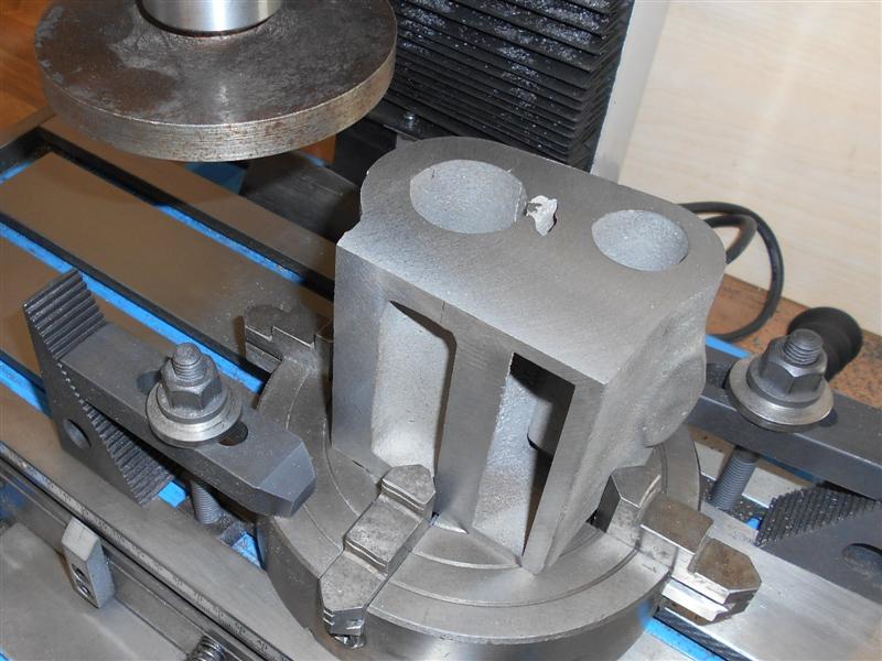 The drawing shows that the centrelines of the cylinder and the valve bores are offset 7/16" from each other in the vertical plane but a close look at the castings revealed that the core for the valve bore is set about 1/16" too close to the front of the casting so I have made the offset 1/2" which will allow the cylinder core to be machined reasonably evenly and the valve core will lose 3/16" at the back and 1/16" at then front to bring them back to the 7/16" offset. I set them up as shown below. 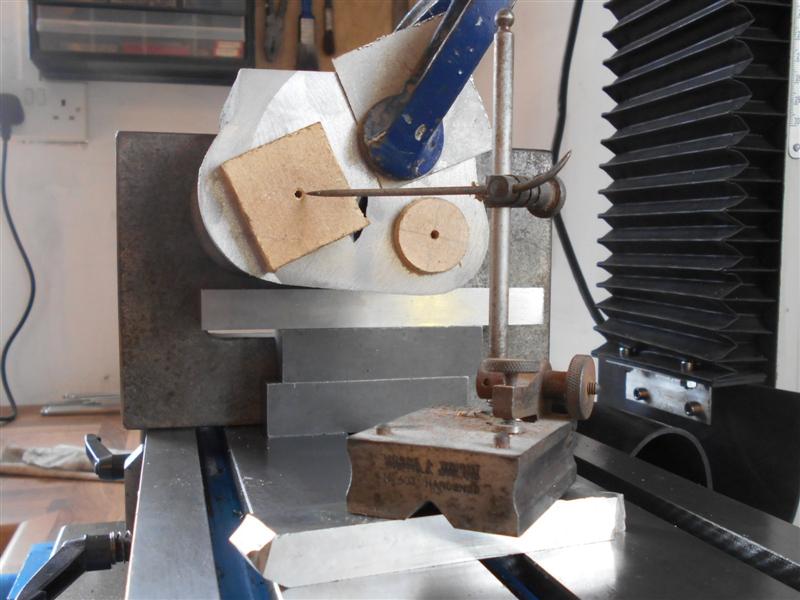 The plugs are small pieces of MDF wedged in and centered so that I could eyeball the amount of tilt required. After setting the scribing block to the centre of the valve bore, I set it on a piece of 1/2" tool steel and adjusted the casting to set the centre of the cylinder. Then it was bolted up, the clamp removed and the back faced off again until I had a full clean-up.  I shall rough out the bores before coming back and finishing the backs and then finish the bores in the traditional way, but that's for next time. Thanks for looking in. Steve |
|
stan
Seasoned Member

Posts: 110 
|
Post by stan on Mar 26, 2016 22:27:22 GMT
Don't think that because they are big castings that you don't get any hard spots, mine bought from Norman Spink for my 9F were full of them even had problems drilling and tapping 10BA for cleading. Yours certainly look good , keep up the good work.
Stan
|
|
|
|
Post by Jim on Mar 27, 2016 2:43:11 GMT
...and my bronze castings had blow holes which led me to fitting liners. There's always something that spoils your fun isn't there?
Seriously Steve, your work is looking brilliant and a very fine model is well on its way. Looking forward to you next post, with pics of course.
Jim
|
|
|
|
Post by springcrocus on Mar 27, 2016 6:38:10 GMT
Stan and Jim, thanks for your comments, I won't hit the "like" button for either of you, it doesn't seem right somehow. A "sympathise" button would be more appropriate. Which reminds me, special thanks to Reg (RGR60130) who had these cylinders amongst his surplus castings and let me have them at a generous discount. You were concerned, Reg, that they might be chilled in places but I'm happy to report that they are very free-machining. And, like Jim, if there are any blow-holes when I bore them out, I will just sleeve them, no big deal. I won't be moving forward with these for a while, I am waiting for my new DRO for the mill to arrive and am deliberately avoiding any jobs where it would pay dividends to have the DRO set up. Its somewhere between Hong Kong and Southampton at the moment. And I need a faceplate for my lathe or I might be heading, cap in hand, to the Pumphouse.  Steve |
|
|
|
Post by springcrocus on May 27, 2016 18:07:29 GMT
It's been a while since I updated the diary but most of my efforts have been on preparation or covered in sub-topics. Anyway, more work has now been done on the cylinders. I described how I converted my compound slide for use in the vertical plane HERE and, once I had proof of principle, it was time to load the cylinders to the lathe and make some more swarf. First thing I did was to go back to the earlier ops and get the overall length finished to size and to get the centreline of the piston bore reasonably accurate to the back face. These were just repeats of the earlier machining. Then I drilled all the bolt holes on the back of the cylinders but I've also added a couple of extra holes that are not on the drawing. These have been reamed 3mm and I have also modified the mounting plate by drilling and reaming two holes and setting 3mm dowels into them.  Although I am going to finish the bores using a between-centres boring bar, it's a lot of work because these bores have a lot of meat in them. Therefore I set up to rough machine the two bores and had to make a holder to carry the boring bar to enable me to load it to the 4-jaw independant chuck.  Here, I've loaded up the first cylinder and set the centre of the bore before locking the slide in the first direction and taking the gib screws up pretty tight in the other. Then it was just a case of feeding through under power, backing out, adjusting the bar and go again.  However, after the first few passes on the first cylinder, it became obvious that the setup wasn't quite rigid enough so I stopped machining and modified the lower clamp by bolting on a block with an M10 bolt through it. Once I had clamped the cylinder up again, I then adjusted this bolt down onto the slideway with just slight pressure and a piece of brass packing beneath and this took practically all the spring out of the fixture.   And this is where the dowels came in useful. I was able to machine the largest bore on the first cylinder, unbolt it and load the second cylinder and be confident that the two bores were in the same place relative to the casting. Now I will use the same boring bar to rough out the valve bore before setting up for between-centres boring to finished size. Thanks for looking in Steve |
|
|
|
Post by springcrocus on Jun 13, 2016 7:00:12 GMT
I have now completed machining the cylinder castings with the exception of honing the bores to size but have not yet decided how I will approach this. Because I put a pair of locating dowels in my mounting plate, I was able to get everything clocked true and then load each cylinder in turn and continue with between-centres boring getting each bore to about ten thou undersize and then setting the boring bar to final size and finishing each bore in turn. I have left all the bores three thou undersize to allow for honing, which should be ample, but it won't matter if they need a bit more. The valve liners and pistons will be made to suit.  I was able to measure them in situ without removing the boring bar using a dial caliper gauge but forgot to take a picture at the time. Here is a picture taken later showing the type of clock I am referring to. They are very good comparator gauges and I have modified this one slightly with some pressed-on stainless steel feet. I set the size using a 1" - 2" micrometer.  To drill the various holes, I took full advantage of the new DRO and used co-ordinate positioning throughout. Each cylinder casting was squared up on the mill and the centre of the main bore accurately found using a wobbler. Using the tables in the Zeus book for a twelve-hole setup, I worked out the X and Y co-ordinates of each hole and worked my way round centre-drilling and then drilling 3.0mm diameter. If anyone is unsure about this method, there is a reference to calculating hole positions in a short article HERE that I penned some time ago.  The draincock holes were also drilled and tapped 1/4" x 40 and the final work on the mill was to mill the steam port and drill and tap the holes. The drawing shows that the face of the steam port is 27.5 o to the horizontal and recommends drilling the steam inlet hole after assembly of the valve liners. Using angle gauges, I set mine to 27 o and milled the face flat with an endmill.  I also drilled the 4BA stud holes and the 5/16" dia steam hole at this stage and will drill through again after assembly. The cast pads were not exactly in the centre of the castings which is down to me for not getting equal amounts off of each end of the casting during the facing operations. However, I have made sure that the holes are central to the machined end faces.  Finally, all seventy-eight holes were tapped freehand using a 4BA spiral point tap (except the draincock holes, of course) and I am relieved that all went well. To break a tap at the last moment would be disappointing to say the least. These will now be put to one side while I decide about honing (an invite for other to suggest the best way forward) and will make a start on the con rods. Thanks for looking in, Steve |
|
|
|
Post by Jim on Jun 13, 2016 7:06:42 GMT
That's a big job beautifully done, goodonya Steve you should feel very happy with the work so far.
Jim
|
|
|
|
Post by springcrocus on Jun 26, 2016 7:45:39 GMT
I cut the cylinder backplates out a while ago using some 10 swg mild steel plate, offcuts of the frames material, and had marked out and drilled them. I have now countersunk the holes and screwed a few of the 4BA screws into place but one or two of the holes are not as accurate as I would have liked. These were made before I had co-ordinate drilling facilities whereas the cylinders were drilled using the DRO. I've opened the lower row of holes out an extra four thou and the screws are now pulling in, but I may remake these plates as there is not a lot of work involved.  One advantage would be that I can get the dowel holes that I have added to the cylinder in the correct place. Thanks for looking in, Steve |
|
|
|
Post by springcrocus on Jul 2, 2016 15:57:31 GMT
The left-hand expansion link bracket, like it's counterpart on the other side, looks quite a complicated assembly at first glance. However, once you get started, it's not so daunting. I am using the available gunmetal castings and they really are the pits with loads of material to come off in some places, not much in others and one part of the profile that can't be made as per drawing although it doesn't matter. They only faintly resemble the full-size article and there are fabrications available which are much more like the real thing.  They also require a packing piece to be made that fits between the bracket and the frames because there is not enough material on the casting. It appears that the designer got his sums wrong and no-one has ever bothered to have the pattern modified. I shall be using offcuts of the frame material, 3mm mild steel, and need to account for this in the measurements. Before cutting any metal, the first thing I did was to roughly measure from the as-cast back face to the centre of the reversing screw bosses to get some idea of how much needed to come off the back. I've set the height gauge for 2.065" and it looks like there's about twenty thou to come off the back 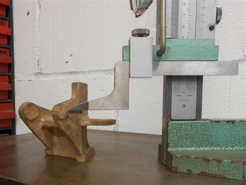 I then checked from the centre of the expansion link bearing to the top and bottom edges of the casting and it appears that the bottom edge needs just a clean-up (with the nib removed, of course) and can then become the starting datum. Holding the casting for the first machining took a bit of thought but I found a way and then milled the back face flat, and also cleaned up the angled edge at the same time. I expected it to sing like a canary when milling the outer reaches but it was suprisingly quiet and no evident chatter.  Now that I had a flat back face, the bottom edge was the next to be machined, followed by rotating round the fixture and milling the other two edges. The next picture shows how I quickly align the fixture using tee-slot packers and parallels when I don't need clocked-out accuracy. The casting was positioned using a scribing block to set the centres of the two reversing screw bosses at the same level for the first edge, and then a square used against this edge for the next one. 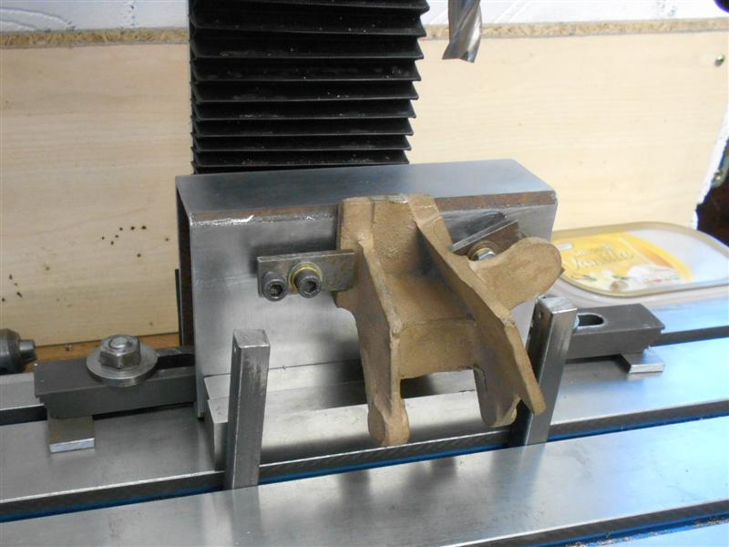 As each edge was machined, the flange thickness was also reduced to 0.200" at the same. This is not a dimensioned item on the drawing but they just about clean up at this size. It gives a flat seat for the lower mounting bolts and make it easier for clamping.  Whilst machining the angled side, I also machined the area where the expansion link bearings go; one is cast in situ and the other gets bolted on later. Although there is a sacrificial piece at the outer edge, the pressure of the cut was bending the casting slightly so I propped it up with a wedge. The pieces at the bottom are a pair of wedges that I made as a ball-joint splitter about forty years ago, nice to see that they still come in useful. The clamps on the table are to stop the wedges drifting loose with the vibration of the cut.  Next up was the insides of the reversing shaft bosses where the left-hand side, or front of loco, gets machined away completely. These were machined to the finished size of 1.5/8" and the outside of the right-hand boss was also machined to 3/8". The top of the weighshaft panel was cleaned up at the same time.  I decided to do the centre section where the weighshaft bush goes next and opted to do a full clean-up rather than the spot-face shown on the drawing. This provides me with a mounting face when I come to drill and tap the fixing bolt-holes on the back of the casting.  The rest of the faces were cleaned up in a similar fashion, just re-clamping in various modes to suit and I shall skip over these operations. The last two pictures show the clamping arrangement for drilling the back. The drawing says "Mark off from frame" but I've calculated where to put the first hole and used the frame drawing dimensions for spacing.   Thanks for looking in, Steve |
|