|
|
Post by Cro on Jul 27, 2017 7:09:26 GMT
Steve, I wouldn't worry about either treatment or having things removable. When I soldered up the 9f tender (baring in mind it was a winson kit and hardly fitted together) it was all soft soldered and with some care it all went together fine and it is bottle tight. I have 4 locos with brass tenders/tanks all soft soldered and not a problem with any of them. Good wash out now and then and they are good to go! But your new filter boxes will protect you from any rubbish anyway  Looking great though, can't wait to see it in the flesh. Adam |
|
|
|
Post by Geoff (Carlisle) on Jul 27, 2017 9:44:16 GMT
Hi Steve, there is only one thing wrong with your tank lid, you should have made two and sent one to me, only joking. Brilliant work.
Geoff (Carlisle).
|
|
|
|
Post by Jim on Jul 27, 2017 9:49:36 GMT
Make it three Steve, can't let that cheeky Geoff get one up on me.  Jim. |
|
johnthepump
Part of the e-furniture
 Building 7 1/4"G Edward Thomas
Posts: 494 
|
Post by johnthepump on Jul 27, 2017 12:59:25 GMT
Hi Steve,
Nice to see you in the Pumphouse this lunchtime, calling in for a chat as you were passing.
John.
|
|
|
|
Post by springcrocus on Jul 27, 2017 13:27:09 GMT
Steve, I wouldn't worry about either treatment or having things removable. When I soldered up the 9f tender (baring in mind it was a winson kit and hardly fitted together) it was all soft soldered and with some care it all went together fine and it is bottle tight. I have 4 locos with brass tenders/tanks all soft soldered and not a problem with any of them. Good wash out now and then and they are good to go! But your new filter boxes will protect you from any rubbish anyway  Looking great though, can't wait to see it in the flesh. Adam Thanks, Adam, that quite reassuring. I've not done enough heavy-duty soldering to be fully confident of my abilities yet, and I asked JtP what he thought when I popped in the Pumphouse earlier and he agreed with you. Note to self - don't get paranoid! Geoff and Jim, I'd love to make an extra pair of tank lids but I seem to have run out of material.   Regards, Steve |
|
|
|
Post by Jim on Jul 27, 2017 22:54:42 GMT
...... 'run out of material!' what a poor excuse. I suppose then we'll have to make our own now Geoff.  |
|
|
|
Post by springcrocus on Jul 29, 2017 18:24:40 GMT
The last work to have been done on the tender front panel was cutting out the triangular cutouts below the scoop and handbrake handles. I have now "ironed on" the two brass shimstock panels just above these and I will set with some 3/64" rivets to mimic the retaining screws seen in the photo. The holes for the brake and scoop handles were also drilled. 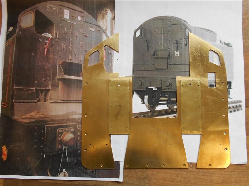 The bosses were made from 3/8" dia brass bar turned to about 1/4" dia to better represent the full-size item and with a 6BA thread on the other end for fixing to the front plate. The handles are from 2.5mm brass rod. 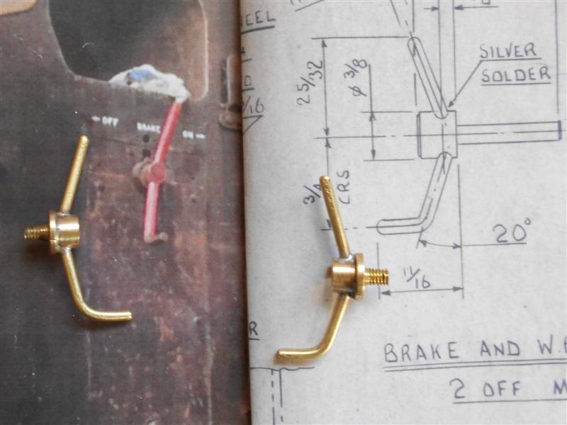 These handles are dummies and will never be turned so the shoulder represents the boss on the bulkhead. The only thing that was less than straightforward was drilling the handle holes at twenty degrees and this was achieved with a simple drill jig to steady the drill. 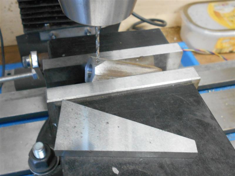 The box section below the coal plate has been made from a piece of 16 swg brass sheet soldered to a pair of 3/8" wide x 1/8" thick brass strip and held on the front panel with 6BA screws from behind. The 6BA holes were drilled and tapped before soldering together and the mounting holes in the front plate drilled to suit.  I decided to have a try at forming the water gauge using a punch and die arrangement. The drawing shows the radius of the gauge face as 1" and set into the front panel with a raised rim. Jim's photo, however, shows the gauge set behind the front panel so this is what I have tried to create. I started by cleaning up the end of a piece of 1.1/4" square bar on the mill and then cutting a recess into the end using a slitting saw, making multiple entries at 1mm height intervals. To make the punch, I turned a piece of flat bar to 1/16" less than the diameter of the slitting saw. Then I cut a piece of 26 swg brass sheet about an inch square, put it on top of the die and gave the punch a whack. As can be seen, the first effort was less than successful, practically chopping the middle out.  I then rounded off the edges of the punch and cut a new piece of material from 24 swg instead. This was more successful and a little tapping of edges soon had it looking reasonable. I cut a slot in the front using a junior hacksaw and made a tiny indicator from some six thou shimstock, folding it round, soldering together and cutting the shape with a tiny chisel.  All these parts were then fixed to the front panel. The coal dust deflection plate has also been made and fitted but is as per drawing rather than prototype. Locker doors next.  Thanks for looking in, Steve |
|
|
|
Post by springcrocus on Aug 3, 2017 18:15:31 GMT
I have chosen to make the locker doors as a cosmetic feature only, and all the parts are made from brass shimstock of varying thicknesses and soldered in place. Once painted, the edges will blend in and should be a reasonable representation of the prototype. The top locker doors and the coal-access doors are on the centre removable section, as are the lamp iron and the top rainstrip. I started by cutting from four thou shimstock, with scissors, the door sections and these were shown earlier laid out on the panels.  These sections were tinned, as was the front panel where appropriate, and the two brought together with another layer of flux. The front panel was set over two blocks with a weight on top of the door panel and heat applied from below. This took a while because of getting the weight up to temperature but it stopped the shimstock rippling from expansion and everything was left to cool naturally. To make the dummy hinges, I cut some 3/8" square sections and dimpled them with a centre punch then tinned them.  They were turned over and a length of 1mm dia wire soldered on to represent the hinge pin. A tiny dab of flux was placed where the hinges go and the hinges held in place with a brazing finger while heat was applied. For this, I used a micro torch which runs on butane lighter fuel because it produces a tiny but very hot flame and gets local heat in without lifting the door panels too much.  The locking bars are held with a 3/64" rivet and the catch plates are soldered on. I did the lower section first and then the upper section.  It looks a bit scruffy at the moment because of the solder being a different colour but I think once it has a coat of primer, all should be well.  I've also added a rainstrip over the centre locker but this is probably as far as I will go regarding detail except the lamp iron which I forgot to do. I've screwed the front panel back on to the tender and reassembled the lift-out panel to check that it still fits OK. For some reason, the colour looks very washed out.  And finally an overview picture showing progress to date. There's not much left to do now, beading round the bunker, dummy coal tray and solder the bunker into place. 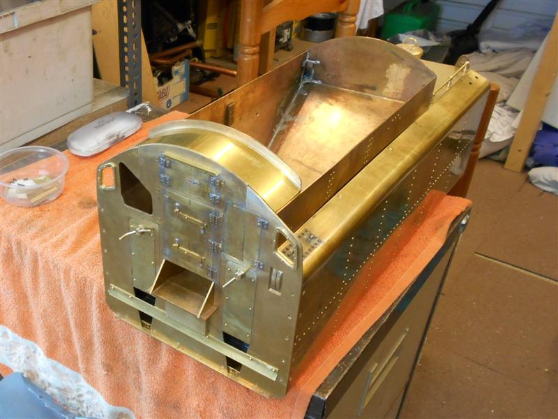 After trying this method of fixing the doors, which would normally be flush to the front panel, I hesitate to recommend it as a means of achieving a reasonable appearance without cutting everything out and refixing. It's been an interesting exercise but frustrating at times when panels started to lift, difficulty getting localised heat etc. No regrets, but a different approach next time, methinks. Thanks for looking in, Steve |
|
|
|
Post by Deleted on Aug 3, 2017 18:18:10 GMT
Very nice Steve, the tender is looking great sir...
Pete
|
|
|
|
Post by Jim on Aug 3, 2017 21:55:52 GMT
Your BR1 tender is certainly looking great Steve. Won't be long now before you have it completed and coupled up behind the loco ready for your first run.
Jim
|
|
|
|
Post by 92220 on Aug 4, 2017 9:10:28 GMT
Nice job Steve. Very nice! It's looking good! Keep the photos coming. We can all learn from other's ways of achieving results.
Bob.
|
|
jools
E-xcellent poster
  
Posts: 200
|
Post by jools on Aug 8, 2017 1:46:28 GMT
Hi Steve
what a brilliantly "riveting" diary for a novice such as myself. Your tips and techniques are invaluable and have unlocked the mystery of the sub assemblies, what they do and how they fit together.
Its made the tasks ahead seem less daunting, and I have been adding to the list of required tooling I will be needing. The first purchase being a DRO for my Sieg SX3 milling machine (ordered)
Although I am only in the planning stage of a DY Black 5 in 5", the recently acquired plans are being redrawn in AutoCAD in Imperial decimal which will then be printed into sub assemblies on A3 sheets where possible.
I look forward to more of this build and thank you for sharing with us all.
|
|
waggy
Statesman
 
Posts: 747
|
Post by waggy on Aug 8, 2017 7:25:50 GMT
Good morning Steve,
Methinks this tip a bit late to help you out but hey ho!
If you use an automatic type centre punch, you can set the tension so all the dimples come our exactly the same size. I was told about this by a chap who builds 00 gauge stock, it works well.
The punch I refer to is the spring loaded type as here from the Kennedy Web page...KEN5181710K
Regards,
Waggy.
|
|
|
|
Post by Roger on Aug 8, 2017 7:27:50 GMT
Hi Steve what a brilliantly "riveting" diary for a novice such as myself. Your tips and techniques are invaluable and have unlocked the mystery of the sub assemblies, what they do and how they fit together. Its made the tasks ahead seem less daunting, and I have been adding to the list of required tooling I will be needing. The first purchase being a DRO for my Sieg SX3 milling machine (ordered) Although I am only in the planning stage of a DY Black 5 in 5", the recently acquired plans are being redrawn in AutoCAD in Imperial decimal which will then be printed into sub assemblies on A3 sheets where possible. I look forward to more of this build and thank you for sharing with us all. Hi Jools, There's great stuff in there for all of us, even if we've been in Engineering all our lives. One valuable lesson Steve makes clear is that there's no right way to do a particular job. His solutions are a good fit for the machines, tools and anything else that can be pressed into service to achieve the desired goal. Everyone's kit is different, so the solutions are likely to be different too. When you come to make your Black 5, this thread will be of immense value, but you will develop your own lateral thinking to make the most of what you have, particularly when it comes to holding things for machining. I hope you'll share it on a build thread, warts and all, so we can all learn together. Mistakes and ways you get caught out are every bit as valuable as the things that go swimmingly well. |
|
|
|
Post by springcrocus on Aug 8, 2017 11:27:34 GMT
Good morning Steve, Methinks this tip a bit late to help you out but hey ho! If you use an automatic type centre punch, you can set the tension so all the dimples come our exactly the same size. I was told about this by a chap who builds 00 gauge stock, it works well. The punch I refer to is the spring loaded type as here from the Kennedy Web page...KEN5181710K Regards, Waggy. Thanks for that, Waggy. And I'm a silly fool because I actually have a spring-loaded punch and didn't think to use use it.  Never stop learning, do we? Regards, Steve |
|
|
|
Post by springcrocus on Aug 8, 2017 11:35:29 GMT
Thanks for the comments, Jools.
As Roger says, we all approach jobs differently depending on the tools avaiable, the confidence one has in their abilities and what we are trying to achieve. I try to present my work in such a way as to show that there are alternatives to the traditional ways. Sometimes I get it wrong but the trick is to learn and move on.
This hobby has never been rocket science but I try to keep things as simple as possible. The first step to making the pefect model, which anyone can achieve, is to pick the tools up and have a go.
Regards, Steve
|
|
jools
E-xcellent poster
  
Posts: 200
|
Post by jools on Aug 8, 2017 20:24:25 GMT
Thanks for the comments, Jools. As Roger says, we all approach jobs differently depending on the tools avaiable, the confidence one has in their abilities and what we are trying to achieve. I try to present my work in such a way as to show that there are alternatives to the traditional ways. Sometimes I get it wrong but the trick is to learn and move on. This hobby has never been rocket science but I try to keep things as simple as possible. The first step to making the pefect model, which anyone can achieve, is to pick the tools up and have a go. Regards, Steve You have certainly met your criteria, I was beginning to doubt my ability to picture how best to approach a build until I read this and I'm sure when I eventually go through other threads there be other snippets that get locked away for reference. Now I can't wait to get stuck in LOL! |
|
|
|
Post by springcrocus on Aug 12, 2017 21:37:13 GMT
I made the tender chassis a couple of years back and have now stripped it back to the component parts in preparation for painting. I am, however, adding a few extra details that are not on the Warnett drawings including extra dummy rivets. The tender frames have been made from guillotined pieces of 3mm mild steel plate and were marked out by hand and all the cutaways made with hacksaw and files. Because I didn't have my larger mill at the time, all the holes have also been marked out by hand or spotted through the various components. The half-ovals were chain-drilled first, followed by removing with a cold chisel and filing the shape to finish, and the large hole at the rear of the frames was made using a hole saw.  Because most things are dimensioned to fit inside the frames, I kept these dimensions and compensated for the thinner frame material (two lots of seven thou) by making the horns a little wider. Looking at photos of the prototype, there is a row of rivets that appears to run the full length of each frame just below the sole plate. By counting rivets between the spring hangers, and using the drawing dimensions between hangers, I was able to calculate the spacing. The photo, a thumbnail created from the Fraser Kerr collection, shows the bracket between the centre spring hangers and the rivets for the stretcher.  The frames were set up on the mill and a series of 1/16" holes drilled between the water filter and the rear steps. The water feed pipe hides any rivets that may be towards the front and have not been drilled.  A further detail I have chosen to incorporate are the rivets for the rearmost top frame stretcher which is a series of twelve holes, also in 1/16". The front stretcher is behind the filter box so wouldn't be seen and not worth copying. The final detail I have added is the triangular-shaped bracket directly above the centre spring and is cosmetic only. 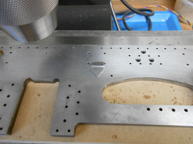 After removing from the mill, all the holes were countersunk on the rear. The dummy rivets were then fitted and hammered flat at the back, followed by dressing back to flush, particularly in the area of the top stretchers. The triangular brackets were also fixed and the frames are now ready for priming.  Thanks for looking in, Steve |
|
|
|
Post by springcrocus on Aug 15, 2017 18:32:31 GMT
The drawing shows the leading beam as a two-part assembly with 1" x 1/2" x 1/16" channel behind the buffer plate, riveted together. I had a short length of 1" x 10swg box section available and made my own channel from this, whilst the buffer plate was cut from 3mm mild steel sheet. The drawing also calls for the frame-mounting plates to be silver soldered to the ends of the channel but I felt that some form of mechanical fixing was also required and made a pair of angles to fit in the ends of the channel and riveted to the buffer plate. I started by sawing the box section longways to produce the channel, dressing the sawn edges and milling the ends square and to finish length. The two angle pieces for the ends of the channel were cut from the waste and the holes for the rivets marked out and drilled. Next, I marked out and drilled the twelve rivet holes in the front plate, countersinking quite deep, and all the bolt holes for the bufferstocks and the pivot block. On the channel, I marked out one rivet hole at each end and then riveted all the parts together, remembering to include the angles. Now, it was easy to hold the channel in a machine vice and spot through all the other rivet holes, finishing off by setting all the rivets and filing the front face flush. They can just be seen in the photo although this was taken later because I hadn't put the larger holes in at this stage. All the other small holes were drilled through at this stage also. 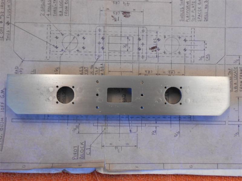 The bufferstock location holes were made next, followed by the drawbar slot which I stitch-drilled and chopped out, then filed to size. I didn't have my larger mill then or I would have cut the hole with a small slot drill. All the holes that needed threads were done at this stage and care was taken with the pivot block holes as four of them foul the channel behind. The reason for this is because the pivot block on the loco has the mounting holes in a different position to the tender but I had made mine both the same and had to modify the tender dimensions to suit.  The end plates were made from offcuts of the 3mm mild steel sheet. The two forward holes were drilled 6BA clear and the four rearward holes drilled and tapped 6BA. After drilling and tapping the angled ends of the channel, I was able to bolt the end plates on prior to soldering. The two front screws go through the frames and the end plates, screwing to the riveted angle pieces, thus providing my mechanical fixing.  These are now ready for priming. Thanks for looking in, Steve |
|
|
|
Post by springcrocus on Aug 19, 2017 18:21:23 GMT
The buffer housings on the leading beam of the tender are drawn as a fabrication silver-soldered together but I found it easier to make mine from solid. There is little need for accuracy required here other than a nice sliding fit of the buffer in the tube. Because my 3-jaw chuck accepts 1.3/16" dia material in the bore I cut a 4.3/8" length of EN1A, enough for two housing plus parting and facing. With half of the material hanging out of the chuck, I faced off the bar and then turned the O/D down to 0.650" for the 2" length shown. 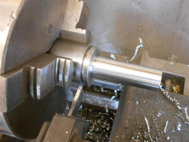 The bar was then reversed in the chuck, shoulder up against the jaw face and the operations repeated, folowed by parting into two components. Leaving the first one in the chuck, I drilled a 31/64" diameter hole to within 1/8" of the bottom, taking advantage of the flange to prevent the material moving. The hole was then reamed 1/2" diameter as deep as possible and the front faced to leave a flange thickness of 1/16". This was repeated for the second one.  A small chuck was set up on the table of the Cowells to enable machining of the square flanges, setting the centre as the zero datum and milling an equal distance out from centre for each side. The four mounting holes were centre-drilled at the same time but drilling was done free-hand on the pillar drill as the Cowells doesn't have the headroom for drilling. As you can see, it's a bit cramped on the mill table.  The corner radii were done freehand on the linisher and with files. The retaining slot was made by holding the workpiece in a small machine vice and milling with a 1/8" diameter slot drill. The retaining pin is yet to be made. The plungers, or buffers, were made from 1/2" diameter EN1A. The hole for the spring was drilled first and the O/D polished with emery to give a nice sliding fit in the buffer housing. They were than reversed in the chuck and the front form created by turning the shoulder and using a form tool to create the radius.  Thanks for looking in, Steve |
|