|
|
Post by Geoff (Carlisle) on Aug 19, 2017 19:27:22 GMT
Hi Steve, looking at your photo of the spring brackets, well I've still got the castings for these but decided to make them as they are. I suppose the real ones were castings but i'm fabricating mine and i'm pissed off. There are six piece's of steel of which four are silver soldered together. The other two are a small brass cushion underneath and the front plate which is screwed on with three 10BA hex bolts. I've only made six up to now and still another six to make which can take a whole afternoon to make one, then they have to be sand blasted afterwards. If I were doing it again I would go for the castings. I read all yours with great interest.
Geoff (Carlisle).
|
|
|
|
Post by springcrocus on Aug 23, 2017 17:39:24 GMT
The pivot block was covered earlier in the diary as part of the loco rear beam but is included here for completeness. For anyone making Britannia to this set of plans, the mounting holes are different on the loco compared to the tender and causes a problem if made to the loco dimensions. The central stand-off bracket, or pivot block, is a fairly rough gunmetal casting and a little thought went into the machining sequence. Because the casting sprues were so prominent, I decided to mount the pivot block on a small angle plate, setting the side square to the table, and milled the top edge with my small flycutter until cleaned up.  Now that I had one clean face to work from, all further work was done in the milling vice, starting with the bottom face and then some more off the top to get the webs and drawbar slot balanced.  The next job was to face the back to the nominal size. To get it level, I set four screws into the tender front beam (rear beam of the loco in the picture) and adjusted them to the same height. 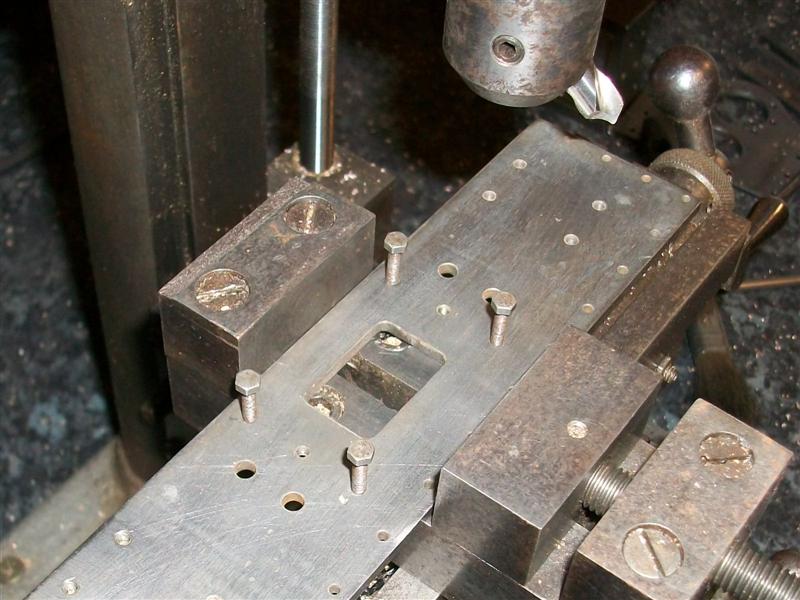 This then went into the bottom of the milling vice and the casting settled on top. The back was then machined with a flycutter. There is no size given on the drawing but scaling from the drawing, which is normally inadvisable, worked out at about 1/8". It wont matter as long as I remember to make the drawbar to suit, not just to drawing.  The sides and the large radius were dressed clean on the linisher - no particular size, just to please the eye - and the mounting holes were marked out and drilled 6BA clearance. To finish off, it was given a quick session in the shot blast cabinet to make a good surface for painting.  Thanks for looking in, Steve |
|
|
|
Post by Roger on Aug 23, 2017 18:41:15 GMT
Hi Steve,
Another great setup with the jacking screws and clamping rod. We were taught to use a round bar for holding that first reference face against the fixed jaw, and it's absolutely ideal for what you're doing. There's something really satisfying about setups like that.
|
|
|
|
Post by Jim on Aug 23, 2017 21:38:58 GMT
Thanks yet again Steve for creating a great visual lesson on how to set up and hold awkward castings for machining.  Jim. |
|
|
|
Post by springcrocus on Aug 27, 2017 19:00:33 GMT
The rear beam has been made in a similar fashion to the front beam, again using a section of 1" x 1/8" box section to create the channel as well as my belt-and-braces angles at the ends of the channel. This time, however, the channel is set level with the top of the buffer plate and the plate is screwed on after other parts have been fixed. Because of this, the angles were fixed in place first, and a very light skim given to the ends to dress them square. 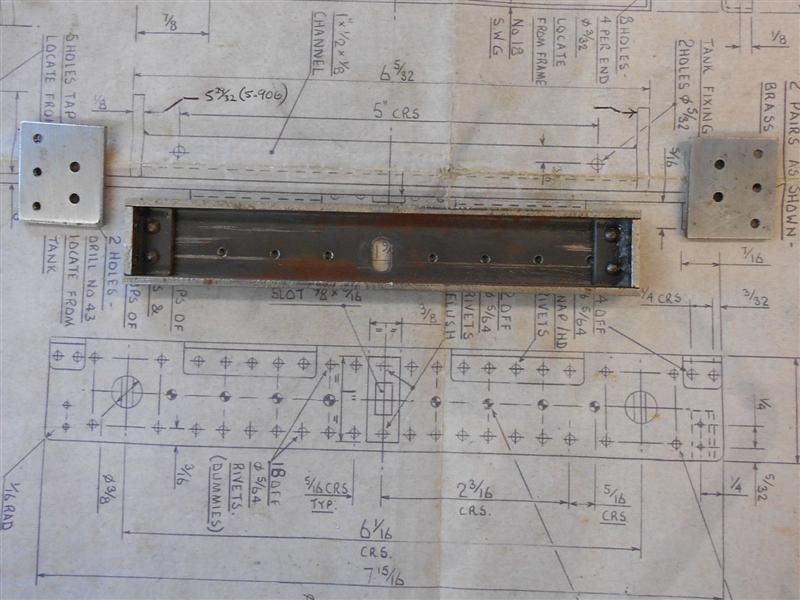 As before, the side plates were made from offcuts of 3mm MS sheet and bolted on before soldering together. All the holes in the plate were marked out, centre-popped and drilled freehand. The brass angle pieces were cut from stock material and drilled also. I fixed all the dummy rivets first, followed by the angles and, finally, the drawhook stregthening plate. The drawing calls for the buffer plate to be riveted to the channel but I have chosen to use 6BA countersunk screws, hence the deep countersinks. The screws will be filled prior to painting.  On the back of the buffer plate, all the rivet holes were countersunk and the rivets have been hammered in and filed flat to enable fixing to the channel. I managed to make a bit of a pig's ear of the buffer stock alignment holes, as can be seen in the picture, having to file them over to get the stocks to bolt on. It's not important, though, just annoying. The screw holes are in the correct position. I am not going to cover the buffers and buffer stocks because I made these on a Colchester Tornado CNC lathe eighteen years ago and there is not much point in describing the process on here even if I could remember it. I do recall that I made the stocks in a single operation from round bar, leaving only the mounting holes and square shape to finish by hand. The buffers were turned and parted off in a single operation, the parting tool being used to get most of the way though, retracted and then following the circular path needed to form the shape, just leaving a small pip to linish off.  Also in the picture is the drawhook which was made completely freehand with a few drilled holes, a hacksaw and files. And then I remembered that the tender buffers cannot be made to work in the same fashion as the loco buffers because the frames clash perfectly with the centreline of the buffers and a different means of retention was required!  Therefore, a 1/8" slot was milled in the underside of each stock for a distance of 3/8" and a 3mm threaded peg made that screwed into the buffer after assembly, in the same manner as the tender-to-loco buffers. Thanks for looking in, Steve |
|
|
|
Post by springcrocus on Aug 29, 2017 7:07:07 GMT
The bank holiday weekend has given me a chance to crack on with the cleaning and priming of the components of the tender frames and I'm getting close to re-assembly. Some more of the parts described here. The drawing shows the two bottom stretchers as a fabrication, made from 18 swg mild steel, but I have chosen to make mine from solid. The drawing also shows them riveted into position but I am going to fit mine with 8BA screws instead. To be any use, these need the length to be reasonably accurate and I don't feel I could bend sheet steel to this level of precision. Milling them to length is the obvious answer. Two pieces were first sawn from 40mm x 10mm black steel and these were then cleaned up all round on the mill, finishing at the exterior dimensions as per drawing. Following this, the two circular and one rectangular relief sections were milled away to leave a solid version of the stretchers.Then it was time to pocket mill the interior sections and this was done with a 10mm carbide end mill, twenty thou depth per pass and full-width cutting around the periphery before clearing the centre. All previous work had been done on the little Cowells but I had my larger mill when it came to do this operation.  As can be seen, I have left the side wall thickness nearer to 1/16" rather than the specified 0.048" but the ends are about 1/4" thick to allow for making the fixing holes. When the milling was complete, the stretchers were clamped to an angle plate and the holes drilled and tapped 8BA. Here are the two finished articles ready for painting and assembly.  The top stretchers have been made in a similar fashion to the leading and rear beams by using 1" square box section for the cross-member. However, I made these as a fabricated item requiring no soldering because they are just a spacer. To make the end pieces, I faced a pair of 1.1/2" dia mild steel billets on the lathe, then milled them to the shape shown.  The holes in the ends of the channel were drilled 6BA clear and matching tapped holes put into the blocks, which are a snug fit into the channel. I also drilled the tank mounting bolt holes in the top of the stretchers but had to redo them when I decided to change the position of the tank bolts for ease of manufacture.  Thanks for looking in, Steve |
|
|
|
Post by springcrocus on Aug 31, 2017 14:10:45 GMT
There are castings available for the tender spring hangers but I felt they made an interesting little project to machine from solid bar. Twelve are required and this lends itself nicely to some sort of production-line technique. Material is unimportant and I have chosen to use EN1A mild steel. On the drawing, I measured the minimum dimension needed to make the parts from round bar and it appears that 1.1/16" dia would suffice. I had 1.1/8" dia in stock and twelve billets were cut from this and faced to the given length of 13/16". I have transposed the circle onto the drawing to determine the best way to mill the rectangular shape, and have added dimensions that are either scaled or calculated to help with this. This is the starting shape.  Next, I drilled the four mounting holes, and an extra hole not shown here (explained later), 1/16" dia x 3/16" deep. The billets were then turned over and the three front holes drilled, not as drawn but also 1/16" dia and by 1/4" deep. The holes are for dummy 10BA bolts so can be opened out later and the bolts set with adhesive or tapped with very little effort to give a shallow thread. I didn't fancy having to thread thirty six full-depth holes with all the inherrent risk of tap breakage when it is unneccessary.  Drilling the holes at the start made it easy to do the subsequent milling operations and the first of these was to machine the upper angled faces. I had calculated that I wanted 0.085" from the edge of the holes to the outside, seen on the drawing in the picture above. Using two 1/16" drills, the hangers were set in vice and the cutter just touched on to one of the drills. the DRO on the quill was zeroed, the quill lifted by 85 thou and the DRO re-zeroed. Now I was able to mill the whole of the top profile.  Using a single drill, I then set the hangers at various angles to rough out the radius at the top and these would be finished with a file.  The back of the vice had been set as the "Y0" zero datum and by working down to the "Z0" depth and to the calculated "Y" position each time, there was no need for a workstop on the "X" axis and the rear inner face was blended as work progressed.  Next, I machined the shape of each of the lower sides in turn. I calculated that the angle should be twenty five degrees but I didn't have two holes avaiable to copy the earlier operation so an angle block was used in conjunction with a single locating pin. The workstop is being used to prevent the angle block moving whilst setting the workpiece into the vice but location is unimportant.  Since I'm still using the same cutter, the "Y" dimension stays the same as does the quill setting of zero. Once all twelve were done, the angle block was reversed and the stop moved to the other side of the vice. The other sides were now machined to size.  In a similar manner, the spring housing was cut away next followed by the necking on the sides of the brackets, using 10mm and 6mm dia cutters respectively.  Then it was time to create the lower shaping and this is where the extra hole came in. When I realised what was needed, I went back and drilled the extra hole in all twelve, it needing to be 112 thou up from the base, or 0.763" from the top, and on the centre line. This was drilled 3/16" deep to ensure it didn't break through, but would probably be hidden by the spring if it did, so maybe not too important.  So, once again, I was able to support the work on pins and create the required shape and was also able to take a little off the front section.  Finally, I set a workstop and reloaded them on two pins to enable drilling and tapping of the 6BA spring-mounting holes. From this point on it was all hand-work, filing and linishing the radii.  All that is required now is some time spent polishing them, and fixing the dummy 10BA screws into the three face holes. I have made these to conform with the Warnett drawing but, as Geoff pointed out a while back, they don't look much like the prototype except head-on. However, they could be machined further using the same system by milling away material on top and at the sides to create a more authentic look but that's a detail too far for me. This has been quite long-winded but I was hoping to demonstrate that, by drilling the holes first, all the subsequent operations became so much easier. And when there are twelve to make, this style of manufacture is quite efficient. Thanks for looking in, Steve |
|
|
|
Post by springcrocus on Sept 2, 2017 21:48:45 GMT
Just a short update tonight. The dummy springs should have been gunmetal castings but aluminium ones have been supplied instead. Because of this, I have made a modification to the item by using a brass liner in the spring housing. There was just enough room to drill and ream a 7/16" hole in each and press in the liner. The other parts are as drawn and quite straightforward.  I've cleaned up the area of the buckle and filed the underside of the springs but I'm not particularly impressed by the quality of these castings and may reconsider keeping them once I have seen them painted. Thanks for looking in, Steve |
|
|
|
Post by springcrocus on Sept 5, 2017 6:21:48 GMT
The horn cheek castings come as a pair joined together but I chose to separate mine and machine them separately. There was nothing out of the ordinary in machining these, being held in a machine vice for all operations. The only tip I can offer regarding these is the little clamping piece I made up to help hold the work. With twelve cheeks to do, this came in very useful and easy to use - beats juggling with other forms of blocks or pads.  When I mount the vice on the small Cowells mill table, the fixed jaw is square to the table within a couple of tenths of a thou so I put a double thickness of baking foil under the fixed-jaw end to create a tiny deviation from the vertical for the fixed jaw, such that the finished components were "toe-in" at the outer ends when mounted on the frames. 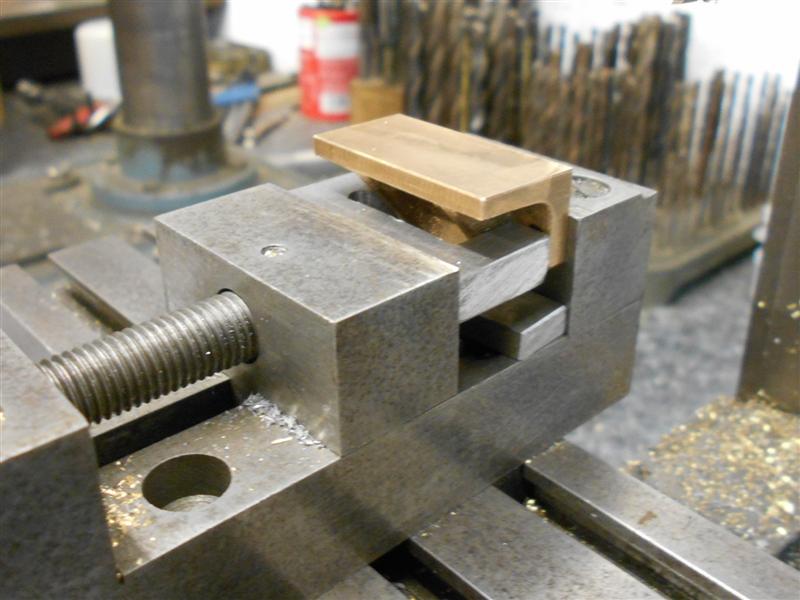 Once all the milling was complete, the holes were drilled and countersunk, and each cheek marked with it's location for strip-down and re-assembly.  It is usual to use rivets to fix the horn cheeks in place and then final machine but I have fixed mine with cheats rivets - 8BA dome-head screws without slots. This gave me the opportunity to adjust the cheeks using a 1.1/4" square bar and feeler gauges, without the need to machine them in situ. Once they were screwed firmly into place, two holes were drilled through the frames and into the webs of each cheek and a pair of silver steel dowel pins inserted. This should stop them moving in service since, unlike the main locomotive horns, they are not subjected to a reciprocating action.  Another small modification that I made is evident in the previous picture. Having the larger mill available, I took the opportunity to widen the horn openings in the frames by ten thou per side to ensure that the axle boxes only touched the horn cheeks and not the frames to prevent any possibility of galling at a later date - my axle boxes are made from mild steel. A final polish with some emery cloth on a stick (parallel for the purist) was enough to dress the outer ends of the cheeks and create the small amount of clearance needed to allow the axle assemblies to move up and down smoothly. The horn stays were made from some 1/4" square mild steel, cut to length and the rear milled away to create the required shape. Although not shown on the drawing, I have also milled the fluting that is evident on photos of the prototype using a small Woodruff cutter. A pair of tapped holes were put into an offcut of mild steel sheet to allow bolting of the components prior to machining.   Now it's time to do some more priming. Thanks for looking in, Steve |
|
|
|
Post by springcrocus on Sept 7, 2017 18:28:27 GMT
The area behind the leading beam is taken up by a strange ensemble of plates and spacers that provide fixing points for the drawbar pin supports, the brake and scoop bellcrank assemblies and also the upper platform and deflection plate. The first of these is the top plate, made from 16 swg brass sheet, which sits between the frames and flush with the top. Soldered to the underside of this is the upper drawbar pin support, made from 1/2" dia brass bar. The hardest part of this component is deciphering which of the mish-mash of dimensions on the drawing relate to this and which to the lower plates.  After making each of the items as per drawing I found it very awkward to assemble the parts, wishing for a second pair of hands. Subsequently, I made a couple of modifications to make life easier. The first of these was to discard the lower front spacer in favour of three brass bushes soldered to the underside of the top plate since these cannot be seen once assembled. 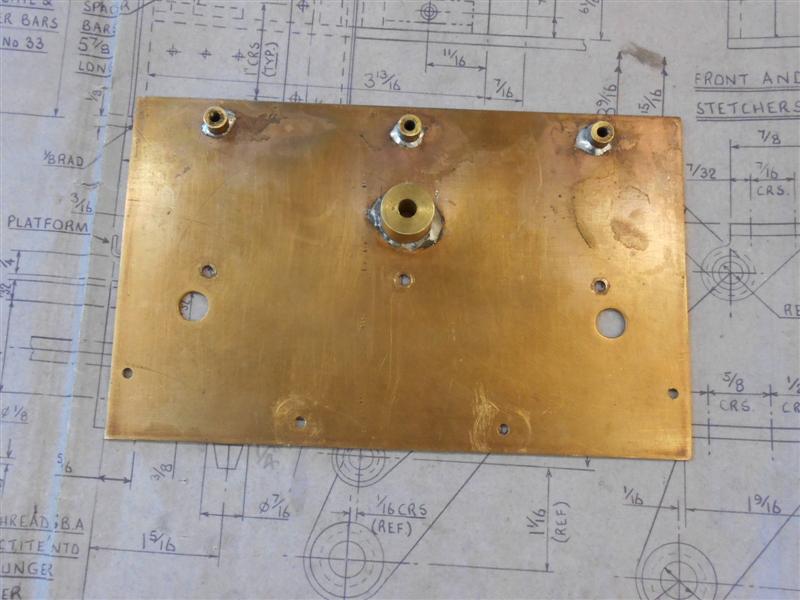 There are two bottom plates made from 16 swg brass sheet joined by a length of 7/32" flat bar. The front one of these carries the lower drawbar pin support which, like it's upper counterpart, is soldered to the plate.  The lower one carries the scoop and brake bellcrank brackets below, and a pair of spacers above for connecting to the top plate. The drawing suggests riveting the two plates together through the flat spacer bar but I have fixed mine with 8BA bolts and nuts. The brake brackets are made from 3mm mild steel plate and are bolted to the plate with the centre screws going into the 1/2" square spacers. I'm not modelling the scoop and associated gear but it can be added later if I change my mind.  The next two views are the lower plates primed and in position.   Thanks for looking in, Steve |
|
|
|
Post by Deleted on Sept 7, 2017 18:43:54 GMT
Looking good Steve...
Pete
|
|
|
|
Post by Jim on Sept 7, 2017 21:36:32 GMT
I agree with Pete you're doing a great job there Steve. That whole front assembly is quite complex but fortunately the tender can be more easily handled when it comes to connecting up the brake linkages etc.
Jim.
|
|
|
|
Post by springcrocus on Sept 9, 2017 18:29:39 GMT
The platform and the deflection plate are both made from 20 swg brass sheet. Both items were cut out with a hacksaw and then filed to size prior to marking out the bending position. For the platform, the material was left a little long to assist with bending and the two notches at the front were cut away. Bending on both items was performed the old-fashioned way of supporting between two hefty lumps of steel and gently peening over with a mallet. 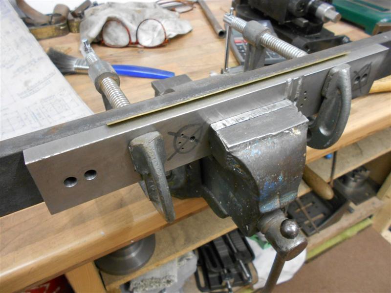 In the case of the deflection plate, the angle was checked with a gauge by eye - not very accurate but good enough to get started. The platform was then set up against angle plates on the mill and the height of the platform lip machined to size. I tried it laid flat and using the end of a milling cutter but it was difficult to support the edge and stop it ringing like a bell. Using the side of an endmill moves the cutting forces down into the material, rather than at ninety degrees, and the lip becomes self-supporting.  The next operaion was drilling all the holes and the plate was clamped on a piece of MDF, trued up and the holes made by using co-ordinate drilling.  The holes at the base of the deflection plate were drilled in a similar manner, the tee slots on the table being deep enough to the allow the material to sit nicely on the 12mm MDF and squared up against the edge of the tee slot. 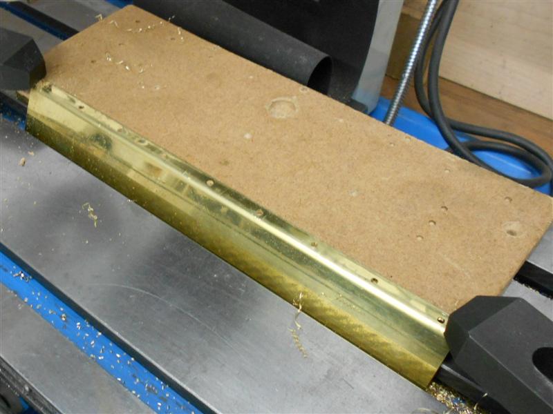 And finally, the two items were test assembled with 3/32" rivets dropped in and set on the framework.  This was the point when I realised that it was nigh-on impossible to assemble all the parts as drawn. Excellent work by the designer/draughtsman.  If I rivet the deflection plate first, I can't fix the rear of the platform to the top plate and nor can it be done the other way. Using nuts and bolts, with the nuts uppermost worked - just - but it was a complete dog's breakfast. I dont see the need to fix the plate at the rear as long as it is resting on the spacer, so I tapped the long spacer bar 4BA and bolted it to the top plate first. Then I riveted the deflection plate to the platform with 3/32 rivets  This can now be bolted at the front and the section along the front of the tank will hold it all together. The three holes in the front of the platform behind the deflection plate are now redundant. After fixing in place, the tank was offered up and the deflection plate trimmed until a snug fit was achieved. I also had to tweak the angle a little but it has gone together satisfactorily.  If, later on, I find that the platform rattles or vibrates, I may cut a pair of slots between the redundant holes and fix a pair of scews on the spacer bar set with a forty thou gap, thus allowing the platform to slide underneath them. Thanks for looking in, Steve |
|
|
|
Post by springcrocus on Sept 14, 2017 21:31:34 GMT
I have made the brake hanger brackets from 1" dia brass bar but because they are inside the frames and completely out of sight, I have changed the design to ensure that the bracket carries the brake hangers, not the shouldered bolt as designed. On the drawing, I have pencilled in an extension to create the pivot point. As with the spring hangers, the holes were drilled first and the work supported on pins to mill the outer form.  I have also done away with the as-cast shaping in favour of simple turning using the 4-jaw independent chuck, followed by counterboring clearances with a slot drill for the nuts to fit on the fixing screws. The spigot is turned to 6mm dia and just over 1/8" long, and the hangers, which are from 1/8" material, have a 6mm reamed hole to match. A simple screw and washer will retain them.  They were then assembled into place and the underframe primed. Also evident in the photo are the guard irons, and the rear tender steps which are a simple brass fabrication. I have made the lower step support as per prototype rather than the single-width bracket which the draughtsman chose to depict.  It's all coming along quite nicely now and the paint makes it look a lot better. Thanks for looking in, Steve |
|
|
|
Post by springcrocus on Sept 16, 2017 18:33:06 GMT
The brake hangers have been made from 5/8" x 1/8" EN3B bright bar and I have changed quite a lot of the dimensions. I started by cutting the material 1/8" longer than drawn because I have increased the hole sizes and made the outer dimensions to suit. All the holes were marked out then drilled and reamed 3/16" diameter, although the upper hole was opened out to 6mm later. A pair of 3/8" dia and one 7/16" dia filing buttons with 3/16" stems were made and these were used to help produce the forms at the ends and also to act as filing guides for the centre hole. A small amount of roughing out was done on the mill but most of the shape was hand-filed.  Rather than make new ones, I modified a spare set of loco brake beams to fit the tender. These are shown as using shoulder bolts which I don't like as I find they are prone to break at the root of the thread so I designed the brake beams to be spigoted, with a 4BA tapped hole at each end for retention similar to the brake hanger brackets instead of a male thread and fitted nut. I had to adjust the lengths to suit what I was planning and this is when it became obvious that the draughtsman had made numerous mistakes which could have resulted in a load of scrap work.  Each beam was held in the independent 4-jaw chuck and the spigot turned to 3/16" dia and a tad over 1/8" long. At the same time, they were drilled and tapped 4BA. When assembled, the hangers will be retained by simply screwing in a short 4BA bolt to full depth.  For the benefit of anyone making a tender to these Les Warnett drawings, the length of the brake beams is incorrect - check on your own chassis. Thanks for looking in, Steve |
|
jools
E-xcellent poster
  
Posts: 200
|
Post by jools on Sept 16, 2017 23:49:20 GMT
Hi Steve
great progress and I am finding it comforting that all these individual components shown here in this, and other similar threads, are beginning to
be recognised as I continue redrafting the Black 5 plans - currently up to sheet 7 of 13 !
It is also evident how similar the component parts are between the two designs and your own personal approach to changes as you see fit or by design errors are really interesting.
I'm still a long way off starting production but am still fascinated by these threads & solutions. Keep up the great work.
Jools
|
|
|
|
Post by springcrocus on Sept 18, 2017 6:43:45 GMT
There is quite a collection of parts that go together to actuate the brakes. I have made a couple of variations to the drawings to suit my tooling; the rods are all threaded M4 and the eyes have been replaced with threaded bosses so that I can adjust for any variation in the brake block sizes. With the forks, I prefer to make the slot first, milling to within twenty thou or so of the bottom, then removing the underneath support and finally plunging the slot drill through at the end of the slot and working outwards till the cutter breaks free. This prevents the cutter grabbing the work and bending it inwards.  Next I drill the cross-holes using packing to stop the part collapsing, and finally to mill away the opposite end if it's double-ended or drill and tap through on the lathe in the 4-jaw chuck if it's a rod end.  Once again, the draughtsman got it wrong. There are two of the adjusting linkages, three components needed for each one or five if one counts the forks. I have used M4 right-hand and M4 left-hand to create the adjuster. The other variation I have made is how I fix the brake shaft levers to the brake shaft. The drawing suggests a 6BA grub screw but I felt this was far too flimsy and have pinned mine with 3/32" taper pins. To set up the drilling, I mounted the shaft in a tiny Vee-block on the milling table.  I only set it by eye, not worth getting the wobbler out for, but a quick check with the old ruler trick seemed OK  They were then set up with a bar through the eyes and resting on parallels to make sure they were level and the holes were then drilled with a 3/32" dia drill as pilot followed by the taper drill. 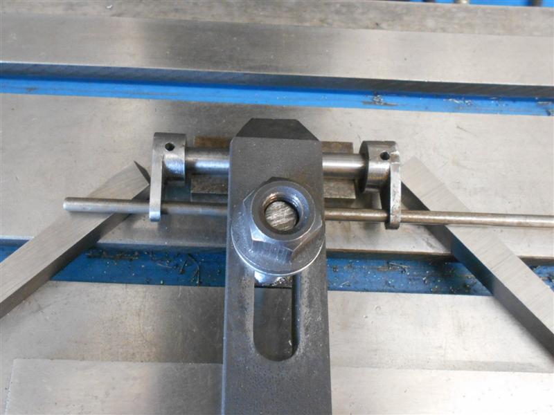 For any who have not used taper-forming drills before, you need to be aware that they have a tendency to grab the material and pull themselves into the hole, resulting in a stalling of the drill for larger sizes (and probable damaged workpiece) and a broken drill for smaller sizes. It is very important that one uses a short, sharp pecking action to keep breaking the cut when using these drills. And they need to be held extremely tight in the chuck. 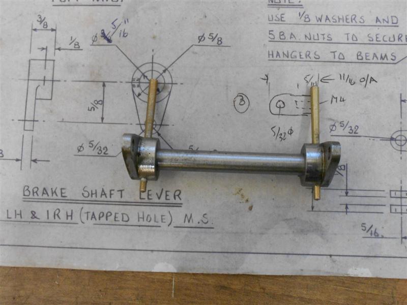 These are nearly all the parts for the brake linkages, there are some more to make but I haven't yet decided how to proceed and will cover this at a later time.  Thanks for looking in, Steve |
|
|
|
Post by Jim on Sept 19, 2017 10:51:24 GMT
I love the pair of turnbuckles you've made Steve very very neat indeed.
Jim
|
|
|
|
Post by springcrocus on Sept 20, 2017 21:37:08 GMT
I covered the tender brake blocks in a separate thread about three years ago but am reposting it here in the diary, rather than linking to it, in the interests of completeness. I have also altered the description a little to better reflect the style of the diary and added some extra information where relevant. When I checked the old thread, I found it was one that had been "PB"ed so I have corrected all the links for any who find it by searching. My apologies to those of you who have a deja-vu moment. It appears that many people favour machining these from scratch using an old car brake disc or similar. There are castings available but the accuracy and finish of these castings leaves much to be desired and the problem of machining them can also present some difficulties, particularly if there is only very basic tools and machinery available to complete the task. Some say that brake blocks were rough-cast in full-scale and you only need to mill the slot, drill the brake pin hole and machine the area that touches the wheel. I, personally, prefer not to have rough castings with minimal machining and would rather finish-machine all over and here's how I went about the task. These are the brake blocks, as supplied, for the BR1 tender (Norman Spinks 5" gauge Britannia drawings with Les Warnett's BR1G tender).  First, I cut the blocks into individual pieces and marked out where I wanted the brake pin hole to be in each blocK. The hole size in my blocks is specified as 3/16" so I drilled and tapped these holes at 2BA, this being the largest thread that is SMALLER than the finished hole (you'll see why in a minute). The next job was to face front and back of the blocks for a flat and level finish. Facing off in the lathe seemed the easiest way so a means of holding them was needed. Because I have soft jaws for my chuck, I made a carrier plate onto which I could bolt the brake blocks and then load to the soft jaws. 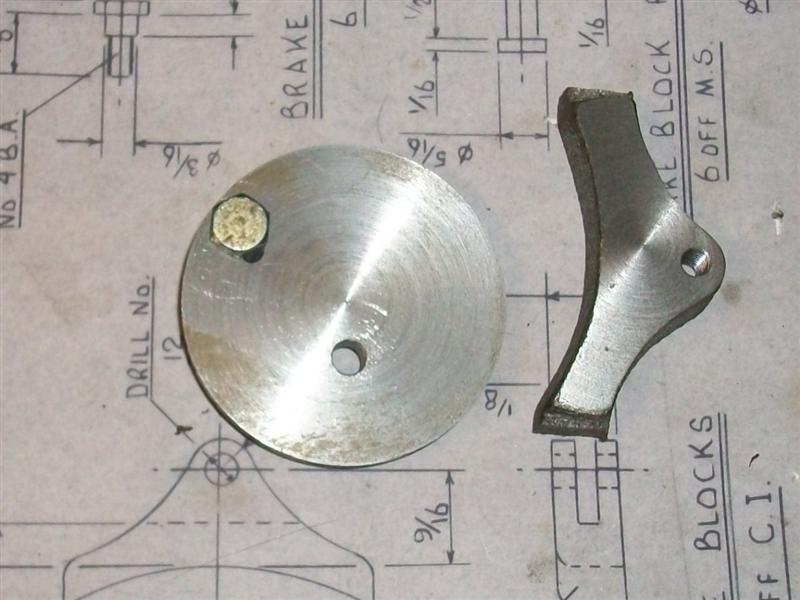 I happened to have a mild steel blank of 1.7/8" dia x 1/4" thick but any old bit of steel would do. After facing off and turning a dia for trueness, then reversing and facing the back, I have drilled a 2BA clearance hole in it to mount the brake block, bolted from the back, and also added an anti-rotation pin to hold it firm against the cut.  Once both sides were faced, the next thing was to get the length of the block machined which I did in my small milling machine. Each brake block was placed in the vice using the bottom slot of the vice to centre it and then aligning the block by eye. There will bound to be a more accurate way but I don't think it matters that much.  Because the width of my vice (1.618") is less than finish size of the brake blocks (1.750"), I was able to mill one side to size (0.066" from side of vice) and then do the other side to finish at the required size.  Next I had to clean up the outer edges of the brake blocks so it was time to open the tapped holes up to their finished size. One of mine was a bit adrift so I opted to mount the blocks in the vice, holding on the milled flats, and use a 3/16" slot drill to align the holes more accurately. Some of the blocks have a slight witness of the thread but it's not important - there's a pin through there on assembly.  I had forgotten to take a photo at that point ,so that last picture was taken at the end. Most castings have a draft angle and I bolted mine together in pairs with the smaller faces together and then started to clean up the profiles using a carbide burr in my hobby drill...  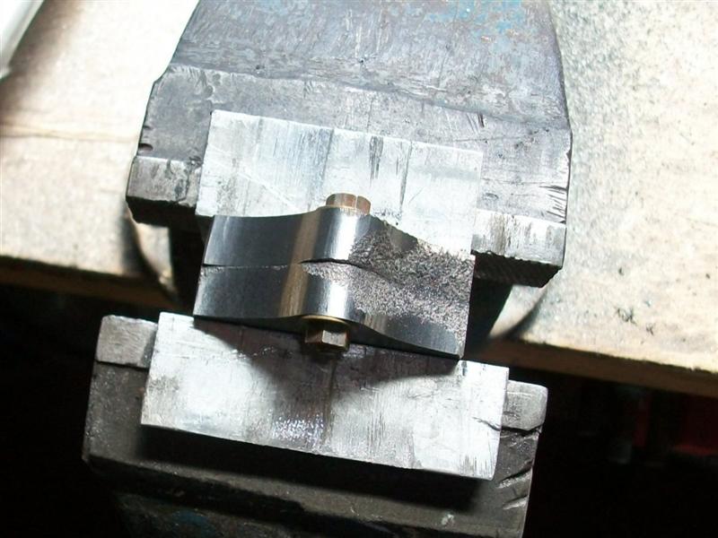 ...and finishing off with a small drum sander for the internal radii and my belt linisher for the external radii.   That only left the wheel-form part of the job to do and the slot. Using the same soft jaws as earlier, I drilled and tapped a 2BA thread in the top of each jaw...  ...and loosely bolted three of the blocks to the jaws. Then I gently clamped the jaws onto a finished wheel to align them and finally pulled the bolts up tight. I used cap screws because they are normally high-tensile and you can get them good and tight.  Then I wound the jaws down onto an adjustable ring (normal soft-jaw accessory) to leave about thirty thou to come out. I also set the compound slide over to about two degrees to enable putting a slight taper on the blocks.  I would have liked to have included some sort of anti-rotation pin to the setup but decided that all would be okay with small cuts and a gentle touch.  ] I took five thou depth of cut from the cross-slide and used the wheel as a gauge. I managed to go a bit too far on the first set so I undid the chuck, adjusted the setting ring to a bit smaller, and had another go. Once to size, I used the compound slide to take a final cut to match the wheel profile. The brake blocks are symmetrical so no special attention has to be paid to orientation, unlike the loco blocks. Finally, it was time to put the slot in. I don't have much in the way of slitting saws so opted to mill them out using a 1/8" slot drill (of which I have plenty).  However, they are not deep enough so I freehand ground a bit of the shank down and milled the slots in two hits, saving my home-made long-series slot drill to finish the depth. And here is the finished article - well six actually.  Thanks for looking in, Steve |
|
|
|
Post by springcrocus on Sept 24, 2017 16:21:15 GMT
The tender wheels have been machined from castings and appeared to be of reasonable quality. I have machined all of the wheels for Britannia in a similar fashion, although I only used a turning fixture for the tender wheels. After a small amount of fettling to clean up the spokes a little, each wheel was mounted in the independant four-jaw chuck, front face inwards and holding on the tread, and adjusted until the boss ran reasonably concentric. The back was then faced off till clear of witnesses and a further ten thou taken. The bore was drilled 1/8" undersize, followed by boring with a small boring bar to 1/64" undersize and finally reamed to the correct size. The O/D of the wheel flange was also skimmed to clean up but not to size. The wheels were then mounted in soft jaws on the three-jaw chuck and the bosses faced to clean up followed by machining the face of the wheels. The object here was to try and get the correct look of the wheel-rim against the spokes without removing too much metal and leaving the wheel thickness undersize. Once I was happy with this, I then continued facing off the boss to the correct distance from the rim. The tyre was then turned to about sixty thou above finished size to get it concentric for holding on the next operation. I'm missing a couple of pictures here, and I've checked all my backups, but a wheel in a chuck doesn't look like much else so no great loss. The wheels were then reversed in the chuck and the backs machined down to finished thickness. The O/D of the wheel-rim was also skimmed to finished size and a radus filed onto the rear edge.  For the tender wheels only, I made a fixture which allowed me to mount each wheel on a mandrel correctly sized to the axle holes, held with a nut and washer, and with a driving pin to provide positive drive through the spokes. 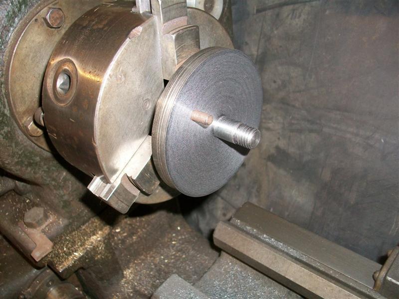 A piece of tool steel was ground to produce the root radius of the tyre and flange and the compound slide set over to two degrees. Using this tool, itself set over to the correct five degree angle, the flange was faced off to the correct thickness and the saddle was locked at this position. The compound slide was then retracted and the tyre machined to the correct angle using the compound slide instead of the carriage. Care was taken near the end of each cut to get a nice blend with the root of the flange.  Once finished, I filed the radius to the edge of the flange and the wheels were complete except for further fettling of the spokes. Thanks for looking in, Steve |
|