|
|
Post by springcrocus on Mar 28, 2015 19:38:02 GMT
The rear beam comprises the large full-width plate from 18 swg mild steel and the main beam from 10 swg mild steel. The main beam has two rubbing plates for the tender buffers riveted to it, and the central stand-off bracket which the drawbar passes through is bolted to it with 6BA bolts. Both plates were first marked out and cut to shape by hand, except for the platform support cutouts which will be done later, and were then co-ordinate drilled using the DRO on the vertical mill.  I could have marked out and free-drilled the holes with confidence but it was easier on the mill. The drawing suggests marking off eight of the holes from the pressure brackets but I have chosen to do it the other way round, spotting through the beam to the pressure bracket.  The central stand-off bracket is a fairly rough gunmetal casting and a little thought went into the machining sequence. I decided to first mill the top and bottom edges edges square to the sides but left twenty thou up on finished size...   ...and then face the back to the nominal size. To get it level, I set four screws into the rear beam and adjusted them to the same height. This then went into the bottom of the milling vice and the casting settled on top. 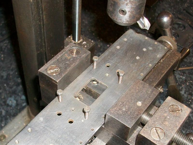  There is no size given on the drawing but scaling from the drawing, which is normally inadvisable, worked out at about 125 thou. It wont matter as long as I remember to make the drawbar to suit, not just to drawing. I could have made this bit in the 4-jaw chuck it's a bit quicker in the mill. Then it was back onto the angle plate to finish the edges all round, a load of filing and sanding, followed by marking out and drilling the 6BA clearance holes.  It is essential that the holes for fixing to the pressure brackets are drilled and tapped before riveting the rubbing plates on since they get covered by these plates and tapping would be nigh on impossible after. The photo shows the rubbing plates riveted on and the central stand-off bracket about to be bolted on. Finally the two plates are fixed together with nineteen 10BA nuts and bolts. Not long now before I start to bolt all these bits together. Thanks for looking in. Steve |
|
Midland
Elder Statesman
  
Posts: 1,875
|
Post by Midland on Mar 28, 2015 21:07:09 GMT
I think I wil hire you as my setup consultant, thank god you are just a skip and a jump away!!! Beautiful work!m very jealous!!
D
|
|
|
|
Post by springcrocus on Mar 29, 2015 15:01:57 GMT
Just a quick update, bolting a few bits together...   That's it for a few days, got a busy week ahead of me. Thanks for looking in. Steve |
|
|
|
Post by Geoff (Carlisle) on Mar 29, 2015 20:36:41 GMT
Hi Steve isn't it a great feeling when the bits and pieces all come together, and to note not to make the engine to tender drawbar to the drawings as they are too short.
Geoff (Carlisle).
|
|
|
|
Post by springcrocus on Apr 4, 2015 18:09:40 GMT
The front buffer beam assembly consists of the main beam, the drawhook strengthening plate, four pieces of steel angle for connecting to the main frames and three pieces of 5/16" brass angle for affixing the footboards. The front beam consists of numerous rivets which are decorative only. Unfortunately, I do not have a photo of the main beam before riveting but I will describe how I made the various bits and fitted them together. The first job was to drill all the holes in the front beam using the milling machine with the DRO. The mild steel blank, with a piece of 10mm MDF underneath, was clamped squarely to the table and clocked up to set a datum. The clamps were positioned on the sacrificial areas at each end so that all the drilling could be done as a single operation. I could have marked the plate out and free-hand drilled the holes but co-ordinate drilling is more accurate and a wobbly line of rivets looks terrible. After sawing the four pieces of angle they were first milled to shape and then flycut to make them truly square. The frame mounting holes were then drilled 2BA clearance and the angles bolted to the frames, making sure they were square to the frame ends. One of my frame spacers was also clamped between the frames as close to the angle as I could get it to correctly set the width.  The front beam was then offered up and clamped to the outer angles and the inner angles drilled through the beam, a rivet being inserted after each hole was made. The clamps were then moved over to the inner angles and the outer angles drilled and pinned as before. I am cheating a little here because the front beam was already assembled so I ground out some of the rivets and pulled it apart so that I could set up these two pictures for the benefit of those who may not be quite sure what I was referring to.  Once all the holes were drilled, the beam was disassembled and everything marked with felt tip to ensure the angle pieces didn't get mixed up. The cutaways at the ends of the beam were sawn and filed to shape and any tapped holes were threaded at this stage. The drawhook strengthening plate was also made and this was the first thing to be riveted on, followed by filing the rectangular hole to somewhere near size. Once the drawhook is made, there will be another filing session to marry both parts together. All of the dummy rivets were fixed next followed by the rivets to the angle pieces, making sure the angles went back to their correct places. Once this was finished, the buffer beam assembly proved to be a snug fit to the frames so the packing piece was removed and the assembly bolted on properly. 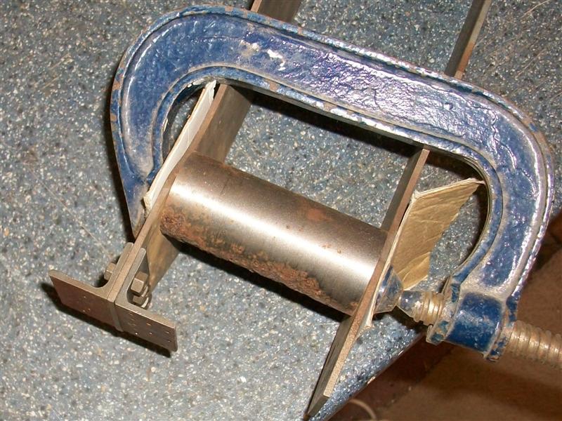 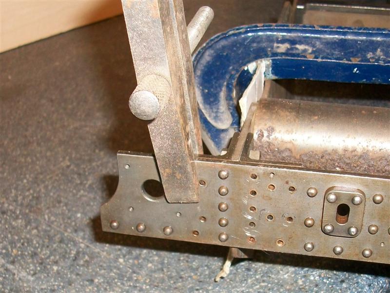 Now that the basic frame is assembled I shall start to make all the other parts on the first two drawings such as horns, steam brake valve etc. Thanks for looking in Steve |
|
|
|
Post by springcrocus on Apr 6, 2015 16:34:54 GMT
Just another couple of pictures - I'm sure you're all getting fed up of pictures.  First, this is a close-up of the front end once bolted together...  and this one is a composite of the overall main frames. Those of us building Britannias know how big the loco is, for those of you thinking of building your own make sure your bench is big enough.  That's a one metre rule stood alongside, and don't forget to add another 600mm for the tender.  Steve |
|
|
|
Post by Jim on Apr 6, 2015 21:10:07 GMT
They are not only big they are also very heavy. Mine lives on one of those hydraulic lifting tables.
Jim
|
|
|
|
Post by springcrocus on Apr 11, 2015 16:55:59 GMT
The main horns were supplied as gunmetal castings and need machining all over, although there was not a lot of metal spare so a little thought was needed to ensure a good cleanup. The important bit is obviously the fit to the frames so I decided to try holding on the inside edges. How I solved it was to use my self-centering 4-jaw chuck on the mill which I first set up square to the table. 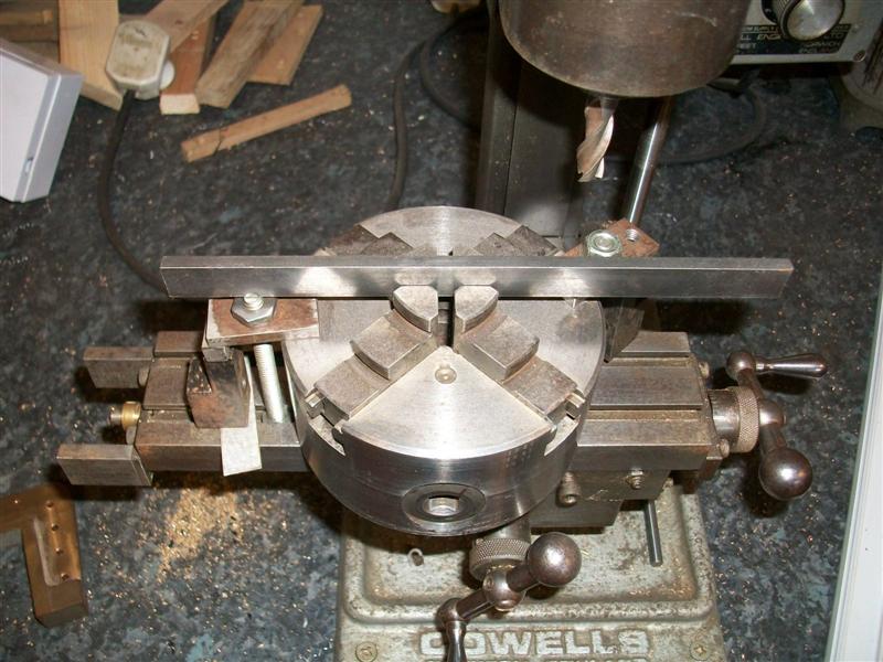 By expanding the jaws, I was able to get a good grip on the horns which allowed me to mill the tops and outer edges of the flanges and the seating faces. These in the picture have been finished but this is how I held them.  Once I had a flat face and square edges, it was easy to set up in a normal milling vice to machine the opposite side and drill the holes. The trapezoidal edges were formed by using a sine bar and bolted to an angle plate.  The inner faces of the horns have yet to be machined. There is only about twenty thou per side to come off and these will be milled to size whilst bolted to the frames to ensure the axles are all parallel to each other. It was at this point that the extra shaping was done on the frames to ensure a snug fit for the horns. Here they are just held on with a couple of bolts in each.  Thanks for looking in Steve |
|
|
|
Post by Deleted on Apr 11, 2015 20:51:19 GMT
nice work Steve... I was surprised when first discovering that the Britannia's had their horns on the outside whereas for most loco's they are on the inside. can't remember now who's build it was when this was talked about, I kind of like it as it adds more interest to the frames, seems a shame to hide the horns on the inside....  Pete |
|
|
|
Post by springcrocus on Apr 13, 2015 16:51:51 GMT
The horn stays are made from gunmetal castings and just need the horn mating faces and the frame stay lugs to be machined but I chose to clean up the underside as well because it makes marking out and drilling easier. Since the castings were reasonably flat, I was able to just give the bottoms a quick dab on the linisher and then mount them on the mill as shown.  I clamped them onto a bit of packing but because there is only room for one clamp, I set a gate at each end to stop the pressure of the cut moving them. With this setup I was able to mill the back, sides, tops and lug tops at one visit. It still needed a gentle touch, though.  This just left the bottom to be machined which I was able to do in the milling vice, and the 2BA clearance holes for bolting to the horns which were marked out and drilled. I also dismantled the horns from the frames and marked out, drilled and tapped the 2BA holes in these.  I have not drilled the frame stay holes in the lugs yet, if I get the hole positions wrong it would distort the frames. These will be spotted through from the frame stays which I will make next. The 1/4" hole for the spring gubbins can be sorted later, too.  Thanks for looking in. Steve |
|
|
|
Post by springcrocus on Apr 19, 2015 12:08:21 GMT
The frame stretchers are the final part in holding the frames at the correct width and fit onto the horn stay lugs. The drawing calls for six of these but actually only five are needed because the the leading stretcher on the rear horns cannot be fitted, the bracket for the steam brake cylinder gets in the way.  I have made them from 3/8" square mild steel, parting them off to length on the lathe using the self-centering four-jaw chuck. However, they could just as easily be sawn oversize and then faced or milled to length. There is nothing that needs to be particularly accurate here other than the holes. Next, I marked out the cross holes in each end and drilled them 3/32" before milling the two slots using an endmill with the work held in my four-jaw chuck. I am going to be spotting through these to the lugs on the horn stays and I prefer to use a small but reasonably rigid drill for this. I find it transfers more accurately and it's easy to open the holes to size afterwards.  Once the slots were in, they were offered up to the horn stays and spotted through. I also used my frame spacers to ensure the frames were at the correct distance apart. At this point all the horn stays and stretchers were numbered so that they could be dismantled, drilled to size and later reassembled without them all getting mixed up. It's probably unnecessary in this instance but I think it's a good habit to get into and may save some grief at a later date.  The last job was to turn the relief diameter in the centre section. This was done by holding in the four-jaw chuck and supporting the opposite end in a simple cup bored to be a snug fit to the square bar with a centre in the back. Just sliding the parting tool back and forth along the bar worked a treat despite the intermittent cut although I did take quite a few passes. A bit of emery cloth to polish finishes the job.  The last photo shows one section assembled. 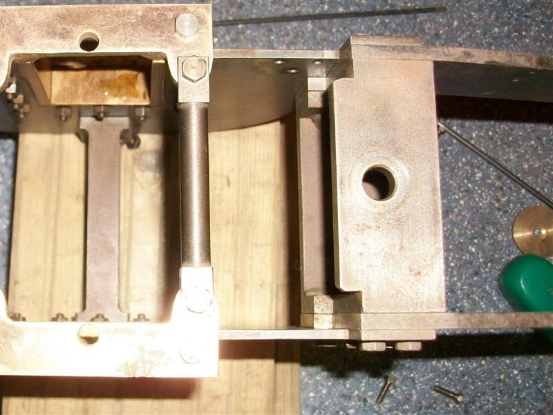 Thanks for looking in. Steve |
|
|
|
Post by Geoff (Carlisle) on Apr 22, 2015 20:08:05 GMT
Hi Steve, not getting fed up with the pictures.
Geoff (Carlisle).
|
|
stan
Seasoned Member

Posts: 110 
|
Post by stan on Apr 22, 2015 21:13:21 GMT
Hi Steve
We never get fed-up looking at brilliant work gives us something to aim at and it is always nice to see how other model engineers do things.
Stan
|
|
|
|
Post by springcrocus on Apr 26, 2015 21:29:05 GMT
The pump body is one of the parts that I cannot re-create my original setup but I have described how I made it for completeness. Although the drawing calls for the pump body to be made from a gunmetal casting, I decided to machine mine from 2" diameter brass since I had some in stock. The first alteration I made here was the smaller diameter of the pump body. The drawing calls for a 1" x 32 tpi thread on the end with a 15/16" relieved dia along to the 1" diameter locating spigot. To me, this is a nonsense and I decided to make the diameter 24mm with a M24 x 1mm pitch thread on the end. I will also change the plunger to 16mm and use a 4mm section O-ring. After facing my billet to length, I held on the last half inch using soft jaws in my 3-jaw chuck and did all the maching in one visit, starting with centre-drilling, drilling and boring the 5/8" diameter hole, drilling the small hole at the bottom, turning the two outside diameters, reaming the bore and finishing with screwcutting the thread. For this, I used a standard screwcutting tool with a 1mm pitch insert. The advantage of using an insert is that as soon as you see the outside diameter getting a light skim, assuming you have turned the O/D to nominal size, then you are close enough to size to stop cutting and you have a full-form thread. When I originally made this part, I had the luxury of an Ainjest high-speed screwcutting attachment on a Colchester Triumph 2000 so there is no discernable run-out point but if making it on my simple centre lathe today, I would just create a decent length of undercut and run into that. The length of thread is unimportant as long as it is long enough to allow the nut to screw on fully.  To form the back section, I held the part in a 3-jaw chuck on the mill and machined the four faces to size.  The suction and delivery connections were made by holding the work in my normal milling vice and drilling and tapping the first hole 3/8" x 32 tpi and then turning the job over and doing the same again from the other side, bearing in mind that the two holes are different depths. I also drilled the through-hole at this point, being careful because I was breaking into the cross hole that was drilled to depth while on the lathe.  Final job was to mark out and drill and tap the six mounting holes which are on a PCD of 1.1/4". The drawing shows a distance of 7/16" between holes but this is incorrect, the distance should be 0.442". When I made the pump stretcher, I used the proper co-ordinates and have to do the same again here if I want everything to fit! Thanks for looking in. Steve |
|
|
|
Post by runner42 on Apr 26, 2015 23:00:29 GMT
Hi Steve,
didn't want to interrupt your flow, but there is something (amongst many other things) that I struggle with and that is how to mark the holes at the required PCD on a complex shape? Establishing the PCD is a challenge and I assume you didn't use a centre punch and hammer for drill positioning?
Brian |
|
|
|
Post by springcrocus on Apr 27, 2015 8:04:19 GMT
Hi Steve,
didn't want to interrupt your flow, but there is something (amongst many other things) that I struggle with and that is how to mark the holes at the required PCD on a complex shape? Establishing the PCD is a challenge and I assume you didn't use a centre punch and hammer for drill positioning?
Brian Hi, Brian I've done a thread here describing how I did this. Steve Sod it! How does one create a link to another thread?  Sorted it! Had a double lot of http: in the link. Found the problem by looking at the BBCode page.  |
|
|
|
Post by ejparrott on Apr 27, 2015 8:19:42 GMT
|
|
|
|
Post by Deleted on Apr 27, 2015 8:20:44 GMT
|
|
|
|
Post by peterdanastas on Apr 27, 2015 11:01:44 GMT
As for holes which should not be there I found a product called KNEADIT. It looks a little like plasticine .All you have to do is cut a bit off roll and roll it in your fingers fill the hole up and smooth up In AUSTRALIA it is available at local hardware shops and it is cheap
|
|
Midland
Elder Statesman
  
Posts: 1,875
|
Post by Midland on Apr 27, 2015 12:47:26 GMT
Steve What impeccible timing, I am trying to make a pair of new safety valves a la Gordon Smith and his 'soft pop type' as my current ones just empty the boiler all the time. I have printed your post and am now out to try to do it on the little screw bit on the top. Peports later!!! Bless you for that. And thanks to Ed for the link!! David Read more: modeleng.proboards.com/thread/10616/marking-out-pitch-circle-diameter#ixzz3YVt4euFS |
|


