|
|
Post by Doug on Jun 8, 2015 20:11:10 GMT
Ok so the way I have been taught to have it my a range of people is to have a thou or 2 at most float of the bobbin on the valve rod, this allows the bobbin to essentially float within the bore and not affected by the movement of the valve rod its self as the motion work will cause the rod to not always run true and concentric within the bore. I haven't seen any LBSC drawings to see how he has drawn it but the way I have the 9f and the way the '5' is when I got it apart yesterday is there is a rear locking nut to set the position of the bobbin on the rod and the front PAIR or locking nuts lock against each other allowing this 1 or 2 thou play along to the rod. Baring in mine most holes through bobbins are not a clearance hole on the valve rod but significantly larger if you were to lock the bobbin up on the rod and it were not dead center you would get some pretty bad and uneven wear in that bore. This is just what I have been taught as typical practice and what I have found in grandads locos too so I trust that advice, if you consider a slide valve loco, the valves themselves are only a snug fit on the buckle being guided along the surface rather than fixed to the valve rod. Adam This is too how I "read" the design concept. I cannot envision any up and down movement with the design I have even if it was worn badly besides 11 mm of gunmetal bearing surface will take out any issues and make it run true. |
|
|
|
Post by joanlluch on Jun 8, 2015 20:56:28 GMT
Thanks for that Adam, I'm really surprised. I guess it's done that way because the fit in the sleeve is so close that the slightest misalignment would cause it to bind up. Roger, what Adam just described was implicit in Michael's posts and mine in your thread some hours ago. I thought this was already known by you, so maybe you should reread now said old posts to see the full picture. |
|
|
|
Post by Deleted on Jun 8, 2015 20:57:04 GMT
I think I'll go and bang my head against the wall for an hour or two .
|
|
jma1009
Elder Statesman

Posts: 5,901
|
Post by jma1009 on Jun 8, 2015 21:33:37 GMT
hi doug,
i am very much enjoying your 'build' thread and as you know have taken a keen interest in problems with Butch and your Speedy build.
if you are using now solid rings i would firstly change them from brass to bronze that is dissimilar to the liner bronze, and make them as per LBSC and fit them as per Don Young. have a solid one piece bobbin of bronze and no chamfers on them to restrict port opening. by all means use what you have made to get the liners dead smooth, then change over to new solid bronze bobbins.
as michael and joan have stated there is an element of up and down movement on the valve forked end. in LBSC's 2.5"g locos doing very little work this wear is insignificant. but on a 5"g Speedy hauling a decent load this wear will quickly cause play without roger's valve crosshead or front cover support. what is ok for slide valves isnt ok for piston valves, though personally ive always fitted front cover tail guides.
cheers,
julian
|
|
|
|
Post by Cro on Jun 8, 2015 21:58:21 GMT
I think I'll go and bang my head against the wall for an hour or two . Before the head banging starts, I have to say although I didn't read yours and Joan's posts in full i think the way I may have put it was in its simplest, model engineering terms. I may be wrong as like I say I didn't fully read them. Sometimes saying or reading it from a different source can make things much clearer. Adam |
|
|
|
Post by Doug on Jun 9, 2015 5:39:07 GMT
hi doug, i am very much enjoying your 'build' thread and as you know have taken a keen interest in problems with Butch and your Speedy build. if you are using now solid rings i would firstly change them from brass to bronze that is dissimilar to the liner bronze, and make them as per LBSC and fit them as per Don Young. have a solid one piece bobbin of bronze and no chamfers on them to restrict port opening. by all means use what you have made to get the liners dead smooth, then change over to new solid bronze bobbins. as michael and joan have stated there is an element of up and down movement on the valve forked end. in LBSC's 2.5"g locos doing very little work this wear is insignificant. but on a 5"g Speedy hauling a decent load this wear will quickly cause play without roger's valve crosshead or front cover support. what is ok for slide valves isnt ok for piston valves, though personally ive always fitted front cover tail guides. cheers, julian Hi Julian Gunmetal or definitely bronze? Thing is I know my two valve liners are slightly different material (different shades of pink when machined) so not too sure what type to use? Gun metal is easy as its a halfway house and the liners are definitely bronze. thanks, doug |
|
|
|
Post by Roger on Jun 9, 2015 5:56:42 GMT
I think I'll go and bang my head against the wall for an hour or two . Before the head banging starts, I have to say although I didn't read yours and Joan's posts in full i think the way I may have put it was in its simplest, model engineering terms. I may be wrong as like I say I didn't fully read them. Sometimes saying or reading it from a different source can make things much clearer. Adam Indeed, some things get so bound up in long detailed descriptions that a simple point is lost. |
|
pault
Elder Statesman
Posts: 1,496
|
Post by pault on Jun 9, 2015 5:58:55 GMT
Hi,
Yep the way I have always fitted piston valves is for them to be floating on the piston rod with as little clearance as possible between the nuts and bobbin. one thing that does help with sealing on plain bobbins is to put some oil grooves on the heads. 3 or 4 groves put in with a relatively sharp pointed screw cutting tool about 5 thou deep make a significant difference to the sealing especially as the bobbins wear.
As for wear of the bore I have never found any really significant wear on valve liners even on a 1940's build loco. when you look at the distance the valve moves (especially if you notch up)and the speed it does it at it is actually fairly slow moving
Regards
Paul
|
|
|
|
Post by Deleted on Jun 9, 2015 7:16:36 GMT
Before the head banging starts, I have to say although I didn't read yours and Joan's posts in full i think the way I may have put it was in its simplest, model engineering terms. I may be wrong as like I say I didn't fully read them. Sometimes saying or reading it from a different source can make things much clearer. Adam Indeed, some things get so bound up in long detailed descriptions that a simple point is lost. I'm gone . |
|
|
|
Post by joanlluch on Jun 9, 2015 8:50:54 GMT
Indeed, some things get so bound up in long detailed descriptions that a simple point is lost. I'm gone . Hi Michael, I am sure Roger didn't imply to direct his comment to someone in particular or to imply that long descriptions were not useful, quite the contrary. To me that was a general comment. In fact, with his post I think he just acknowledged (possibly regretted) that he actually had missed something. This kind of things happen all the time in regular conversations, one exposes a subject assuming a known background or basis which is just omitted from the exposition. But the other person may not have heart of that and thus he may loose fundamental ideas. That's not either the fault of the person who exposed the subject or the person who listened, it's just a background disconnection between the two. So, in my opinion your descriptions are still very appropriate and particularly useful for most of us. |
|
|
|
Post by Doug on Jun 13, 2015 10:28:15 GMT
Ok I have been making the bolts and pins for the motion this morning all the bolts are made to a shoulder so I can tighten them securely without squashing any joints together  The finished article 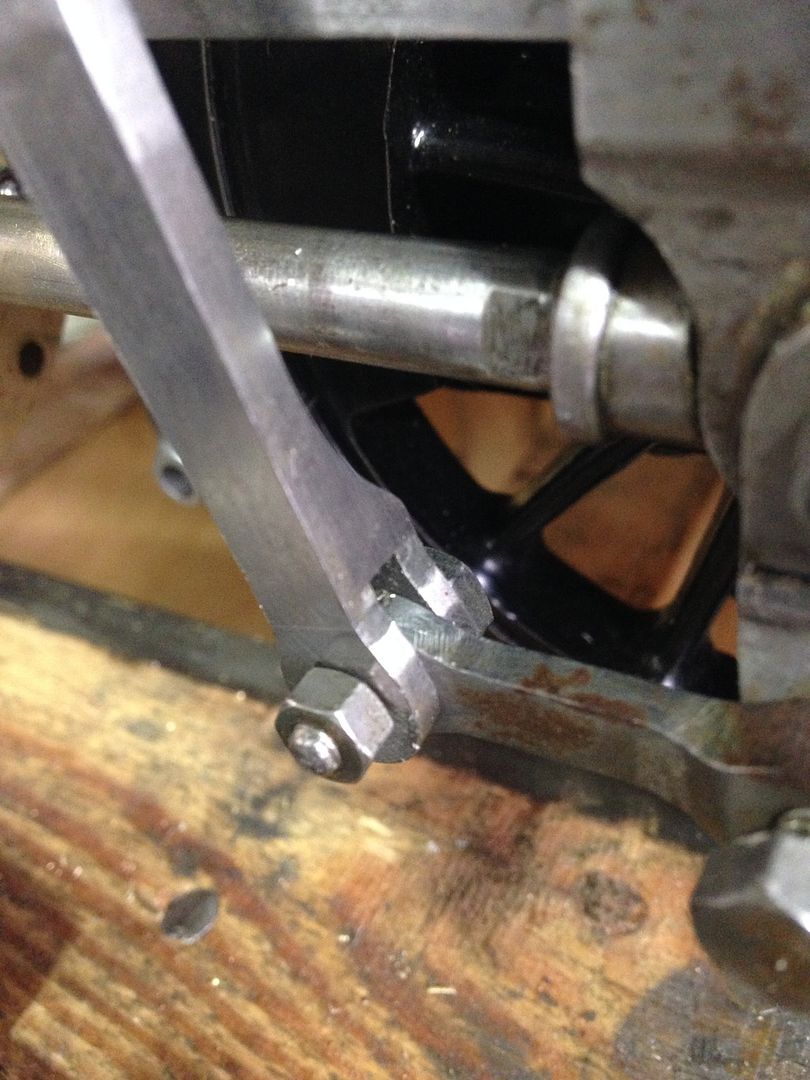 I have found a clearance issue at the valve rod attachment point I haven figured out how I am going to fix this I think I will trim it down to give the bolt clearance I need 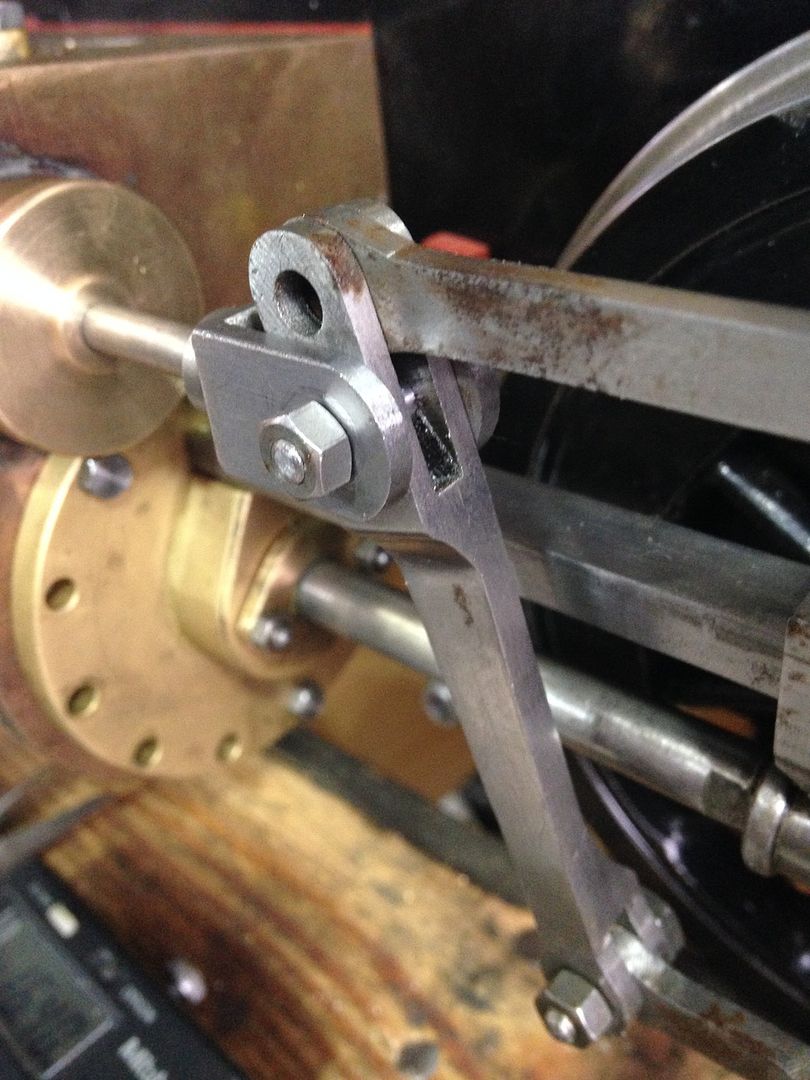 Got a couple more of these to make (plus a couple of bolt heads to make on the cnc) two sets of bushes for the radius rod then the return crank and then it's the air test  |
|
|
|
Post by Roger on Jun 14, 2015 17:21:05 GMT
Good progress Doug. One thought about the pin is to just make it the same width as the combination lever and have a small roll pin through the radius rod into it to stop it sliding out. Obviously you could just make a cutout in the rod end to miss any bolt but that might not appeal to you. I have a similar situation but I'm going to rely on the crosshead to stop the pin from falling out.
|
|
|
|
Post by Doug on Jun 14, 2015 17:57:49 GMT
Sounds like a plan but I may put the roll pin in the fork instead as the radius rod has a bronze bush  I have had a quick look how others have cured the same quandary and it ain't pretty! So the roll pin looks fave |
|
|
|
Post by Roger on Jun 14, 2015 18:51:40 GMT
Just one more thought.... you could make a shouldered pin that has a very small shoulder indeed so it clears the front. Then you could make a substantial cutout on the rear where it's hidden and have a thick washer that has a roll pin.
|
|
|
|
Post by Doug on Jun 20, 2015 20:06:10 GMT
Well it's taking an awful lot more time to do all these fiddly bits a lot more than I could ever have guessed. Right my next little job is the radius arm bearings I have chosen bronze for these as they are going to be taking quite a bit of hammer. 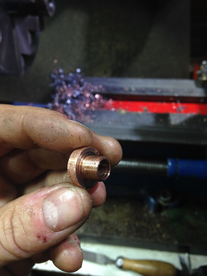 It's a 3/8x 40 thread although I will be fixing them with six bolts so not really required I made a mandrel to hold the little blighters while I turn and drill them 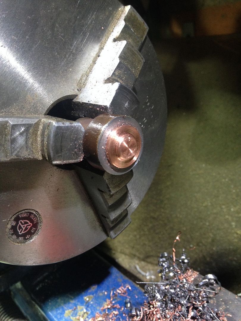 In situe although they need to go on the mill next to get the holes in 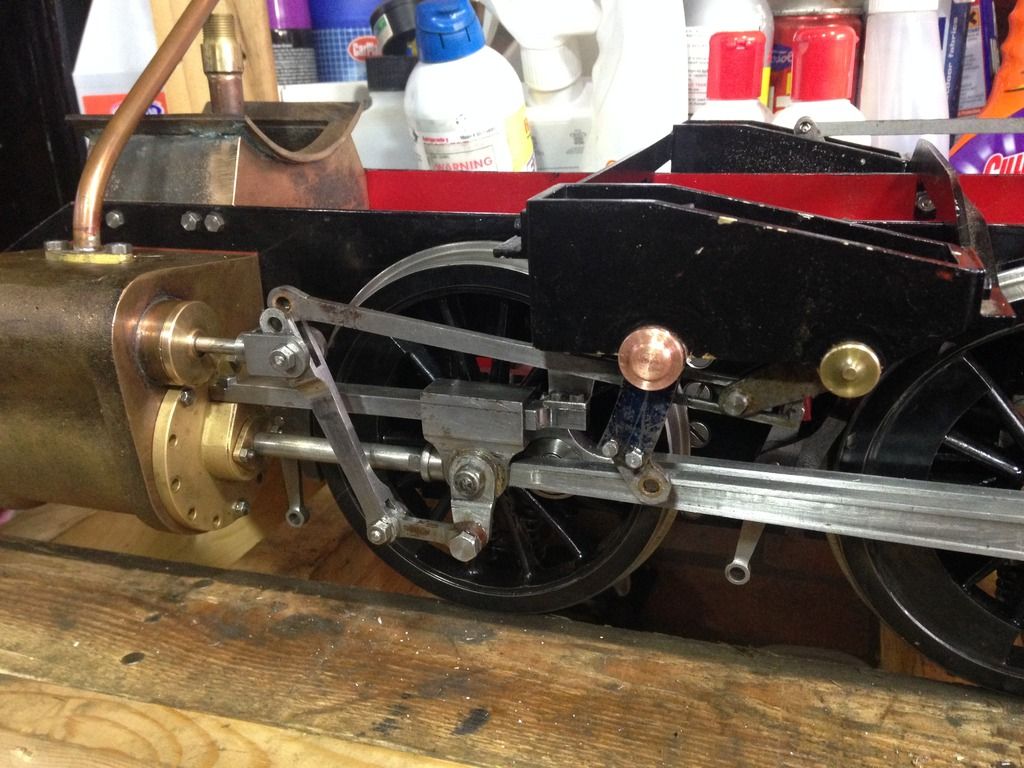 I should only have another four or five bolts to make and I should be set for testing |
|
|
|
Post by Doug on Jun 21, 2015 16:56:21 GMT
Ok a little more done, I got the back bush milled up with a 3/8" hex so I can tighten it up and the holes for the bolts on the front    I need to make an 11 ba spanner to fit these bolts |
|
|
|
Post by Doug on Jul 5, 2015 21:02:21 GMT
Not a massive amount of progress but I have resolved a couple of issues, I have made the gear frame links stiffer and made an 11Ba spanner for the little bolt heads and a small tap wrench for the 10ba tap  |
|
|
|
Post by Doug on Jul 11, 2015 8:42:57 GMT
It's still slow going but I guess this part always is lots of little jobs to tidy up anyway I used Rogers idea of tiny shoulders for my top bolt.  I turned the nut down too to give clearance and I moved the full range with no issues. The best bit is it looks normal from the side which is all most people will see once the tanks are on  |
|
|
|
Post by Doug on Jul 12, 2015 14:58:49 GMT
Made another step forward today while making the last of the motion bolts I found the combination lever was hitting the cylinder cover when it was at TDC so I turned the combination lever around and made a spacer for the drop link bar it all fits quite nicely and the bolts are all 4BA now so it looks a little better too  Is it normal at this stage for it all to get a bit tight it feels like it would benefit from a run in session on my rolling road? 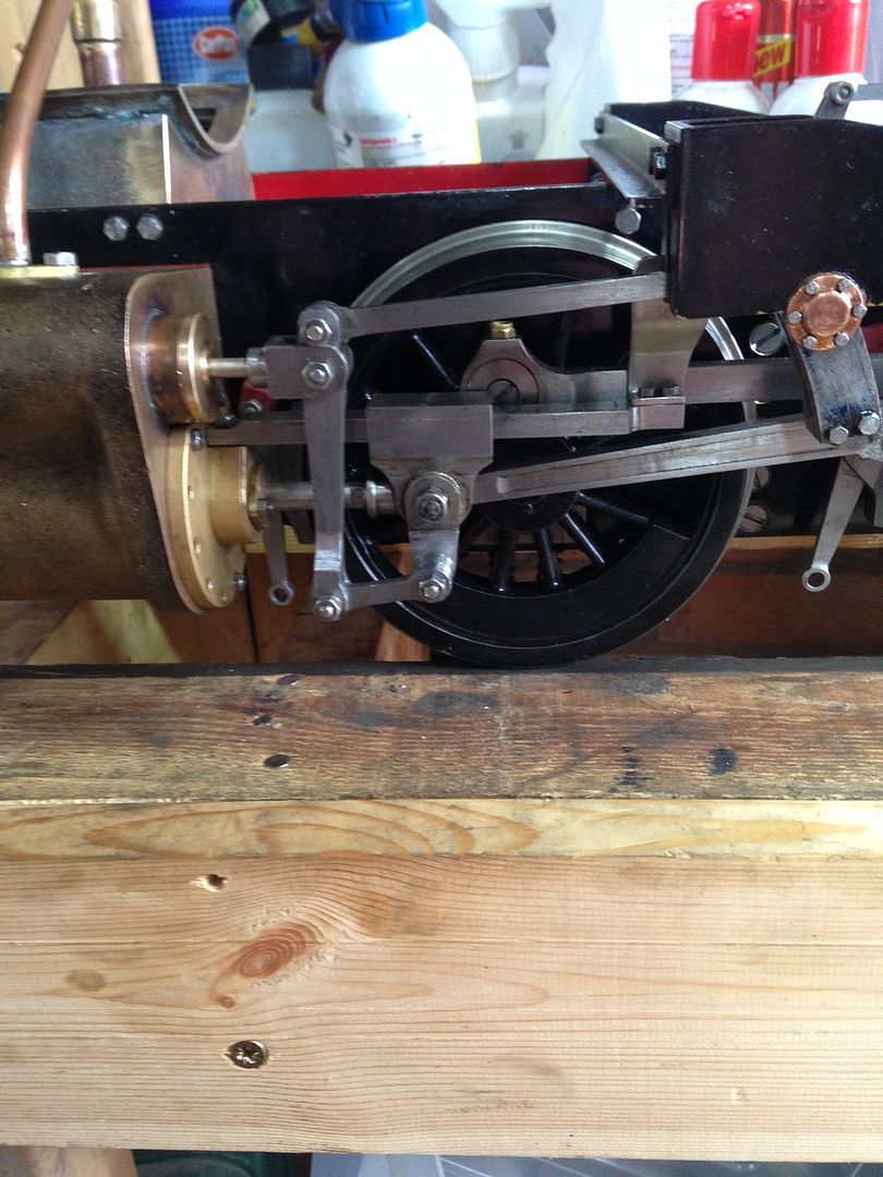 |
|
|
|
Post by Doug on Aug 9, 2015 15:22:13 GMT
I made a start on the return cranks today it turned into a bit of a disappointment as the program I had wasn't very good and I snapped a tool.  So while I was having my first go at making the cranks I decided to make the safety valves for the cylinders as its all lathe work till I make the holes in them. I also finished off the cylinder gaskets and screwed up the covers hopefully for the last time So here is a pic of the safety valve it needs the holes milling into it later. 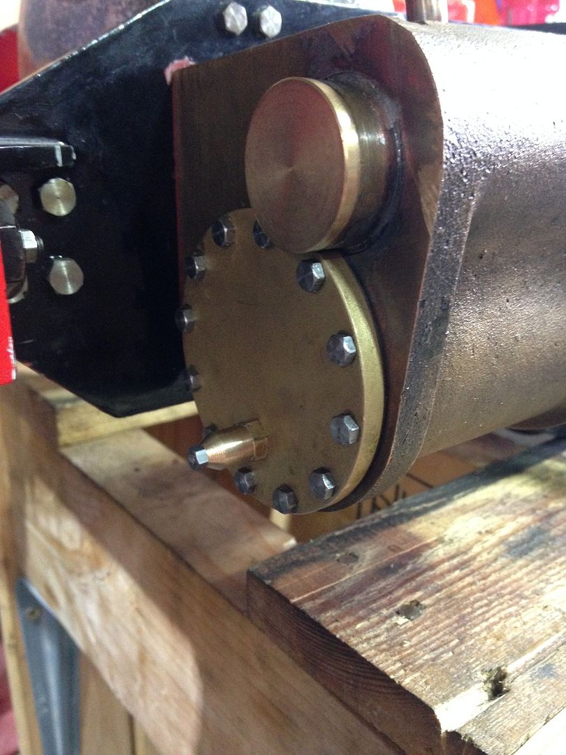 And a final shot of the motion at TDC it shows how little clearance there is on all the parts. 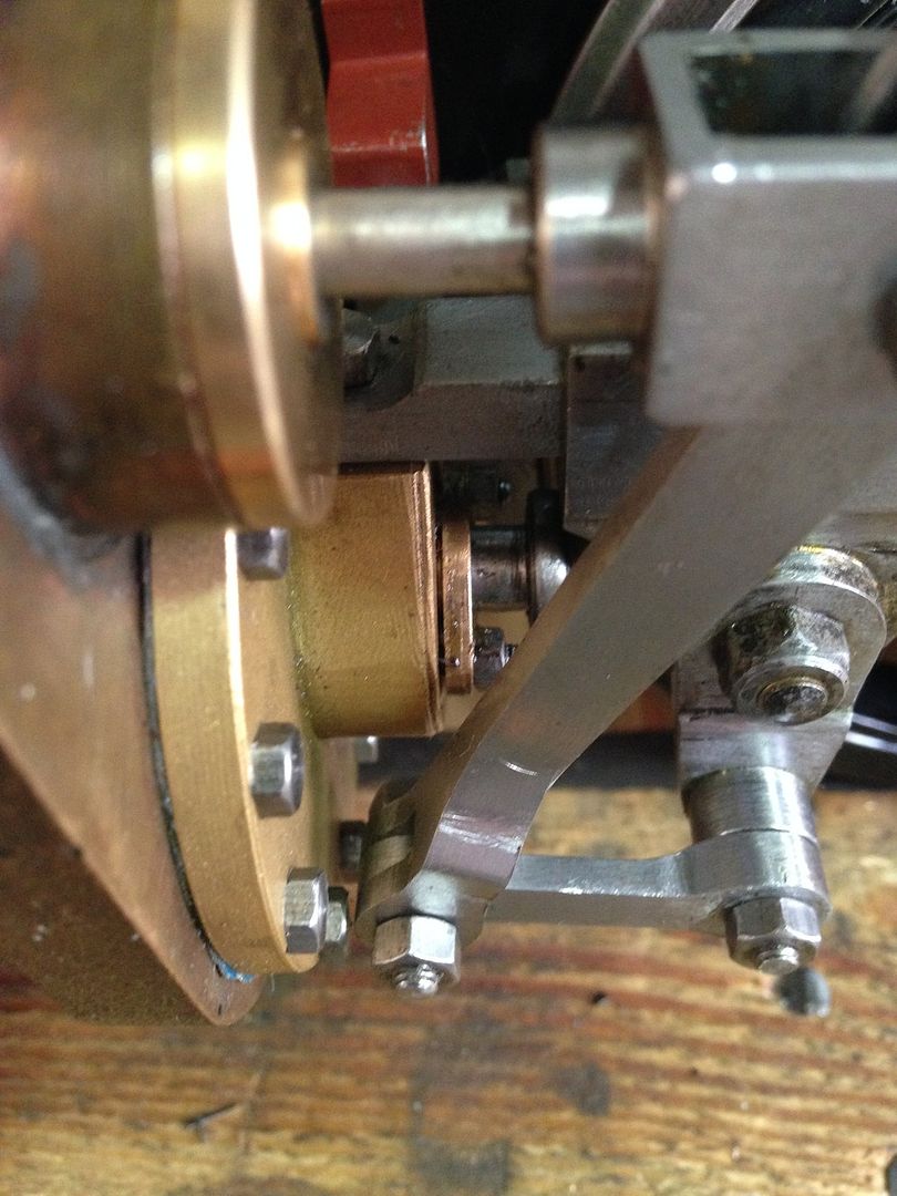 I now have to go back and re do all the machining programs for the cranks I had 4 operations last time so it is going to take a while. I also need to do some work on the mill to get it a bit more reliable as the backlash is becoming excessive and causing problems at turnarounds |
|


