|
|
Post by Doug on Jun 6, 2015 18:34:02 GMT
Ok I have been posting on Rogers speedy thread for about a year now so I thought it about time I started posting on my own thread and stop stealing space off Roger. Anyway I am up to the chassis stage and almost all the parts needed to run on air. So back to my last issue the valve bobbins I had made the bobbins so I could fit PTFE seals on them this is a slight departure from the LBSC design and after trying them I was not happy, in fact all my tests so far with PTFE have ended in failure so I am kinda learning my lesson I think. Unless I can come up with something truly revolutionary then I may as well try and stay conventional with my design choices. The ports on my LBSC design valve liners are just too big to support the PTFE properly so I am back to solid bobbins 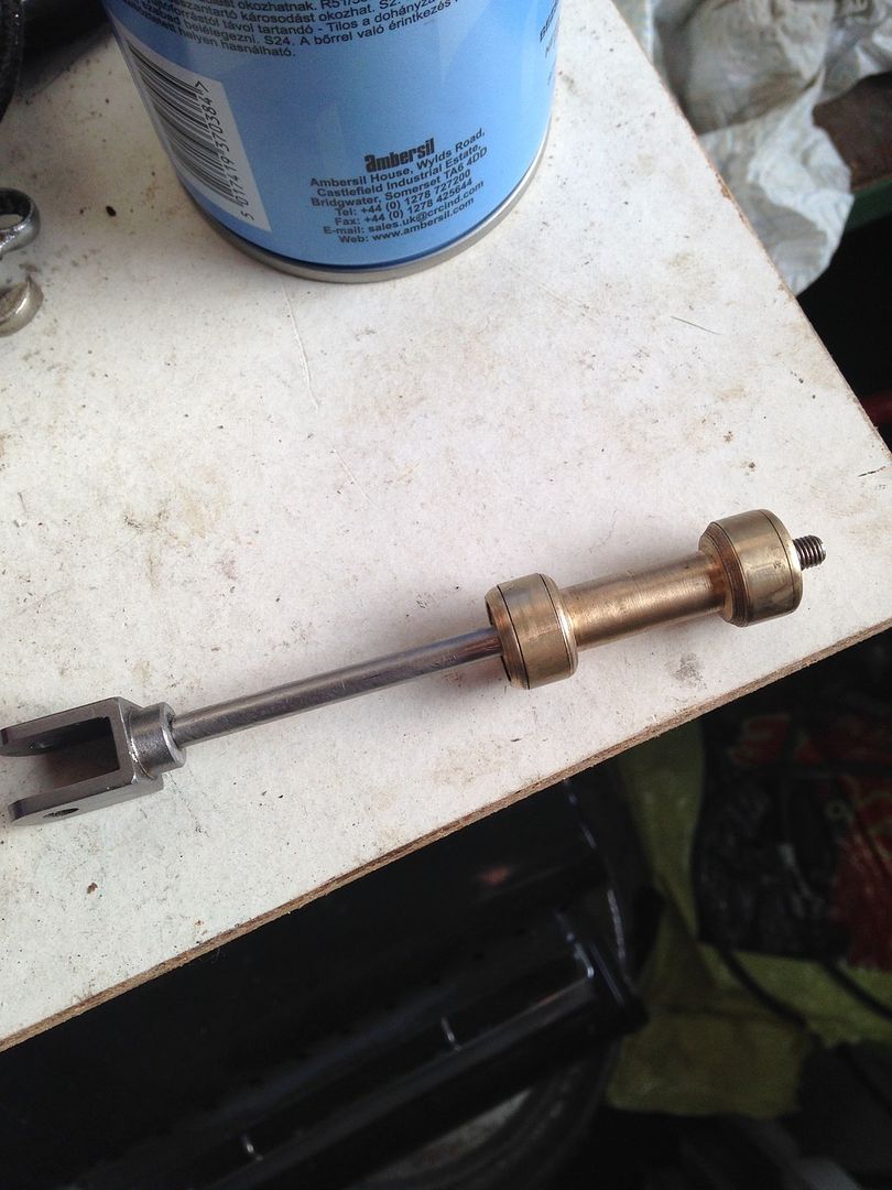 I have tried this bobbin and it's a lovely fit I now need to make some valve spindle covers front and back and I should then just need to make up some pins for all the links 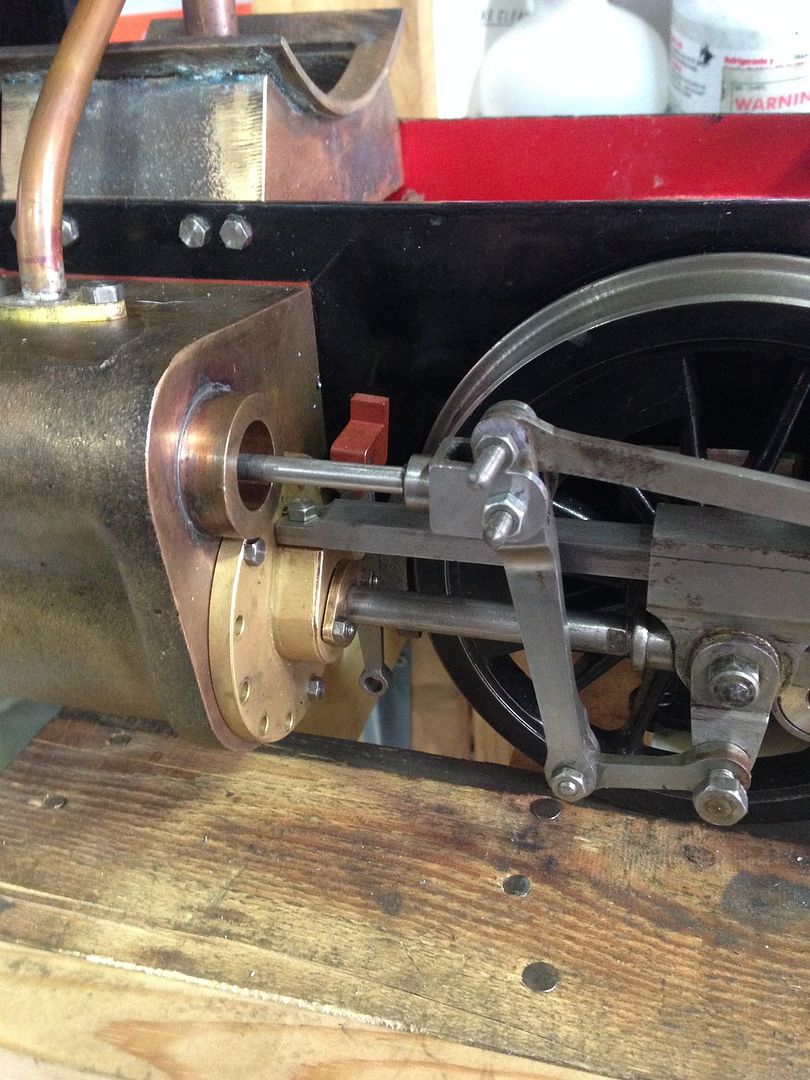 Well that's me for now |
|
|
|
Post by springcrocus on Jun 6, 2015 23:03:37 GMT
It's nice to see another build thread. We all approach the job in hand in different ways, and we all learn from everybody elses methods. In this hobby there is no right way or wrong way, just different ways and the more that we all post the results of our work, whether it's a wondrous success of spectacular failure, we all leave that bit richer for sharing the experience. Great stuff, looking forward to further updates.
Steve
|
|
|
|
Post by runner42 on Jun 7, 2015 1:37:53 GMT
Hi Doug,
a good move to go it alone, but will it slow down Roger's tome of a thread?
I note that you had a problem with the PTFE inserts on your piston valves and you suggested that it was the exhaust ports being the cause. It apparently happened on one only and I was trying to imagine specifically how this happened and I assume that you were operating the sliding motion by hand, (or are you running on air?), either way I intuitively feel that this should not have occurred unless there is something wrong with the exhaust port to cause this. You are in best position to determine the exact cause, I just think that you should satisfy yourself that you understand the reason and that you won't get a premature failure with the alternative inserts.
Brian |
|
|
|
Post by Roger on Jun 7, 2015 7:07:34 GMT
Hi Doug,
a good move to go it alone, but will it slow down Roger's tome of a thread?
I note that you had a problem with the PTFE inserts on your piston valves and you suggested that it was the exhaust ports being the cause. It apparently happened on one only and I was trying to imagine specifically how this happened and I assume that you were operating the sliding motion by hand, (or are you running on air?), either way I intuitively feel that this should not have occurred unless there is something wrong with the exhaust port to cause this. You are in best position to determine the exact cause, I just think that you should satisfy yourself that you understand the reason and that you won't get a premature failure with the alternative inserts.
Brian ... not a chance Brian, it's full steam ahead! I was forgetting that the ports on the LBSC sleeves have only two short bridges, the rest of the port doesn't have anything to support any type of ring or sleeve that's trying to expand into the port. Maybe you'd get away with a much thicker section PTFE ring that's more rigid and less prone to catching the edge of the port? Anyway, a solid bobbin will definitely work, and that's the fall back position for all of us. |
|
|
|
Post by Doug on Jun 7, 2015 8:00:06 GMT
Hi Doug,
a good move to go it alone, but will it slow down Roger's tome of a thread?
I note that you had a problem with the PTFE inserts on your piston valves and you suggested that it was the exhaust ports being the cause. It apparently happened on one only and I was trying to imagine specifically how this happened and I assume that you were operating the sliding motion by hand, (or are you running on air?), either way I intuitively feel that this should not have occurred unless there is something wrong with the exhaust port to cause this. You are in best position to determine the exact cause, I just think that you should satisfy yourself that you understand the reason and that you won't get a premature failure with the alternative inserts.
Brian Hi Brian It's funny I had a really good look last night at the issue ironically the exhaust ports that killed my seal ring don't get passed over in use the seal ring passes over the cylinder port only and admits pressure one side and exhaust on the other however I am worried that as Roger mentioned the expansion will cause this ring to be forced down the other port that it does cross over. The design needs to be a matrix of holes like Rogers rather than a couple of slots like I have. The solid bobbins I now have will work quite well of that I am sure, and if at some point a new material shows itself as suitable I can make a couple of seal rings up and away I go. at least I can be reasonably happy I can move on with the build with confidence |
|
|
|
Post by Roger on Jun 7, 2015 9:58:20 GMT
It sounds like you had the same trouble as I had with the 'O' rings getting shredded by the exhaust port. I rounded off the corners of those since steam has to flow rapidly over them. There's no harm in you doing the same.
|
|
|
|
Post by Doug on Jun 7, 2015 13:10:25 GMT
Some more progress this morning ( my wife left me alone for a couple of hours an amateur mistake) so I decided to get on with the valve rod guides or " valve end caps " First off some 28mm gunmetal as they are basically bearings. 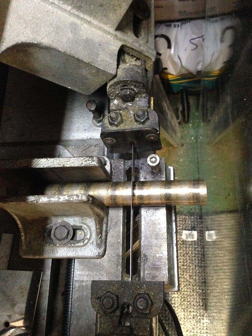 I love this saw it makes very short work of jobs like these Spun it up on the lathe and reamed it 3/16" it has a good 11mm of bearing surface 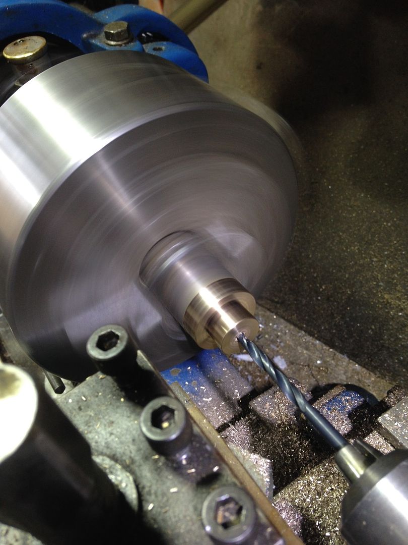 I made these a very good fit 0.01mm so it's a tight fit 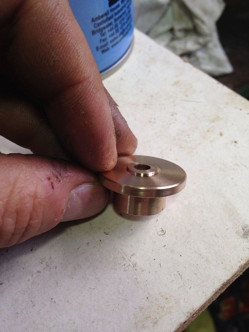 Trial fit 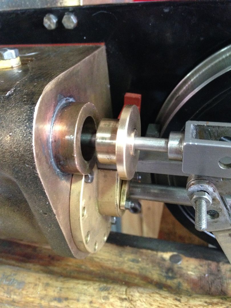 And pushed home 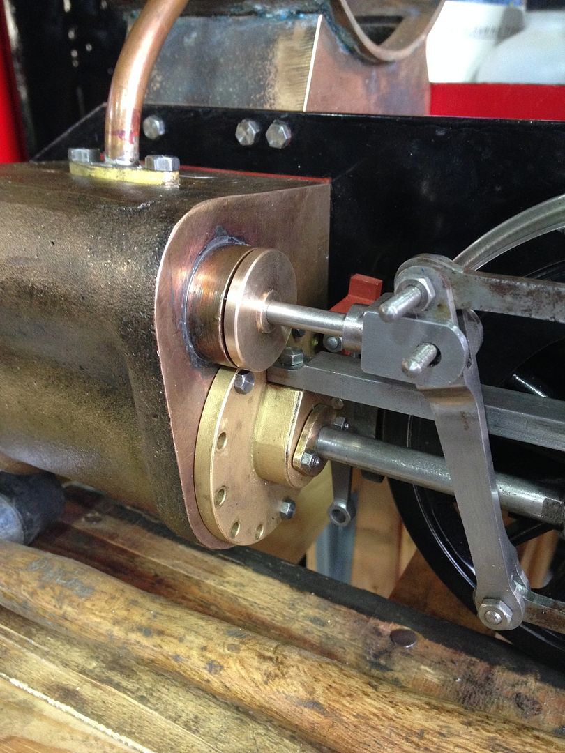 The other cylinder 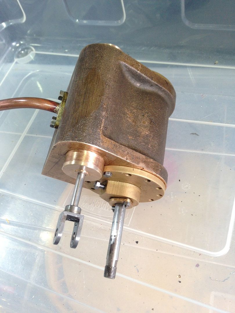 The front ones are just blanks I will add faux guides later as these are a visual detail on the 1500 class 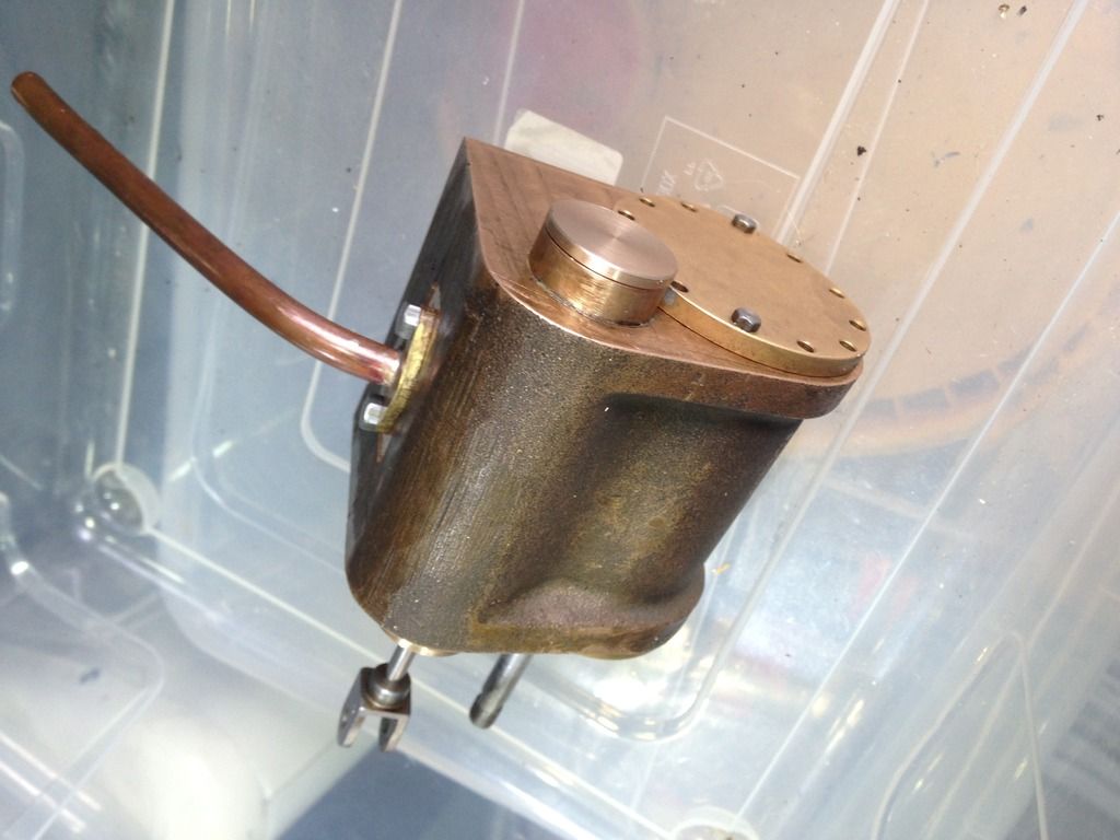 It all seems to seal quite well with the valve bobbin Central the piston sucks back to a central position when moved That's all from me for now |
|
|
|
Post by Roger on Jun 7, 2015 13:48:09 GMT
Very neat Doug, and that's quite a decent length of bearing if the bobbin is going to act as part of the guide too.
|
|
|
|
Post by Doug on Jun 8, 2015 12:50:13 GMT
Very neat Doug, and that's quite a decent length of bearing if the bobbin is going to act as part of the guide too. Hi Roger, i have ended up with a bit of a hybrid the bobbin itself does not/ cannot touch the valve liner walls the only contact is via two rings (now made of brass) these wear rings are a loose fit on the bobbin (bobbin outer dia 14-14.1mm and inner ring dia is 14.2mm)so although not exactly sloppy it has a looseish fit on the inside of the rings the rings have a very good fit in the liner and seal the ports very well. the rings will wear out but at least i can make 4 rings in about an hour on the lathe. it all moves very nicely now the end caps are on it feels like a good hydraulic valve. |
|
|
|
Post by Roger on Jun 8, 2015 13:42:04 GMT
Hi Doug,
I agree that making new rings is very quick, and that's why I'm not bothered about experimenting with different arrangements and fits.
I'm not sure Brass is a good choice of material though, I'm not sure if that will pick up or not. Maybe someone else can guide you on that.
So if I understand you correctly, there's nothing keeping the bobbin central, it's just prevented from moving more than +/-0.05mm? If that's the case, surely the only thing keeping the valve rod straight is the short portion where it passes through the end cap? Maybe I'f got the wrong end of the stick, but if that's the case, it will wear very quickly indeed. You might consider making the valve rod much longer, turn down the diameter to just under the thread size, and use the end cap as a bearing like it is on 1501.
|
|
|
|
Post by Cro on Jun 8, 2015 14:11:35 GMT
Hey Doug, good to see a different approach to the Speedy along side Rogers build, now we can compare you both  Question, have you soft soldered the Valve Liners into the cylinder block? Adam |
|
|
|
Post by joanlluch on Jun 8, 2015 15:23:58 GMT
Hi Roger, as we wait for Doug response, I think he means to support the bobbin by the rings themselves, so it is not the end cap what is keeping the rod straight, if I understand it well. In fact, given that the bobbin has a certain length, the centring of the rod may rely solely on the rings fit against the liner, rather than on the end cap. Also, since the rod does not have any support at the front end I would assume that the rings on the bobbin are not floating, and that's why they can keep the bobbin in place. Of course, Doug will confirm or deny this appreciation.
|
|
|
|
Post by Doug on Jun 8, 2015 15:48:48 GMT
Hi Doug, I agree that making new rings is very quick, and that's why I'm not bothered about experimenting with different arrangements and fits. I'm not sure Brass is a good choice of material though, I'm not sure if that will pick up or not. Maybe someone else can guide you on that. So if I understand you correctly, there's nothing keeping the bobbin central, it's just prevented from moving more than +/-0.05mm? If that's the case, surely the only thing keeping the valve rod straight is the short portion where it passes through the end cap? Maybe I'f got the wrong end of the stick, but if that's the case, it will wear very quickly indeed. You might consider making the valve rod much longer, turn down the diameter to just under the thread size, and use the end cap as a bearing like it is on 1501. hi roger i think you have the concept bang on as i read it, however i dont understand where any lateral force will come in the only force acting on the rod is forwards and backwardsthe only thing that can wear out is the ring, i cant see this picking up as its the same material combination as i have on my slide valves on butch i doubt it needs the extra support as it is essentially the same as the LBSC design which too is only supported at one end and the bobbin is floating between a couple of lock nuts. should work (i hope) |
|
|
|
Post by Doug on Jun 8, 2015 15:54:31 GMT
Hey Doug, good to see a different approach to the Speedy along side Rogers build, now we can compare you both Question, have you soft soldered the Valve Liners into the cylinder block? Adam bit oddly i have used two types of fixing on this. One cylinder had the casting centers off center, so i had to use a 28mm dia valve liner to get it in the correct position (turned down to 1" on the ends to look like the other one) this is soft soldered in. I didnt like the experiance much as keeping the flux going for long enough was a bit hard because of the size of the casting. So for the 1" liner in the other side i slid in and used Loctite 620 (the high temp one) both are sealed up a treat if i was to do it again i would recomend the Loctite every time however it does go off VERY quickly so its essential to get it in position within a second or two. 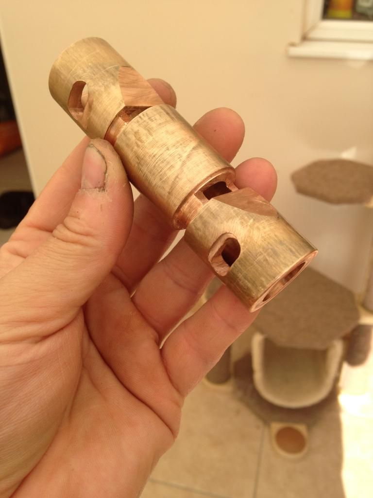 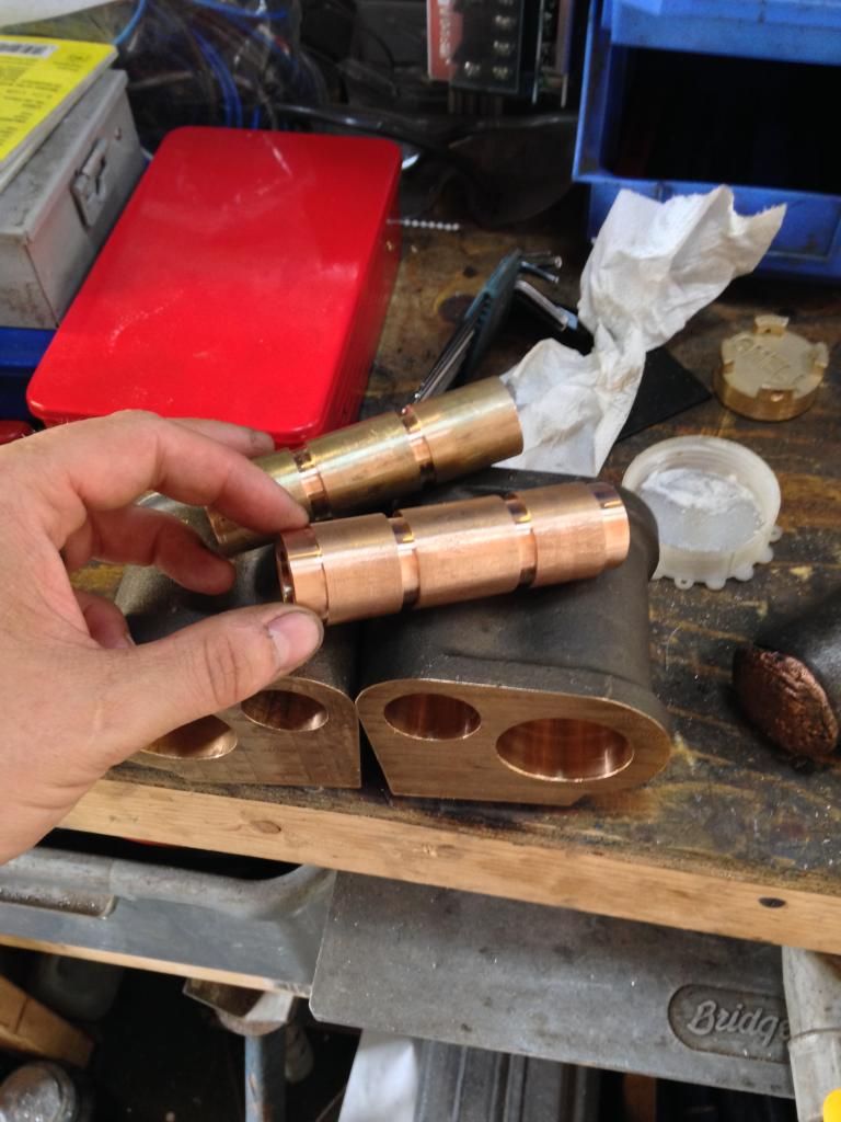 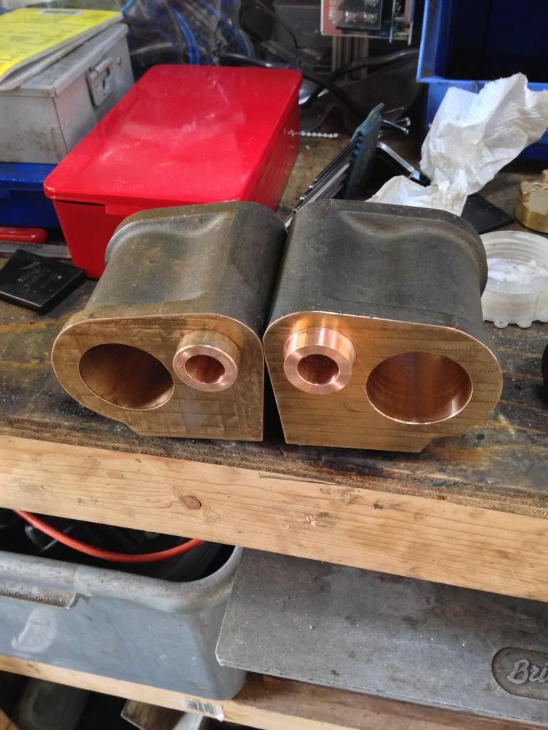 |
|
|
|
Post by Roger on Jun 8, 2015 16:09:50 GMT
Hi Doug, I agree that making new rings is very quick, and that's why I'm not bothered about experimenting with different arrangements and fits. I'm not sure Brass is a good choice of material though, I'm not sure if that will pick up or not. Maybe someone else can guide you on that. So if I understand you correctly, there's nothing keeping the bobbin central, it's just prevented from moving more than +/-0.05mm? If that's the case, surely the only thing keeping the valve rod straight is the short portion where it passes through the end cap? Maybe I'f got the wrong end of the stick, but if that's the case, it will wear very quickly indeed. You might consider making the valve rod much longer, turn down the diameter to just under the thread size, and use the end cap as a bearing like it is on 1501. hi roger i think you have the concept bang on as i read it, however i dont understand where any lateral force will come in the only force acting on the rod is forwards and backwardsthe only thing that can wear out is the ring, i cant see this picking up as its the same material combination as i have on my slide valves on butch i doubt it needs the extra support as it is essentially the same as the LBSC design which too is only supported at one end and the bobbin is floating between a couple of lock nuts. should work (i hope) Hi Doug, There are up and down forces being transmitted by the radius rod because the joint at the expansion link end is either above or below the centre line depending on whether it's in forward or reverse gear. I don't believe the LBSC design is intended to allow the bobbin to float on the shaft, it's surely clamped up tight? As I understand it, the solid piston valve spool is part of the bearing so I don't think it's the same at all. I think you're going to need something to either centre the piston rings, say 'O' rings under them, or support the other end of the valve rod else it's going to waggle up and down. Maybe someone who knows these locomotives can tell us whether the spool is floating or fixed to the valve rod. |
|
|
|
Post by Cro on Jun 8, 2015 16:16:44 GMT
Doug, I see....I think...! So the center in the cylinder block was out so you bored it off center meaning you had to go large on the diameter? I think that's how I read it but still a little lost as to the soft soldering. I know how much of a pain liners can be to seal in place after F***ing around with the 9f ones (don't get me started on those) and yes loctite, especially new stuff, can go off very quickly (having a pot of the old stuff always comes in handy for these types of jobs) but I feel using soft solder would be even worse to use as you can't ensure that it has flown all the way in and sealed where you want it, I'm not saying you can with loctite either but I would have thought it easier that way. Interesting, was just curious as to why  Also Roger with regards to the bobbins and the valve rod, I haven't read the conversations fully but from what I understand are you saying that the bobbins should be fixed solid on the valve spindle (irrelevant of how the bobbin has been made)? Adam |
|
|
|
Post by Roger on Jun 8, 2015 16:38:25 GMT
Hi Adam,
I'm of the opinion that the bobbin ought to be solidly attached to the shaft else it can't contribute anything to resisting the up and down forces on the end of it. If all you're relying on to guide it straight is the short length where the rod passes through the end cap, I can't see that being good enough. If, however, you have either a solid bobbin rigidly attached to the valve rod, or, as in my case, the bobbin rigidly attached to the rod and 'O' rings pressing against the piston rings to centre it, then you're getting much more support.
I thought the solid LBSC design had those lock nuts just to allow for the bobbin to be adjusted along the rod, not to allow it to float?
|
|
|
|
Post by Cro on Jun 8, 2015 17:49:21 GMT
Ok so the way I have been taught to have it my a range of people is to have a thou or 2 at most float of the bobbin on the valve rod, this allows the bobbin to essentially float within the bore and not affected by the movement of the valve rod its self as the motion work will cause the rod to not always run true and concentric within the bore. I haven't seen any LBSC drawings to see how he has drawn it but the way I have the 9f and the way the '5' is when I got it apart yesterday is there is a rear locking nut to set the position of the bobbin on the rod and the front PAIR or locking nuts lock against each other allowing this 1 or 2 thou play along to the rod.
Baring in mine most holes through bobbins are not a clearance hole on the valve rod but significantly larger if you were to lock the bobbin up on the rod and it were not dead center you would get some pretty bad and uneven wear in that bore.
This is just what I have been taught as typical practice and what I have found in grandads locos too so I trust that advice, if you consider a slide valve loco, the valves themselves are only a snug fit on the buckle being guided along the surface rather than fixed to the valve rod.
Adam
|
|
|
|
Post by Roger on Jun 8, 2015 17:53:31 GMT
Thanks for that Adam, I'm really surprised. I guess it's done that way because the fit in the sleeve is so close that the slightest misalignment would cause it to bind up. That doesn't leave much bearing length to support the shaft though, it's no wonder they wear out quite quickly.
|
|
|
|
Post by Cro on Jun 8, 2015 18:00:28 GMT
Yeah but you say that....I measured up the 5's ones when we got them out, they have been in I think around 10 years if not more, the loco is ran weekly throughout the season and they are both down 2 thou on the size they were made to when they were last done on a 45 year old engine, yet to check what the bore size now is but you'd be surprised how well they do last!
|
|


