|
|
Post by Roger on Aug 27, 2015 21:48:52 GMT
Looking good Doug, but I'm staggered at the run time though, that seems very long.
What cutter diameter, feed, spindle speed and depth of cut are you using?
|
|
|
|
Post by Doug on Aug 28, 2015 5:09:23 GMT
Looking good Doug, but I'm staggered at the run time though, that seems very long. What cutter diameter, feed, spindle speed and depth of cut are you using? I ran a six mm cutter 8mm/min 400rpm and a 0.25mm depth a 1mm stepover on the roughing 10mm deep leaving 0.1 for a finishing pass that ran at same speed and feed but at 0.5mm depth. then four drill routines for the holes (the blind ones were slot drilled with two sizes and all others were spotted with a centre drill. I tried to cut deeper but the mill is woefully lacking in rigidity so it just jumps about and becomes unstable. i have just had a Sieg X3 at work and I am thinking I will get one of those in a few years as its one heck of an upgrade. i just have to work within the limits of my X1L I wouldn't have bought it after what I know now it's really only useful as an accurate drilling MC |
|
|
|
Post by Roger on Aug 28, 2015 5:59:26 GMT
Thanks for that Doug, I presume you've tried many combinations of feeds and speeds to find the best metal removal rate. In the end, rigidity is everything in this game so I can see why you're lusting after something with more 'meat' on it.
Still, it's an awful lot more useful than it was pre-CNC and you can still coax a nice job from it.
|
|
|
|
Post by Doug on Aug 28, 2015 7:48:08 GMT
Thanks for that Doug, I presume you've tried many combinations of feeds and speeds to find the best metal removal rate. In the end, rigidity is everything in this game so I can see why you're lusting after something with more 'meat' on it. Still, it's an awful lot more useful than it was pre-CNC and you can still coax a nice job from it. thats very true when i used it pre CNC it was just hopeless it took just as long but doing it manually it was very easy to fall asleep at the wheels  now at least i can let it do its thing and it gets there in the end, with only a cusery check every hour or so. I am getting awsome results on the small jobs though the four pockets in the pic are 0.75mm deep and are orbited with one of those 3.1mm carbide pcb slot drills you recomended a while back they came out really well and acurate too. |
|
|
|
Post by Roger on Aug 28, 2015 9:53:01 GMT
You've also added a lot of value to the machine, I bet you'll get a good price for it when you upgrade.
At the moment I'm slowly 3D machining the brake hangers, and on jobs like that, there's no benefit to having a rigid machine.
PCB slot drills aren't that robust but they are razor sharp and so cheap that they are a useful addition to your tool arsenal. It would be very interesting to see how your machine gets on with something like a 5mm carbide ripper. I can't seem to find them any smaller than that, ideally I'd like to find some 4mm ones.
|
|
|
|
Post by Doug on Aug 28, 2015 10:51:08 GMT
You've also added a lot of value to the machine, I bet you'll get a good price for it when you upgrade. At the moment I'm slowly 3D machining the brake hangers, and on jobs like that, there's no benefit to having a rigid machine. PCB slot drills aren't that robust but they are razor sharp and so cheap that they are a useful addition to your tool arsenal. It would be very interesting to see how your machine gets on with something like a 5mm carbide ripper. I can't seem to find them any smaller than that, ideally I'd like to find some 4mm ones. I have a 6mm Ripper it's amazing on aluminium but a bit pointless on hard steel it just bounces off like the other cutters causing me to go light and slow so there is little or no benefit. |
|
|
|
Post by Doug on Aug 29, 2015 20:34:36 GMT
Quite a bit of tidying to do but I have the first crank done  |
|
|
|
Post by Doug on Sept 6, 2015 15:48:24 GMT
Ok some progress again now I have fixed my milling machine  got the first return crank properly fitted with mini bolts and a taper pin all dialled in.  And then I got to run it on air Properly happy with the result and this is just one side running looking forward to having two cylinders  |
|
|
|
Post by springcrocus on Sept 6, 2015 17:01:04 GMT
Well done, Doug. It's always satisfying when ones efforts start to pay off. Well pleased for you. Steve |
|
|
|
Post by Roger on Sept 6, 2015 20:28:22 GMT
Excellent! How good it that!
|
|
|
|
Post by Doug on Sept 6, 2015 20:32:48 GMT
Proper happy with the result. I am a bit unsure how I am going to set the valve up tho going to have to look in my books for a method, it runs well so I know I am not too far off but I can "feel" that its a tiny bit off
|
|
|
|
Post by donashton on Sept 6, 2015 20:37:36 GMT
Hi Doug,
Bet you feel good right now, and deservedly so.
Should spur you on to beat Roger! He-He.
Don.
|
|
|
|
Post by Doug on Sept 6, 2015 20:47:38 GMT
Hi Doug, Bet you feel good right now, and deservedly so. Should spur you on to beat Roger! He-He. Don. Hi Don this is one race I can never win it has been 45 years and four generations so far in the making this may make the prize for longest build ever. Least I hope to get it finally finished in a timely manner "on my watch" I have a really nice project I want to get onto once the "daily runner" is finished. |
|
|
|
Post by Roger on Sept 6, 2015 20:50:02 GMT
We'll have to make a date for a 'Double Header' when we're both finished.
If you mark TDC on any of the wheels as accurately as you can, you can put it in full gear, open the drain cocks and use low pressure air to indicate when the port opens. You can mark the point on the wheel for the front and back cylinder and they ought to be the same distance before TDC or BDC. That's all I did, then adjust it until they are equal.
|
|
jma1009
Elder Statesman

Posts: 5,901
|
Post by jma1009 on Sept 6, 2015 21:17:57 GMT
hi doug,
very well done! quite a severe test that - just one side! i do the same to my own at that stage.
yes, as Don suggests i can see a race to the finish here!!
copper and silver solder on order for the boiler?
cheers,
julian
|
|
|
|
Post by Doug on Sept 9, 2015 21:09:11 GMT
With a bit of measuring and generally considered thought I have come up with a drawing for my Eccentric Rods it puts the important bits where they should be and still retains a roughly similar appearance to the original.  Now thanks to Rogers build photos I can replicate the cutting methods on my CNC. |
|
|
|
Post by Roger on Sept 9, 2015 21:30:17 GMT
Excellent, but I don't think that's the Radius Rod... isn't that the Eccentric Rod? I look forward to seeing that being machined.
|
|
|
|
Post by Doug on Sept 10, 2015 6:20:18 GMT
Excellent, but I don't think that's the Radius Rod... isn't that the Eccentric Rod? I look forward to seeing that being machined. haha very true I have no idea what I was doing when I wrote that |
|
|
|
Post by Doug on Sept 20, 2015 19:11:50 GMT
Some more progress, the eccentric rod was setup on the mill my first attempt ended in a big crash resulting in a broken cutter and a vice that got pushed across the table, Whoops! Anyway not deterred I altered the CAM output to a more aggressive cutting routine to reduce the cycle time by quite a bit. the surface finish suffered a bit but it ran all the way through on the second attempt. The first operation to mill the profile 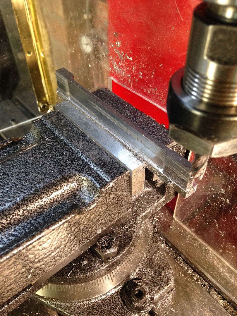 Then setup on my jig to cut the side profile surprisingly most of this bar will be thrown as the Rod is quite slender 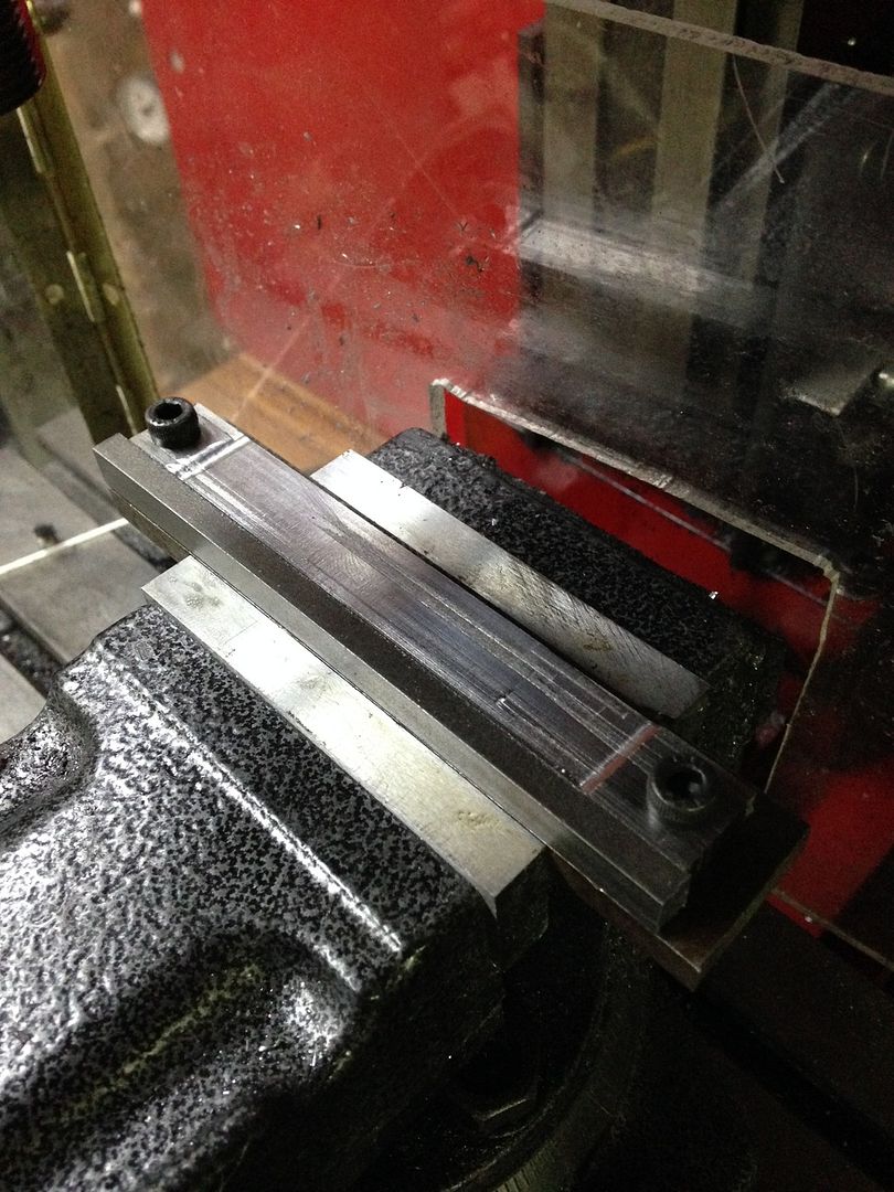 Just need to run this program and then clean it up a bit. |
|
|
|
Post by Roger on Sept 20, 2015 19:35:05 GMT
Excellent, it's such an easy way to make these so long as you don't crash it! I created a beautiful rod profile, but somehow managed to include the big end hole in that, so it finished the outside nicely before knocking seven bells out of the end with a 16mm ripper.... Oh well, that's how we learn.
I take it the mill is much more capable now then?
|
|


 now at least i can let it do its thing and it gets there in the end, with only a cusery check every hour or so. I am getting awsome results on the small jobs though the four pockets in the pic are 0.75mm deep and are orbited with one of those 3.1mm carbide pcb slot drills you recomended a while back they came out really well and acurate too.


