|
|
Post by Roger on Aug 10, 2015 7:37:57 GMT
I like that little chuck you have for the mill, I really ought to make a proper backplate for the 3 jaw I use occasionally. I'm sure you'll sort out the mill easily enough. It's annoying though when it's all set up and it goes pear shaped like that.
Boy, that's mighty close at TDC, still, a miss is as good as a mile so it doesn't matter.
I'm going to have to tackle those relief valves too. Did you guess the dimensions or have you got drawings?
|
|
|
|
Post by Doug on Aug 10, 2015 14:59:20 GMT
I like that little chuck you have for the mill, I really ought to make a proper backplate for the 3 jaw I use occasionally. I'm sure you'll sort out the mill easily enough. It's annoying though when it's all set up and it goes pear shaped like that. Boy, that's mighty close at TDC, still, a miss is as good as a mile so it doesn't matter. I'm going to have to tackle those relief valves too. Did you guess the dimensions or have you got drawings? that chuck is very handy indeed infact i am getting a 3 jaw one too so i dont have to keep centering up on the 4 jaw. the mill turned out to be the anti backlash screw in the delrin nut that had come loose it now seems to be fairly good with just 0.045mm of backlash comp. the valves are a guess from photo's i have of 6990 Witherslack Hall. its going to be a personal challenge to get my rotory table setup and mill the pockets in them, should be fun. |
|
|
|
Post by Roger on Aug 10, 2015 15:04:02 GMT
I find the 3-jaw very useful for repeat jobs, it certainly saves time. Good news about the leadscrew then.
I think that's what I'm going to do too with the valves. I've already had a go at it and they don't look too bad. You may need to make a mandrel to screw them into so you can reach those slots when the chuck jaws are in the way.
|
|
|
|
Post by Doug on Aug 16, 2015 10:31:18 GMT
Ok now I have my mill back up and running correctly I have been able to re write the programs for the return cranks. The bar has been set really high by Roger so I am going off plan a bit to make them look more 1501 less Speedy. i am currently running the mill making the blanks for the cranks.  These look alot better than my first effort |
|
|
|
Post by Roger on Aug 16, 2015 11:51:54 GMT
'Two parts on a stick', a new twist! You're getting a nice finish there Doug. Did you nest them in the software or just turn the bar round? I'd still part them off, even are they are, is that the way you usually do it? I leave about 0.2mm on if they need cleaning up.
|
|
|
|
Post by Doug on Aug 16, 2015 12:37:19 GMT
'Two parts on a stick', a new twist! You're getting a nice finish there Doug. Did you nest them in the software or just turn the bar round? I'd still part them off, even are they are, is that the way you usually do it? I leave about 0.2mm on if they need cleaning up. I mirrored them in the CAD stage because the last one I did I noticed that there would be enough stock to make the two together. That top surface will become the backs, I have a 3/8" blind hole and a 3/16" through hole to put in them both, and then I am going to band saw them off. I then intend to make a jig to hold them while I machine the fronts. i can't part off 2.5" bar I don't have the tooling or a lathe big enough. The finish is mostly because of the cutter the one I am using currently is a v expensive one £21 ish for 6mm the top surface was done with a 12mm one that cost me £43 they are for much harder materials and we use this type at work for cutting RollsRoyce Ardor engine vanes so I know they can take some stick. |
|
|
|
Post by Roger on Aug 16, 2015 13:38:48 GMT
Ah, I see. That's something I've not done before. I wrote a little utility program that all my CAM outputs get put through so I can manipulate the G-Code if necessary. One function intercepts commands I put in the comments so that it generates an array of images which is sometimes handy when I'm making lots of the same parts out of a sheet of material.
That's fiddly to hold without a pocket, at least that's easy to machine and it doesn't have to be that deep.
I'm very impressed with those cutters I bought through Alibaba, they seem to be very good quality and much cheaper than buying through UK suppliers. The only problem is that you need to be able to buy enough to make it worthwhile and that's a lot of expense in one go.
|
|
|
|
Post by Doug on Aug 16, 2015 14:14:05 GMT
Ah, I see. That's something I've not done before. I wrote a little utility program that all my CAM outputs get put through so I can manipulate the G-Code if necessary. One function intercepts commands I put in the comments so that it generates an array of images which is sometimes handy when I'm making lots of the same parts out of a sheet of material. That's fiddly to hold without a pocket, at least that's easy to machine and it doesn't have to be that deep. I'm very impressed with those cutters I bought through Alibaba, they seem to be very good quality and much cheaper than buying through UK suppliers. The only problem is that you need to be able to buy enough to make it worthwhile and that's a lot of expense in one go. I just bought two new cutters from Cutwel cost me £15 they have a k2 coating which should make them last a good while esp with the light weight use I will be giving them. Ed sent me a link for some rather snazzy slot drills that look pretty good so I may be buying one of those next. anyway finished the crank blanks and they fit a treat so I just need to make a jig to hold them for the next few opp's and when I have finished them I should have all the parts I need to do an air test and set all the valve gear up.  |
|
|
|
Post by Roger on Aug 16, 2015 14:18:56 GMT
I used to buy all my cutters from them, I still have plenty including the type you mention and they're very good. They do sometimes have a sale of 3 for 2 on cutters but they wouldn't repeat that on Rippers, that's why I decided to go elsewhere. Having said that, for buying just one or two cutters they can only be beaten by the odd one found on eBay.
So how are you holding the cranks onto the crank pin?
|
|
|
|
Post by Doug on Aug 16, 2015 14:55:20 GMT
I used to buy all my cutters from them, I still have plenty including the type you mention and they're very good. They do sometimes have a sale of 3 for 2 on cutters but they wouldn't repeat that on Rippers, that's why I decided to go elsewhere. Having said that, for buying just one or two cutters they can only be beaten by the odd one found on eBay. So how are you holding the cranks onto the crank pin? I would like to say I have this covered but I really haven't made my mind up but I really like,
Jim's method
|
|
|
|
Post by Roger on Aug 16, 2015 16:05:44 GMT
That's certainly a neat way of doing it. The tricky thing with any of these methods is getting it at the right angle. I've used dead reckoning and hope will be good enough. It's not easy to measure on the locomotive so I decided it was easy enough to make another return crank with the new angle on it if the angle was wrong.
|
|
|
|
Post by Doug on Aug 16, 2015 16:36:02 GMT
That's certainly a neat way of doing it. The tricky thing with any of these methods is getting it at the right angle. I've used dead reckoning and hope will be good enough. It's not easy to measure on the locomotive so I decided it was easy enough to make another return crank with the new angle on it if the angle was wrong. LBSC's book is quite good in that regard it tells you exactly how to set the angle, it's really easy using that method. a paresis would be you get the radius rod in a neutral position (disconnected from the lifting arm it can be raised and lowered without pulling or pushing the valve spindle) affix the radius rod position so I can't move then push the loco to TDC forward Set the return crank vertical and measure distance between hole centres now roll to TDC back other end of the stroke and the centre distance should be the same if not move half the distance and repeat, keep doing this till the distances are equal. Then by jingo it should be the right position. least that's how I read it. |
|
|
|
Post by Roger on Aug 16, 2015 17:26:23 GMT
That sounds simple enough. I've got lots still to check and still a few more parts to complete but then it's time to see if it's a Steam Engine or a Door Stop.
|
|
|
|
Post by Doug on Aug 23, 2015 19:30:03 GMT
OMFG aaaaaaaaaahhhhhhhhhhhh nuts!!!!! I have spent a week making my return cranks and now I have found they are the wrong size. i made a nice fixture that I can hopefully use for the larger cranks  And the almost finished article it's going to be the nicest bit of scrap metal I have ever made 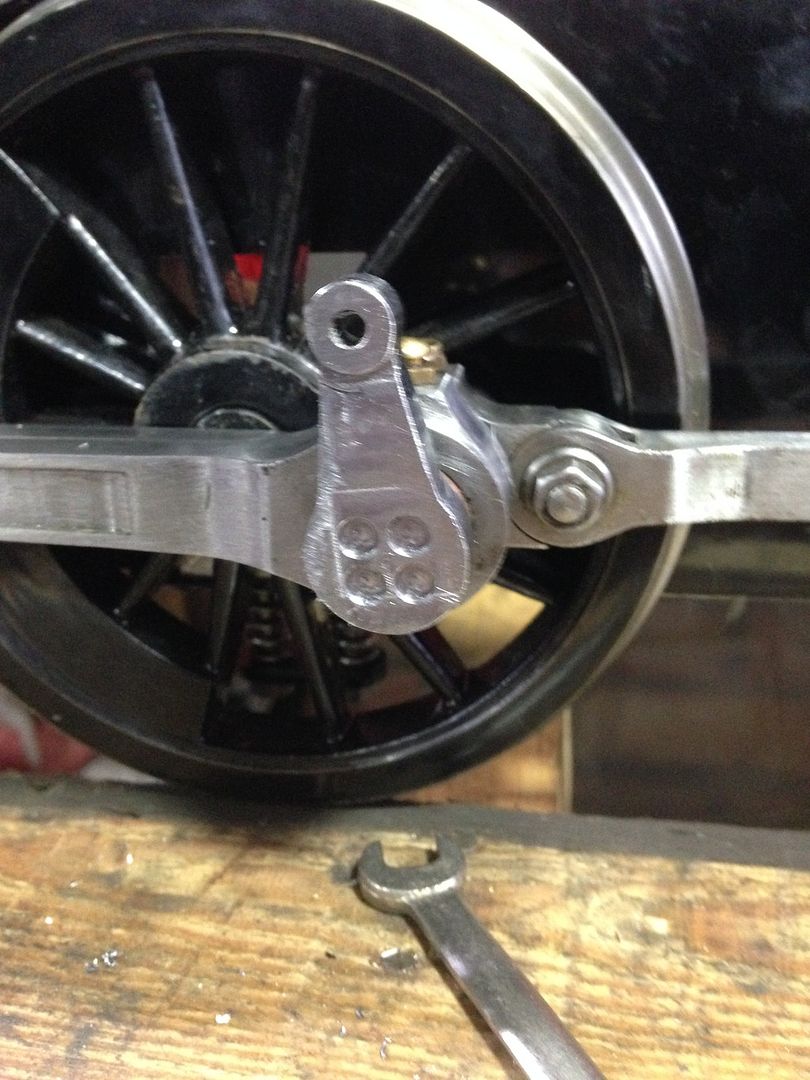 I am going to be in the corner crying to myself for a bit, where did I put that whiskey.  |
|
|
|
Post by Doug on Aug 23, 2015 19:38:28 GMT
Ok next question what size is it between centres? 1 3/16" or 1 5/16"?  |
|
|
|
Post by Roger on Aug 23, 2015 20:08:07 GMT
Hi Doug, Take a look at this temporary link, I'm pretty confident you should be using 1-5/16" because that's the return crank length in the simulator for ORIGINAL SPEEDY that I have. Sorry to hear your woes, but when you sober up after your Whiskey, you'll make an even finer job of it! |
|
|
|
Post by Deleted on Aug 23, 2015 20:18:35 GMT
Hi Doug In situations like this when dimensions aren't clear I measure the actual distance on the plan, I will also measure a dimension that is clear to see, for example the thickness of the crank at 3/16. If the drawing is to scale ( a rare occurrence) then you can just use the measure as shown by your rule on the drawing. If the drawing is not to scale then work out it's scale first, you may find this easier in metric...so for the 3/16 thickness or 4.76 mm measure the actual size on the drawing and divide that by the measure stated, ie 4.76 this will give you the ratio that the drawing is out by. You can now measure any part you need and multiply it by the ratio that the drawing is out by to give you the measurement that you need...hope I've described this properly....it's easier to check that your doing things correctly if you have the drawing in front of you, well it is for me...  Pete |
|
|
|
Post by Doug on Aug 23, 2015 20:47:20 GMT
Hi Doug, Take a look at this temporary link, I'm pretty confident you should be using 1-5/16" because that's the return crank length in the simulator for ORIGINAL SPEEDY that I have. Sorry to hear your woes, but when you sober up after your Whiskey, you'll make an even finer job of it! Thanks Roger least I have a good setup now for making them and a nice method of fixing the crank too. Stupid plans, at least next time when I build my bullied I will have the whole thing in 3d cad first. |
|
|
|
Post by Roger on Aug 23, 2015 20:49:27 GMT
Hi Doug, Take a look at this temporary link, I'm pretty confident you should be using 1-5/16" because that's the return crank length in the simulator for ORIGINAL SPEEDY that I have. Sorry to hear your woes, but when you sober up after your Whiskey, you'll make an even finer job of it! Thanks Roger least I have a good setup now for making them and a nice method of fixing the crank too. Stupid plans, at least next time when I build my bullied I will have the whole thing in 3d cad first. Exactly, making another one is nothing like as bad as starting from scratch. It's still annoying though. |
|
|
|
Post by Doug on Aug 27, 2015 21:30:48 GMT
Ok so another 14hours on the mill and a new pair of blanks have come off ready for detailing and finishing, I have put them next to the old ones to show how much bigger they are. the backs, all complete  The fronts still to machine they should look something like a standard GWR loco but not quite the plates on 1501 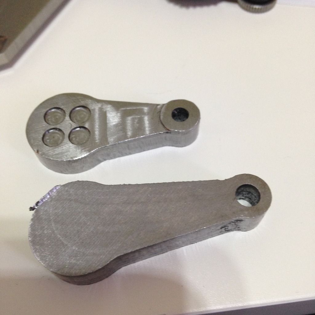 |
|


