|
|
Post by Oily Rag on Jul 9, 2017 8:54:54 GMT
Firstly I must say that I know very little about valve gear, but a few things I've found it might be worth mentioning. Don Ashton is the expert on these matters and you might like to contact him. He's not been well though, so don't expect instant answers. The first thought is that Walschaerts valve gear is, in my opinion, a ghastly bodge, not the improvement over other gears I assumed it to be. It only achieved the level of acceptance because it's easy to maintain. The events won't be the same in forward and reverse, that's simply not possible. Secondly, if you change one dimension, everything else is changed to some degree or other. I'm not sure why your simulator requires so much information, the one Don Ashton showed me only needs the bare minimum. You can download that, but I'm not home at the moment to be able to tell you where from. You can see the output of it for my locomotive in the valve gear section of the wiki that I started if you Google "Building LBSCs SPEEDY". I've tried to explain the events as I understand them from the diagrams the simulator output. Don Ashton reworked the SPEEDY valve gear and published a dimensioned line drawing for the critical dimensions. That was all that was needed to then flesh out the required parts. Another thing I learned was that you need a long cut off to guarantee starting on a two cylinder locomotive, regardless of where it stops. If you had 50% cut off, that would leave the opposite cylinder on TDC, so you could get stuck. So although 60% cut off sounds like a lot, it isn't. Wear on valve gear will reduce the cut off over time, so a generous cut off to start with is helpful. I don't know how to go about designing the valve gear, so I can't really help with that. I just wanted to point out that the idea of a "theoretical setup" is not an idealised one. It's all a compromise. I believe you can achieve acceptable valve events from a range of different geometries, but getting them to be in sensible proportions so they look right and work on your locomotive is something else. Excessive movement will occur with some of the arrangements, and those may not be practical. On mine, it's difficult to get the required clearance between the expansion link and other parts of the mechanism when it's notched back. The geometry on mine ended up with it not being like the full sized locomotive, the crosshead has an extension to move the connection to the union link down considerably. For me, it's more important that it works well than it looks precisely to scale. I'm sorry if this muddies the water even further! Rodger, I appreciate your reply. Regards the compromise, I did mention " I have no understanding of what compromises the valve gear must or can have." The Dockstrader simulator is good for inputs of all the valve and piston dimensions and the pivots. The program is clunky by contemporary standards but it has all the motions, indicator diagrams etc. But I end up a depressed mess when I try to get all to be be reasonable sweet. After some hours of alterations and frustrations I want to go off and slash my wrists. I feel a deplorable failure. I attacked all this many months a go and revisted again these last few weeks. I need to sit on the phone, I can call any where to a land line in the UK, or USA for no extra on my phone internet plan. I need to go in step with lessons with a master. If there was a course for this stuff I would sign up. I have heard so many for 30 years say, do this and a bit of that but it was obvious they were having a bet both ways while stabbing in the dark while tossing a pinch of salt over their shoulder while reading the owl entrails. I don't know of any one in Australia that sorts this from fresh. There must be some one ? I have tried to contact the Author of "Steam Trains on your Garden" but all leads are dead ends. Even the chaps at the heritage workshops, they follow the original drawings thaet were done 70 to 90 years ago. Oh well. I will keep on plugging away and also pluck up the couarage to contact Don Ashton. I don't want to annoy the good man, he must get many pleas for help. Cheers D |
|
Lisa
Statesman
 
Posts: 806 
|
Post by Lisa on Jul 9, 2017 11:22:52 GMT
If you can get in touch with Kenny Saunders (Bribie MELSA), he might be able to help some, or at least be able to point you in the right direction; I know he's designed walschaerts from scratch a couple of times.
As I recall he built a loco with different valve gear on each side once, just to compare the two.
|
|
jma1009
Elder Statesman
  
Posts: 5,922
|
Post by jma1009 on Jul 9, 2017 11:31:49 GMT
Hi Darrell,
I am very pleased that you want to get to grips with Walschaerts valve gear.
I can see that your main motivation is the lack of certain dimensions on the drawings for 'Eric' and dimensions that are not missing but appear to be wrong.
Before playing around with a computer simulator for valve gears, especially where there is a question mark over whether you have all the dimensions and info required, I think it is best to first go back to basics and go through everything stage by stage.
In this respect I prefer to construct a proper fully dimensioned drawing of the side elevation and the plan. As you draw and dimension each section everything should fall into place if done in the right order starting first with the valve dimensions and the port dimensions.
As your model is quite a small loco certain features may have to be different from say a 5"g loco. I can tell you what full gear cut off and lap and lead I like in 3.5"g and 5"g for a 2 cylinder loco. I do not know whether more full gear cut off should be provided in a very small model and also whether less lap and lead should be provided.
However let us assume a full gear cut off of 80%. Let us assume lap = 3/4 steam port width. Let us assume for your small model nil lead.
You now have all the information that can easily be used to calculate the valve dimensions, and calculate the required travel.
The travel is split into 2 components in Walschaerts. The lap component is provided by the combination lever proportions and is easy to calculate.
The remaining travel component is provided by the return crank and expansion link etc.
You do not want the expansion link to swing more than 25% either side of vertical in an 'all square' layout.
With dividers compasses etc the required movement of the die block in the expansion link can be found. Then you sort out the 'back set' and construct the length of the return crank to provide this movement for full gear.
As you go through this process it will be clear where the errors and missing dimensions are on your drawings.
You have the advantage of not being restricted in the position of the motion plate due to the loco being outside framed.
The swing of the lifting links affects die block slip and ought to be altered to give equal slip. This was a problem immediately apparent on your CAD drawing.
I don't know whether the above is of help. If you have Don Ashton's book on Walschaerts gear then Don goes into much further detail, and also all the calculations are set out, and all the refinements that can be incorporated.
You should not allow the die block to extend the full length of the expansion link slot to allow for die block slip.
It has always been my understanding that wear in the valve gear increases valve travel.
Cheers,
Julian
|
|
|
|
Post by Oily Rag on Jul 11, 2017 0:45:56 GMT
Julian, yes, I will be going back to basics. When I am motivated in the evenings. I have Don Ashton's book. To my mind wear in valve gear reduces the travel as the slop in the bushes adds up to the lost motion. Cheers Dazza
|
|
|
|
Post by Oily Rag on Jul 11, 2017 0:55:48 GMT
Motivated by John the Pump. modeleng.proboards.com/post/141317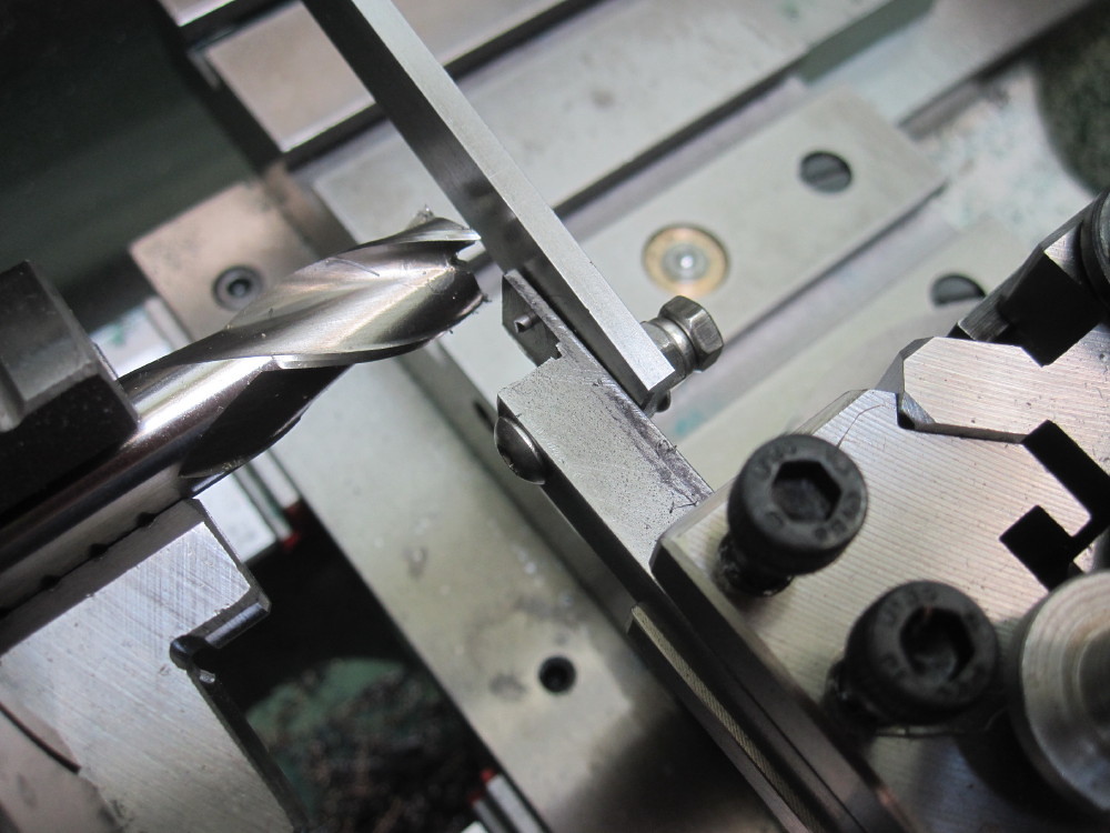 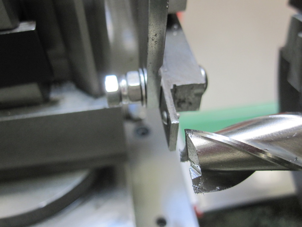 Trim the dummy 1/64" Rivets to 1.60mm length then Loctite into the beams. Trim the dummy 1/64" Rivets to 1.60mm length then Loctite into the beams.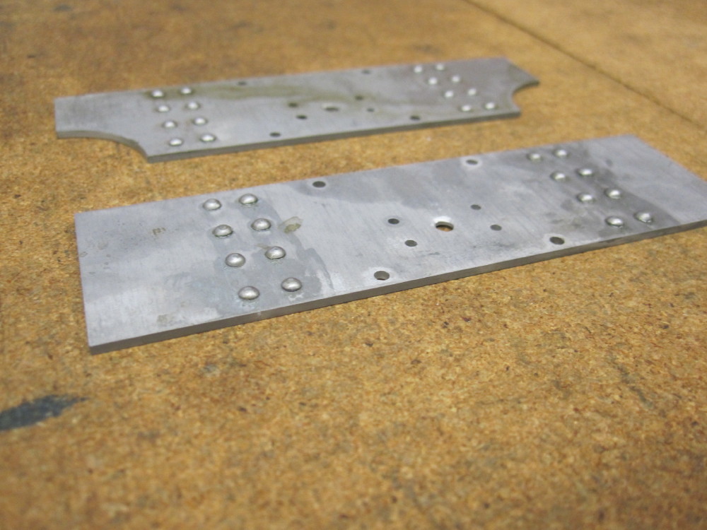 I consider this my Mark 1 prototype tool. I am pondering making one with different length inserts for different size rivets, but later..............I have a valve gear layout to got to sort out.......... I consider this my Mark 1 prototype tool. I am pondering making one with different length inserts for different size rivets, but later..............I have a valve gear layout to got to sort out..........
|
|
|
|
Post by menachem on Jul 11, 2017 2:34:54 GMT
I see all your posted photos and I can't wait to see the complete result of your project.
|
|
barlowworks
Statesman
  Now finished my other projects, Britannia here I come
Posts: 878 
|
Post by barlowworks on Jul 11, 2017 6:34:17 GMT
Hi Dazza
I also have a John the pump rivet shortener and also a bolt shortener using the same principle but with tapped holes and collars. If you fit a spring to the retaining lever it should allow you to accommodate different sized collars. Also some kind of stop at the bottom for the retaining lever may be a good idea. I have not used my rivet shortener in anger yet but these mods seem to be good ideas in my mind. Many thanks for sharing a very interesting build and thanks to John the pump for a very useful device
Mike
|
|
|
|
Post by Oily Rag on Jul 11, 2017 21:56:26 GMT
Working through Don Ashton's book, along side my CAD drawings and using the Dockstrader simulator, on page 4. Slow going for me to follow the text and style, ensuring I comprehend correctly and recognise the path , listening to ABC JAzz radio turned down low. Not the time for Nick Cave and the Bad Seeds played loud. Nick Cave or the Cure or Iggy Pop is for when I clean house!
|
|
|
|
Post by Oily Rag on Jul 16, 2017 21:58:44 GMT
|
|
|
|
Post by Oily Rag on Jul 17, 2017 10:29:28 GMT
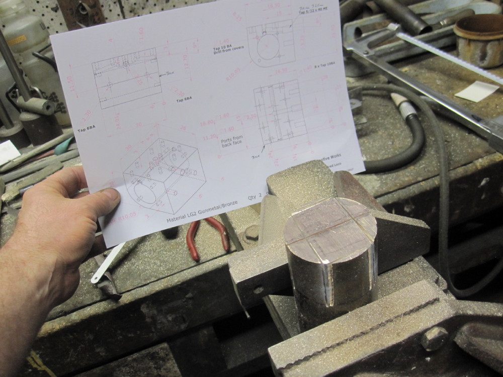
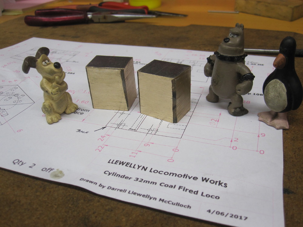
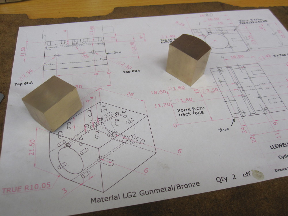
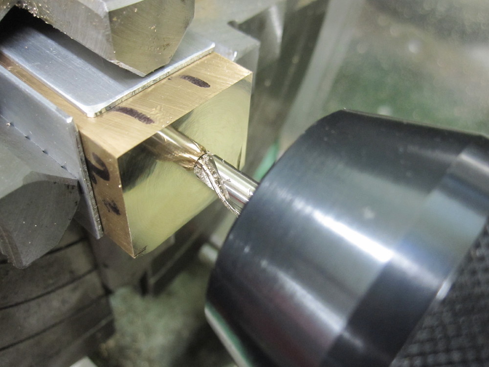
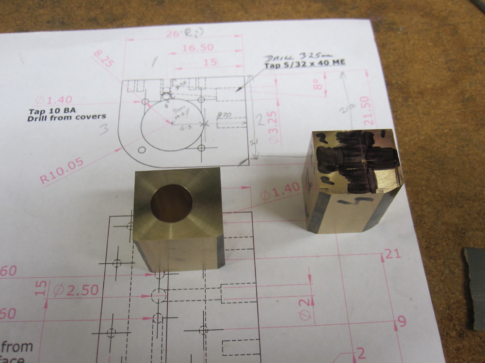
Nailed. Both cylinder block measure within .01mm bore to frame and valve surface. Got the second attempt at the Right block this time and a nice fish green curry stir fry for din dins. YAY! Off to print off the steam chest drawings. The front and sides of the cylinder and chest will be finish machined bolted together. I did this many years ago on my 5" loco.
|
|
|
|
Post by Oily Rag on Jul 22, 2017 21:42:20 GMT
As per Rodger's directions
Just for Kicks and Giggles, I learnt how to drill 0.50mm holes yesterday.
Solid Carbide PCB drill, 1/8" #3MT collet, top speed (not really fast enough actmco)
Makes dust, slowly slowly slowly , .5mm clean out and back in. DRO very useful on the quill.
My garden steamer now has oil holes in the connecting rods. Of what use are they, probably not much but...................................
All good knowledge and skill acquisition for the Gold Medal Winner I want to make in the years to come. My 1920 C17 #253 in 5". 
I also did some machining of the steam chests.
The Aprica ME 40 tpi taps are better than Sorba stuff! I have some sample of supposedly good HSS ones from the Tap and Die co on their way to down under. Sutton taps, very nice, the best, but special order for the ME40TPI breed and $70 each...............
The cheap ones are bowed and not much use in accurate tap holding set ups I have! The Model Engineering hand book has mistakes in the taping sizes, I just found yet another one, 3/16 x 40 as 4.30mm, the chart I have has 3.90mm and most other charts have it as 4.00mm . After some tests, I reckon 4.00mm is the correct size.
Test run 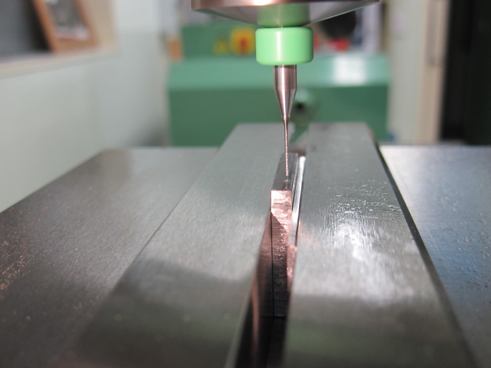
5.80mm deep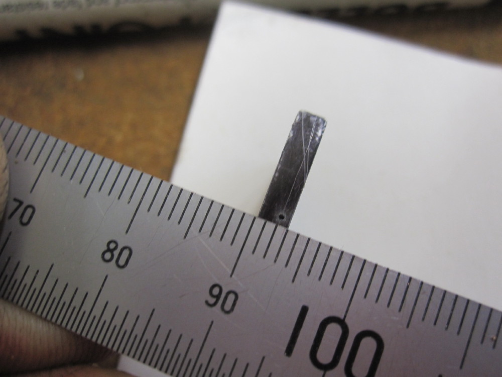 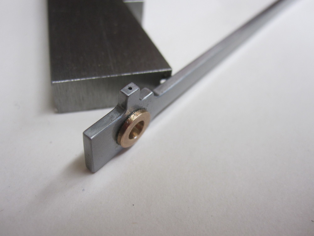
|
|
|
|
Post by Roger on Jul 22, 2017 22:07:10 GMT
Excellent work, I'm pleased that worked out for you. What's interesting is that this would have worked even if the bush was hardened, the carbide drills will drill ball bearings if you want.
As an aside, the little plastic collars they fit to these PCB drills are set on a special machine to be a preset length from the drill tip. Older PCB drilling machines hold the tools on the outside of the plastic setting ring in a spring loaded gripper. They're picked up by a high speed spindle with an automatic toolchange arrangement. This allows the drills to be picked up in the knowledge that they will drill to the right depth. More modern machines measure the actual length with a laser measuring device that also checks it's the right diameter.
|
|
|
|
Post by Oily Rag on Jul 23, 2017 1:27:26 GMT
Excellent work, I'm pleased that worked out for you. What's interesting is that this would have worked even if the bush was hardened, the carbide drills will drill ball bearings if you want. As an aside, the little plastic collars they fit to these PCB drills are set on a special machine to be a preset length from the drill tip. Older PCB drilling machines hold the tools on the outside of the plastic setting ring in a spring loaded gripper. They're picked up by a high speed spindle with an automatic toolchange arrangement. This allows the drills to be picked up in the knowledge that they will drill to the right depth. More modern machines measure the actual length with a laser measuring device that also checks it's the right diameter.
I wondered about the plastic ring, it makes pulling it out of the collet easier. |
|
|
|
Post by Oily Rag on Jul 31, 2017 20:50:06 GMT
|
|
|
|
Post by menachem on Aug 1, 2017 0:31:02 GMT
Well, since you have knowledge and skill. I know you can achieve your dream. Your doing well in your project.
|
|
|
|
Post by Oily Rag on Aug 1, 2017 2:43:44 GMT
Well, since you have knowledge and skill. I know you can achieve your dream. Your doing well in your project.
When I see the lovely locos made, jet engines, IC mutli cylinder engines and so on, I am going to run out of time in this life. I am also involved with full size heritage railway stuff and at the struggling Rosewood Railway.
www.facebook.com/RosewoodRailway/
that alone is enough for one person to fill two life times.
Cheers Dazza |
|
|
|
Post by Oily Rag on Aug 1, 2017 3:07:26 GMT
Hi Darrell, I am very pleased that you want to get to grips with Walschaerts valve gear. I can see that your main motivation is the lack of certain dimensions on the drawings for 'Eric' and dimensions that are not missing but appear to be wrong. Before playing around with a computer simulator for valve gears, especially where there is a question mark over whether you have all the dimensions and info required, I think it is best to first go back to basics and go through everything stage by stage. In this respect I prefer to construct a proper fully dimensioned drawing of the side elevation and the plan. As you draw and dimension each section everything should fall into place if done in the right order starting first with the valve dimensions and the port dimensions. As your model is quite a small loco certain features may have to be different from say a 5"g loco. I can tell you what full gear cut off and lap and lead I like in 3.5"g and 5"g for a 2 cylinder loco. I do not know whether more full gear cut off should be provided in a very small model and also whether less lap and lead should be provided. However let us assume a full gear cut off of 80%. Let us assume lap = 3/4 steam port width. Let us assume for your small model nil lead. You now have all the information that can easily be used to calculate the valve dimensions, and calculate the required travel. The travel is split into 2 components in Walschaerts. The lap component is provided by the combination lever proportions and is easy to calculate. The remaining travel component is provided by the return crank and expansion link etc. You do not want the expansion link to swing more than 25% either side of vertical in an 'all square' layout. With dividers compasses etc the required movement of the die block in the expansion link can be found. Then you sort out the 'back set' and construct the length of the return crank to provide this movement for full gear. As you go through this process it will be clear where the errors and missing dimensions are on your drawings. You have the advantage of not being restricted in the position of the motion plate due to the loco being outside framed. The swing of the lifting links affects die block slip and ought to be altered to give equal slip. This was a problem immediately apparent on your CAD drawing. I don't know whether the above is of help. If you have Don Ashton's book on Walschaerts gear then Don goes into much further detail, and also all the calculations are set out, and all the refinements that can be incorporated. You should not allow the die block to extend the full length of the expansion link slot to allow for die block slip. It has always been my understanding that wear in the valve gear increases valve travel. Cheers, Julian Julian, I am still going over the valve gear layout. I am convinced the published design has room for a lot of improvement. I have heard of others managing to get reasonable forward running but lousy reverse running. This backs up my attempts using the Dockstrader simulator. I am going over Don Ashton's book however the processes are not laid out in an easy to follow path to the objectives (what ever the objectives are) and then understanding the variables and the non variables is not an easy path for my mind. Martin Evans book has even less and the drawings are very basic and not always accurate. I am going to give it a go redrawing the current design and if it fails to work correctly, I just remake parts. I have one book that think is the best technical publication I have ever had the pleasure of using and learning from. "Inside Solid Works" by David Murray. From zero knowledge and understanding to a high level. Very well written. As MAM (lovely wife) is a "Technical Writer" in her day job (potter, artist, orchids, gardener,farmer and terrific cook after hours)so I have learnt to appreciate good writing. One evening I asked MAM to look at the DA book with me to seek the path. Her comment was she suspects the book is self published and a tech editor was not involved. It appears it was cut and paste from previous material into the book. That is not a criticism but an observation. I am glad some one gives it a go as it is never going to be huge income stream for Don. Bravo for putting it out there. I also find equations incomprehensible with my meager intellect. CAD for me. Cheers Dazza |
|
|
|
Post by Oily Rag on Aug 5, 2017 22:07:53 GMT
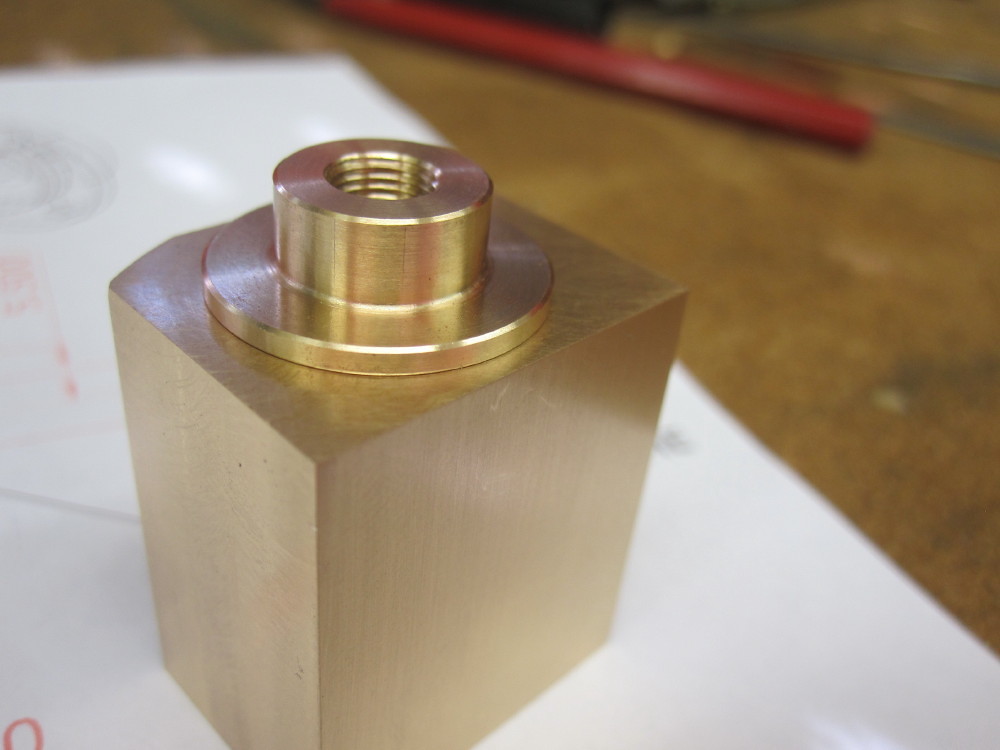
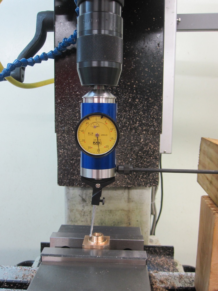
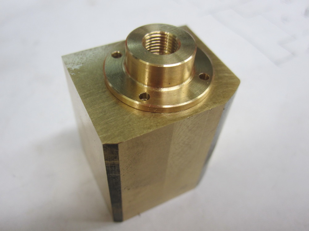
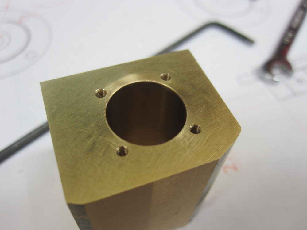
Supply top up in the Red Room.  The front cylinder covers are 2.50mm thick and the thinner outer section is 1.50mm so I made a "holdy thingy". (Dazza Technical term) 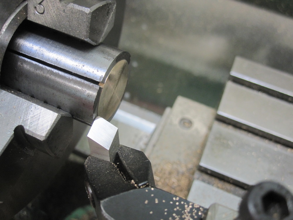 The treppaning tool I used on the wheels is into action again, hence the top rake for steel. 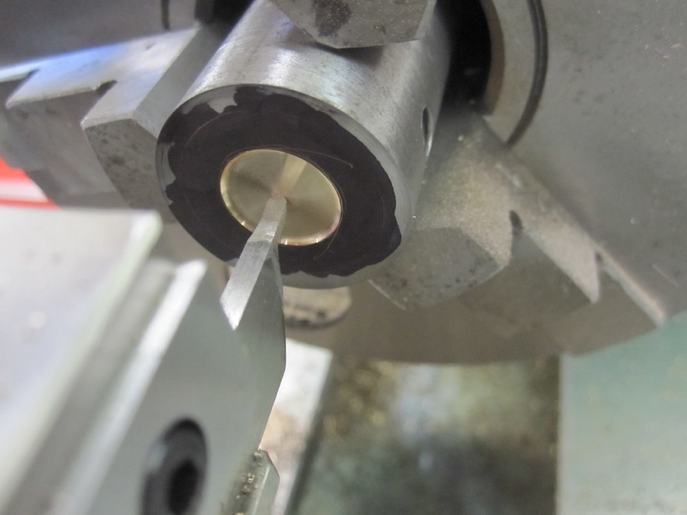 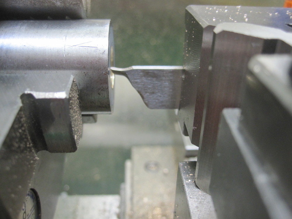 Worked a treat. The black is permanent marker for tool location. If I am careful I can get to .005mm . Machined the slid bar flat in situ and taped 10BA 2.20mm deep. 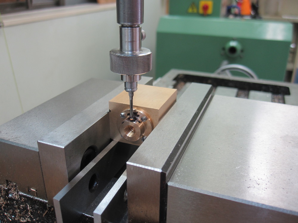 Rear covers done. 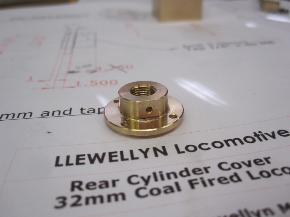 Front covers will be drilled in situ after the cylinder and chest are brought down to final length of 30.00mm , I will do that with them bolted together. 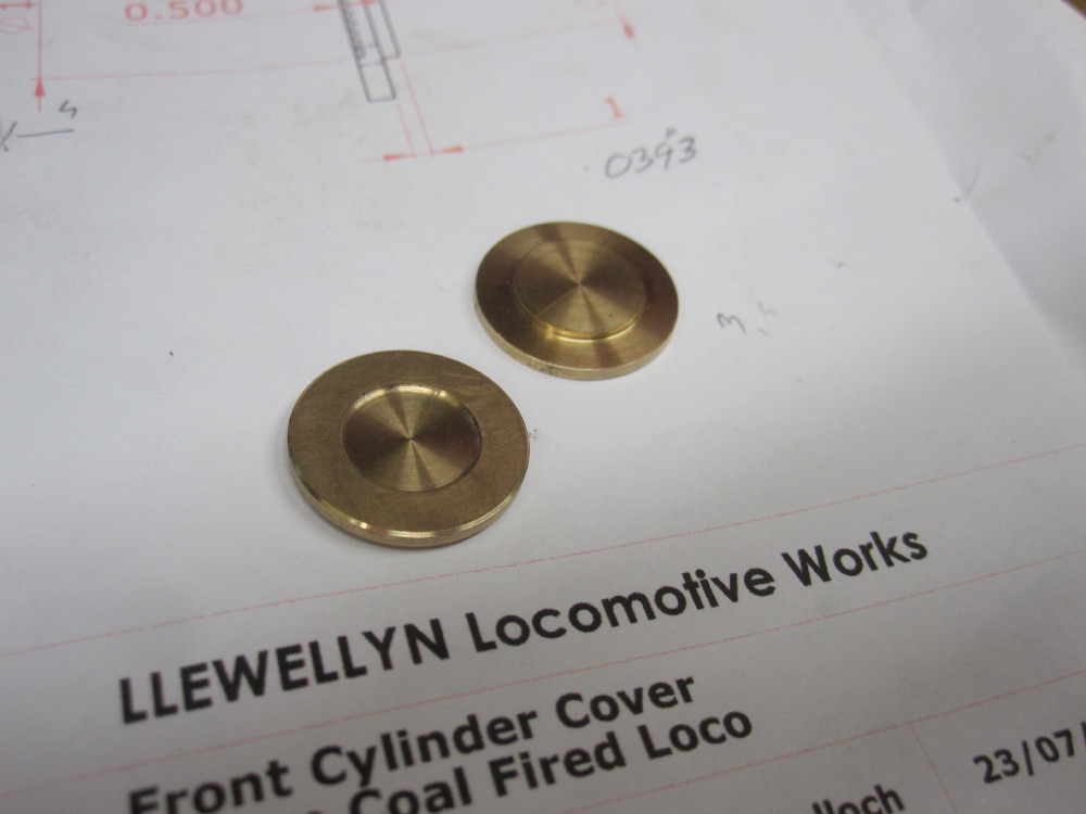 Due to pole work on Thursday there was no power in my street thus I could not work so I went off to the Ipswich Heritage Railway Heritage workshops. 1089 was in steam and soon off to Mayne for a weekend ARHSQD charter. 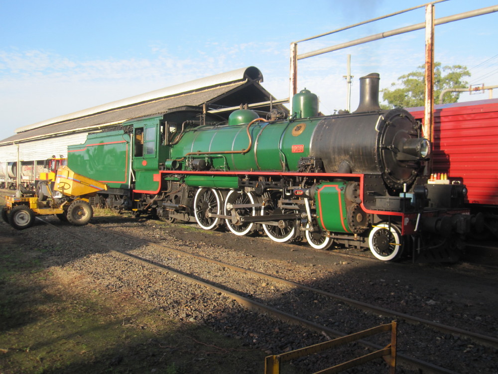 Dave and I cleaned the lathes, I gave the Colchester Master 2500 some heavy cleaning and oil! Much needed oil!!!!!!!!!!!!! The DD17 Tank loco #1051 is being rebuilt with a new all welded steel boiler. 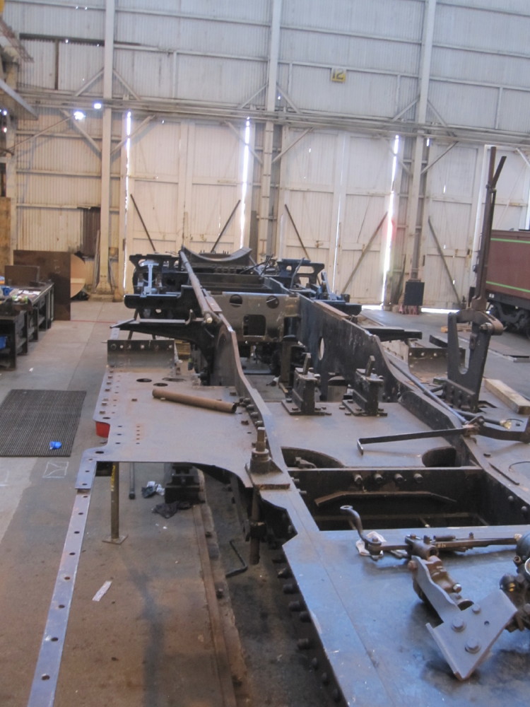 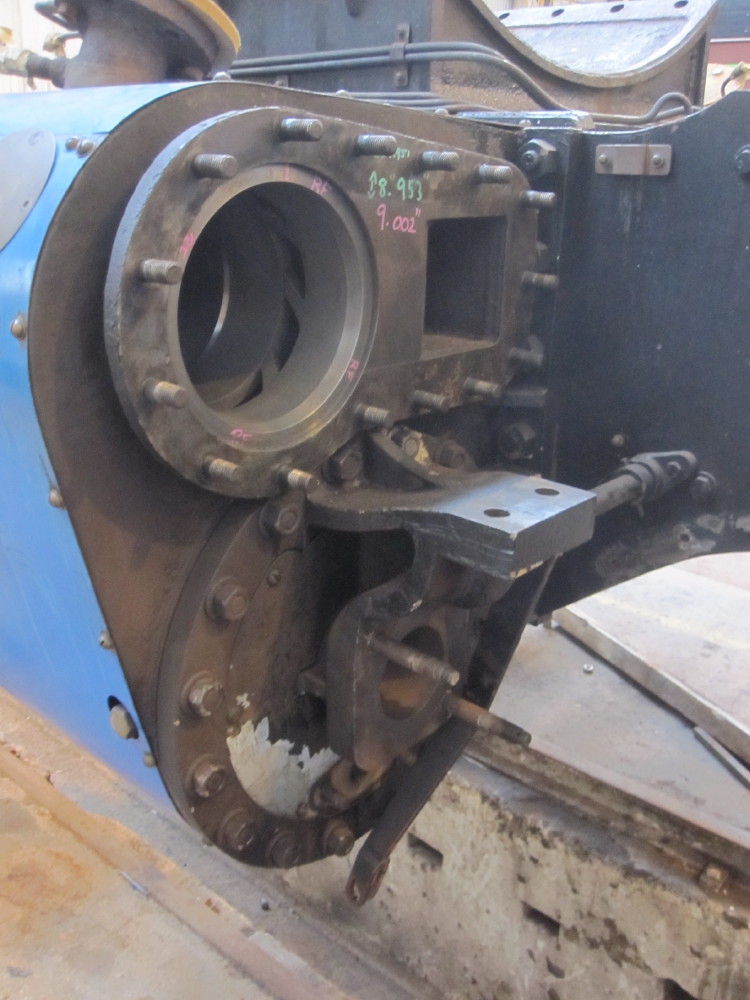 The Rosewood Railways RM64 "The Bug" is at the carpenters shop platform awaiting attention. The was the Commissioners inspection vehicle, even has an ice box for tall bottles of beer :-) It was built at the workshops circa 1930. 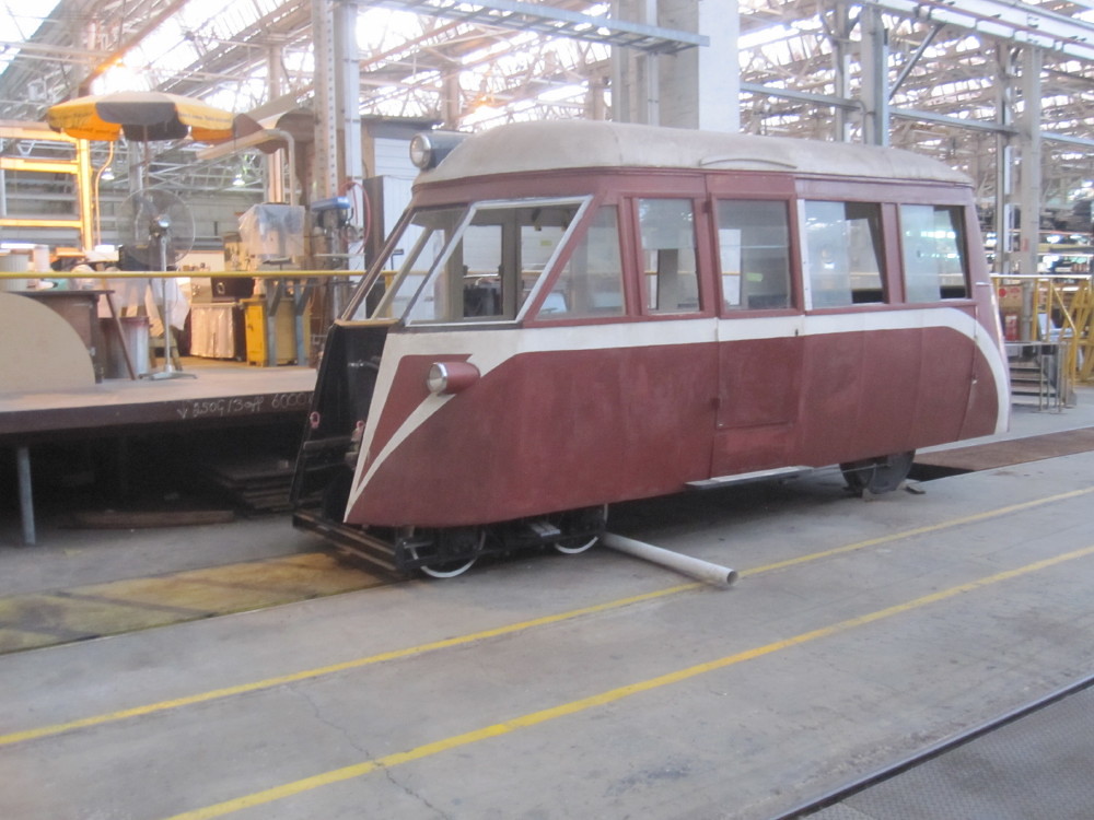 |
|
|
|
Post by Roger on Aug 6, 2017 5:59:23 GMT
I really like the "holdy thingy", little bits of tooling like this make jobs so easy.
|
|
|
|
Post by Oily Rag on Aug 6, 2017 21:20:37 GMT
I really like the "holdy thingy", little bits of tooling like this make jobs so easy. |
|


