|
|
Post by Oily Rag on Jun 17, 2017 21:11:50 GMT
As an aside I was taught it was bad practice to put a pin through the center of a shaft as it weakened the shaft. We were taught to put the pin to one side much like a cotter on a bicycle crank.
The major problem that may occur when drilling a 1.25MM drill through 10mm of black mild and kissing the corner of a silver steel axle is the drill defecting off the tougher silver steel and making a real mess of the hole/pin fit and the part. The stresses on a 5mm diameter axle of a 32 mm gauge garden steamer are very small, (factor in cube law)I am thinking that a press fit, loctite and cross pin will ensure the crank does not move on the axle. The wheel is just a snug press fit and 3mm grub screw to allow for gauge changes. (45-32mm)
|
|
|
|
Post by Oily Rag on Jun 17, 2017 21:26:46 GMT
From my slow education, the use of retaining products is not just " this is how and only this way applies" there many factors such as the surface finish (effects the amount retained), the clearances, the product uses, etc etc. Hence why the directions are rather generic. I am not an expert, however I used #638. To place a drop on the surfaces could do no harm. I am sure the Loctite is working well on the pins as the fit would allow one or two.01mm to be retained. If one was to use a product in a critical situation you would do a test run. Machine some test parts with the material and clearances, finish etc. Clean and apply etc. Let cure and test the resultant bond. The test might be as complicated as giving it a few good whacks with the hammer or gripping it and giving it a bit of heave ho to see who is boss. I will let you all know when I am sitting in my chair with nice glass of red and some smelly cheese watching the little steamer part company with a crank! Whoops! Oh well, pour me another glass will you :-)
|
|
|
|
Post by Oily Rag on Jun 19, 2017 21:41:01 GMT
I gave the 1/4 jig a whirl last night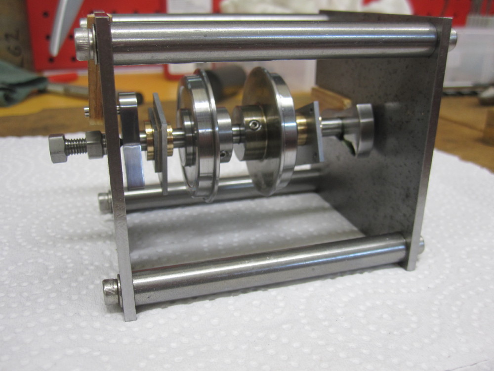 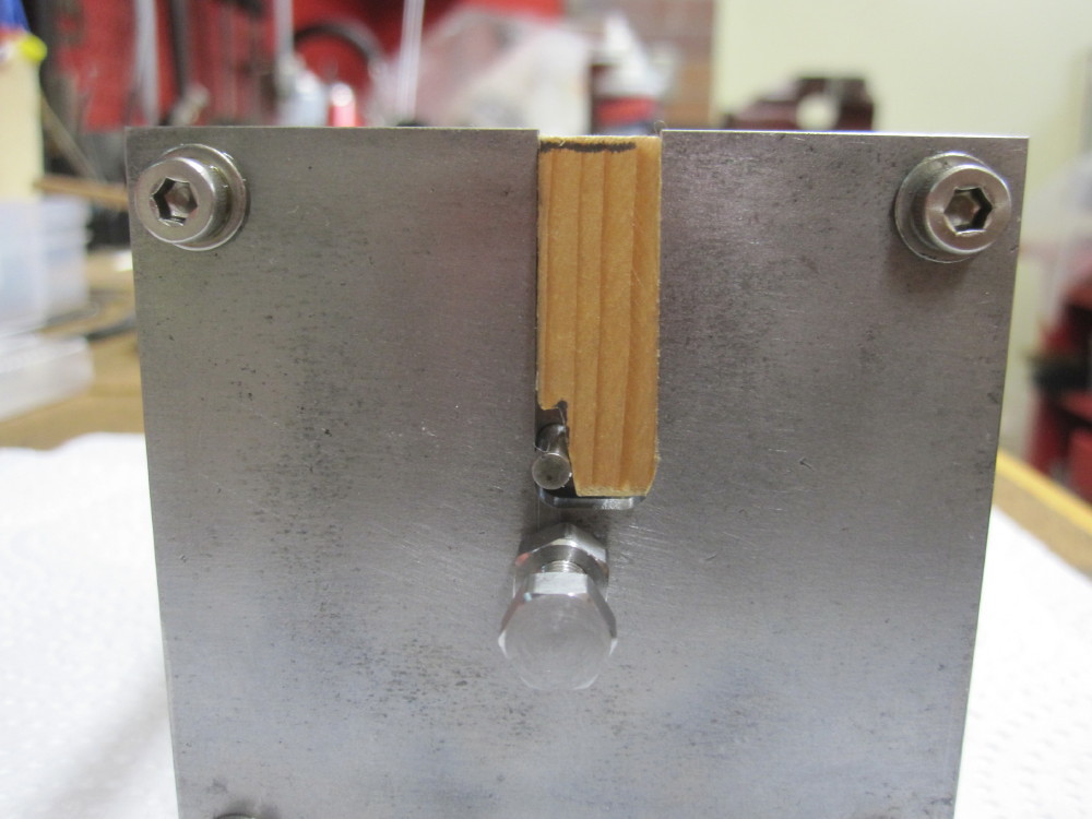  The fit of the left hand cranks was made looser, for the retaining goo to have a home, I centre popped the axle four times at 90 degrees to give it a light fit, to allow for the movement to snug the pins against the jig, note the wood wedges to ensure it stays there while the goo cures. Cure goo, go cure. There will be no Red Room action tonight, the Rosewood Railway Management Committee meeting upstairs in the house tonight. The fit of the left hand cranks was made looser, for the retaining goo to have a home, I centre popped the axle four times at 90 degrees to give it a light fit, to allow for the movement to snug the pins against the jig, note the wood wedges to ensure it stays there while the goo cures. Cure goo, go cure. There will be no Red Room action tonight, the Rosewood Railway Management Committee meeting upstairs in the house tonight.
|
|
|
|
Post by Oily Rag on Jun 22, 2017 21:17:42 GMT
|
|
|
|
Post by Oily Rag on Jun 26, 2017 19:55:52 GMT
|
|
|
|
Post by Roger on Jun 26, 2017 20:22:15 GMT
Excellent work as always. My best tips on drilling small holes with Carbide PCB drills are to do it dry and always with the handwheel for infeed. You won't feel anything with these drills, and sudden movements are what cause breakages. If you use the depth DRO (if you have one), go in very slowly with a fairly high spindle speed and watch the dust come out of the hole. You won't need to centre drill the hole, the drill is stiff enough to not need it. Just start extra gently as you touch down.
I'm making the drills sound more fragile than they are, they're pretty strong, but breaking one when it's overloaded makes it hard to get the broken part out. Drilling it to dust means that any broken bits can easily be removed without drama because they're not embedded deeply into the material.
Using these techniques you can drill just about anything, even hardened tool steel, and down to 0.2mm if you like. It's not difficult if you take it gently.
|
|
|
|
Post by Oily Rag on Jun 27, 2017 2:49:54 GMT
Excellent work as always. My best tips on drilling small holes with Carbide PCB drills are to do it dry and always with the handwheel for infeed. You won't feel anything with these drills, and sudden movements are what cause breakages. If you use the depth DRO (if you have one), go in very slowly with a fairly high spindle speed and watch the dust come out of the hole. You won't need to centre drill the hole, the drill is stiff enough to not need it. Just start extra gently as you touch down. I'm making the drills sound more fragile than they are, they're pretty strong, but breaking one when it's overloaded makes it hard to get the broken part out. Drilling it to dust means that any broken bits can easily be removed without drama because they're not embedded deeply into the material. Using these techniques you can drill just about anything, even hardened tool steel, and down to 0.2mm if you like. It's not difficult if you take it gently. Rodger, I have a fitted a depth DRO to the quill, (well worth the $65.00 and effort to fit!) I will be gentle. The fastest I can spin up the mill is 2,500 rpm. I am hoping that is fast enough?I have 3-4mm of mild black and then 1mm of the bronze bush. I was wondering about being very slow on the break through in the bush hole as it could snatch. Do you peck drill? But I assume it is OK to drill slowly in , with just one past, watching the dust come out as you say, as they look to be a different geometry to a normal fluted twist drill. I have a good German ROHM keyless chuck, it does have 0.05 -0.10mm run out. I do not have a collet set up for the 3MT Mill drill quill, I am concerned it might be too much wobble on the 0.50mm drill  How do you hold your little drills ? How do you hold your little drills ? Thanks for your advice and inspiration, your Speedy thread is a host of marvelous info and I cannot absorb it all, quick enough. Cheers Dazza |
|
|
|
Post by Roger on Jun 27, 2017 7:59:27 GMT
Hi Dazza,
That's good, I fitted one too. That will be handy for judging how fast you're progressing, and also for finding the bottom of the hole when you withdraw every 0.5mm say. I wouldn't go any deeper with each cut, just to be on the safe side. The good thing about this method is that you don't get stringy swarf, only dust. That's why I don't use lube, it makes it easier for the dust to find its way out.
2500RPM is fine, it just means it takes a little longer and is more susceptible to jerky infeeds. I don't suppose I use much more than that anyway, I don't like the mill running at crazy speeds, it doesn't do the bearings any good.
Breaking through won't be a problem if you're doing it the way I suggest. You'll know from the DRO when that's about to happen so you can be extra careful.
I generally use an 1/8" ER32 collet for the small drills because it has less runout than the drill chuck. You may find that your keyless chuck sometimes picks up with less runout than that, so it's worth experimenting. It does sound like a lot though. Is it because the whole chuck is out of true on the mandrel? Maybe you can do something about that? Maybe it's worth investing in an 1/8" collet, especially if you get a liking for this sort of drill. They all have 1/8" shanks for any diameter, so you only need the one size.
|
|
|
|
Post by Oily Rag on Jun 27, 2017 22:45:24 GMT
Hi Dazza, That's good, I fitted one too. That will be handy for judging how fast you're progressing, and also for finding the bottom of the hole when you withdraw every 0.5mm say. I wouldn't go any deeper with each cut, just to be on the safe side. The good thing about this method is that you don't get stringy swarf, only dust. That's why I don't use lube, it makes it easier for the dust to find its way out. 2500RPM is fine, it just means it takes a little longer and is more susceptible to jerky infeeds. I don't suppose I use much more than that anyway, I don't like the mill running at crazy speeds, it doesn't do the bearings any good. Breaking through won't be a problem if you're doing it the way I suggest. You'll know from the DRO when that's about to happen so you can be extra careful. I generally use an 1/8" ER32 collet for the small drills because it has less runout than the drill chuck. You may find that your keyless chuck sometimes picks up with less runout than that, so it's worth experimenting. It does sound like a lot though. Is it because the whole chuck is out of true on the mandrel? Maybe you can do something about that? Maybe it's worth investing in an 1/8" collet, especially if you get a liking for this sort of drill. They all have 1/8" shanks for any diameter, so you only need the one size. Just checked again, .06mm total runout on 1/8" diameter in the chuck. Used a piece of raw 1/8" Seco HSS. So I just ordered 1/8" 3MT collet via ebay. Thanks for your reply and advice, very much appreciated. Cheers |
|
|
|
Post by Oily Rag on Jun 28, 2017 21:07:49 GMT
I rounded the edge of the 3/8" slot cutter, they last longer (corner stays put longer) and this gives the corner a profile I was after and did the oil box on the rods. I reduced the 3mm width to 2.4mm as it looks better to my eyes.  How do I hold the rod flat for polishing as it is delicate? A quick ponder. Double sided tape on a bit 3/8” tool steel. Worked a treat, down to 1500 grit. How do I hold the rod flat for polishing as it is delicate? A quick ponder. Double sided tape on a bit 3/8” tool steel. Worked a treat, down to 1500 grit.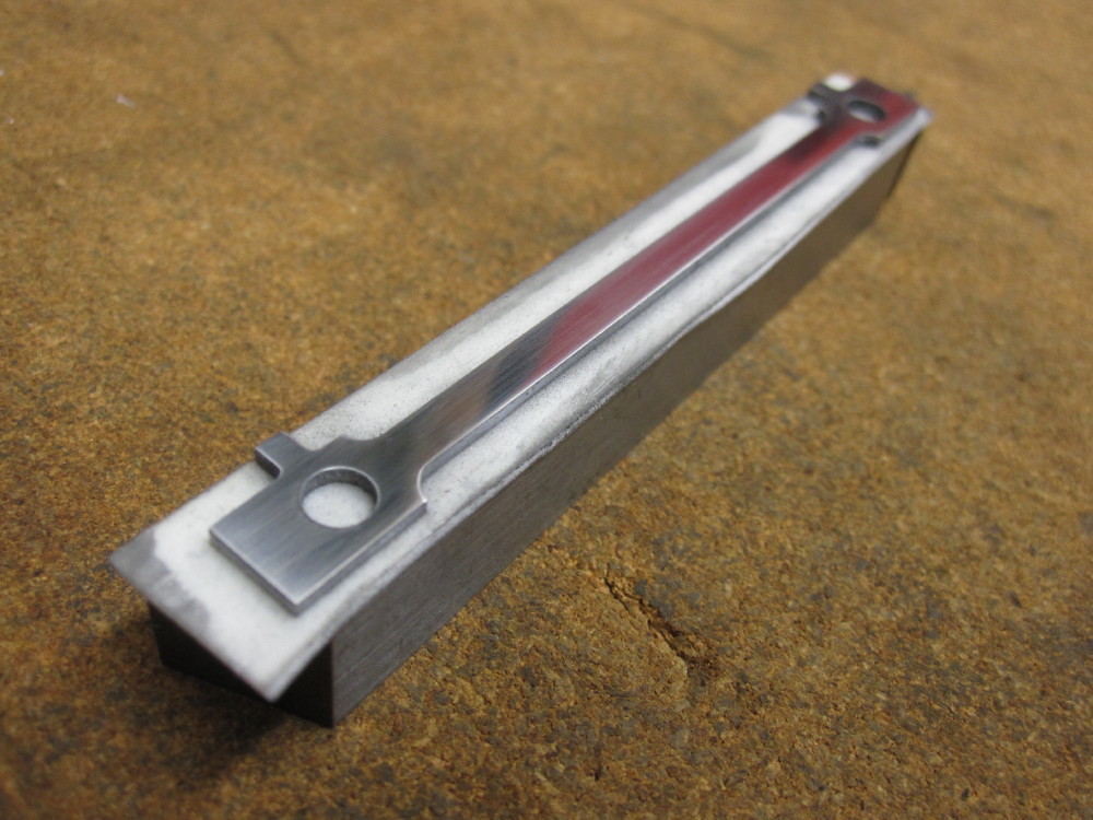
I will dress the edges first and then the sides, but another day as I went upstairs to watch "Mad as Hell" for a laugh.
|
|
|
|
Post by Oily Rag on Jul 2, 2017 20:30:39 GMT
Inspiration came from page 388 Model Engineer Vol 187 No 4157
Took me all of Sunday morning to make and over an hour and a half to grind the tool in a piece of Sutton 1/4" HSS. I am terribly slow but if I watch the clock it is no longer is a hobby, it becomes work production and the enjoyment evaporates.
I got all oily with, with, with excitement when it worked a treat.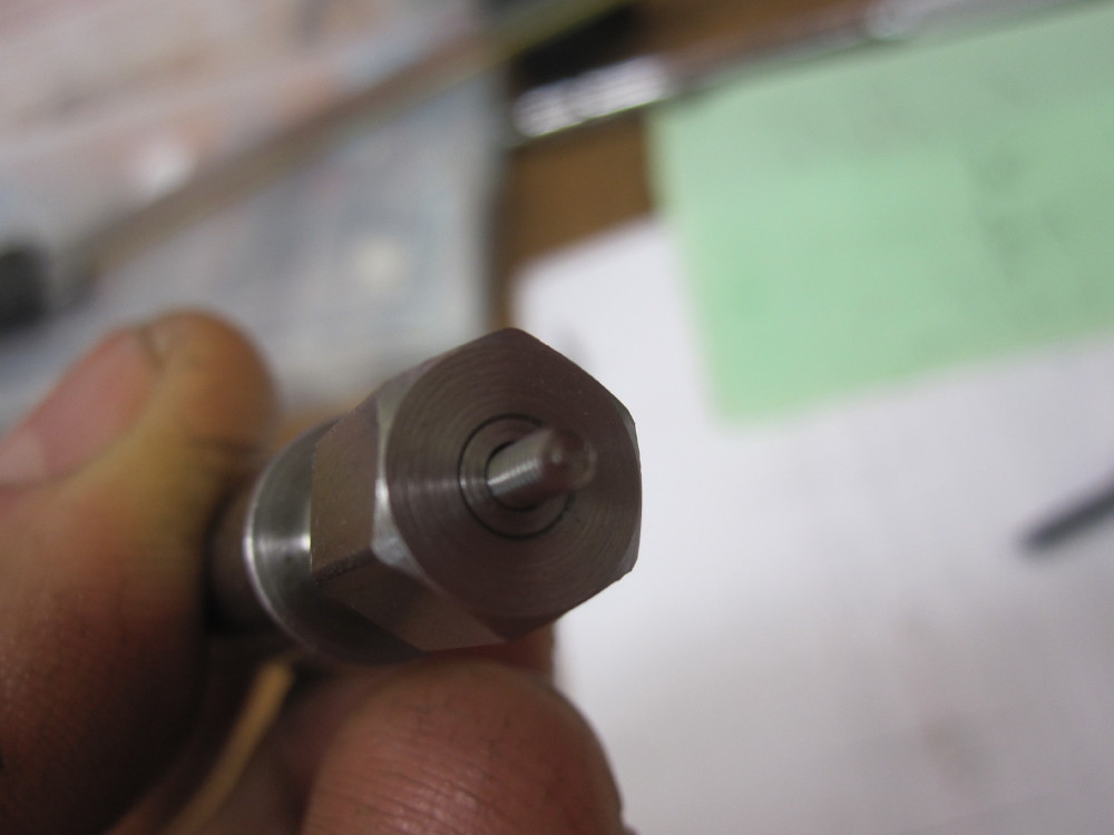 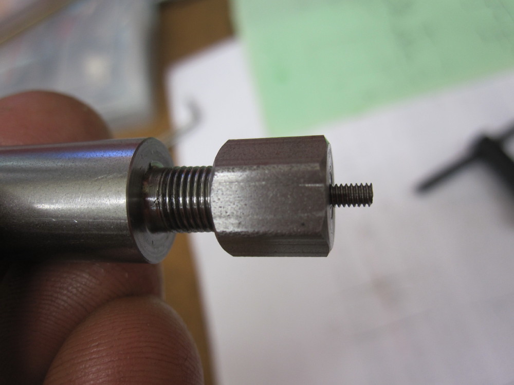 8 BA Part to length and a slight profile radius on the end and a clean thread start. 8 BA Part to length and a slight profile radius on the end and a clean thread start. 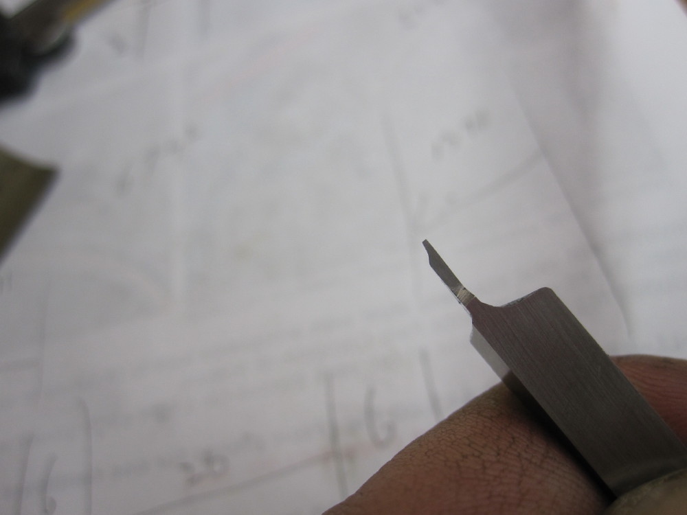 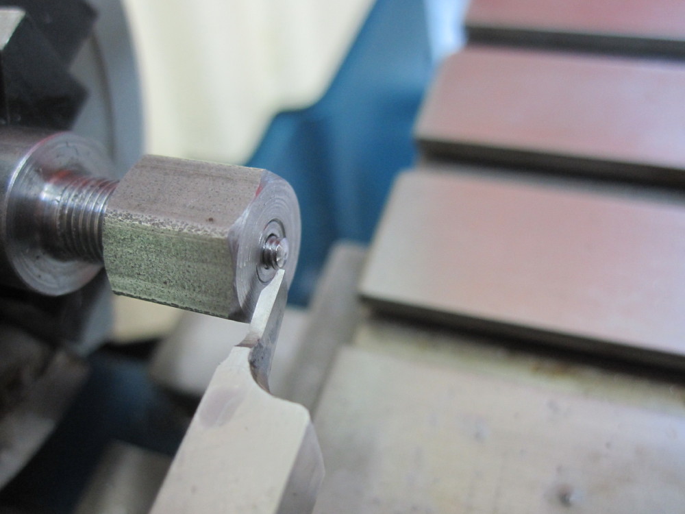  I made it so I can make different collets for different BA or metric sizes. Will be used set up in the Cowells.More excitement when the chassis was rolled, smooth as silk I made it so I can make different collets for different BA or metric sizes. Will be used set up in the Cowells.More excitement when the chassis was rolled, smooth as silk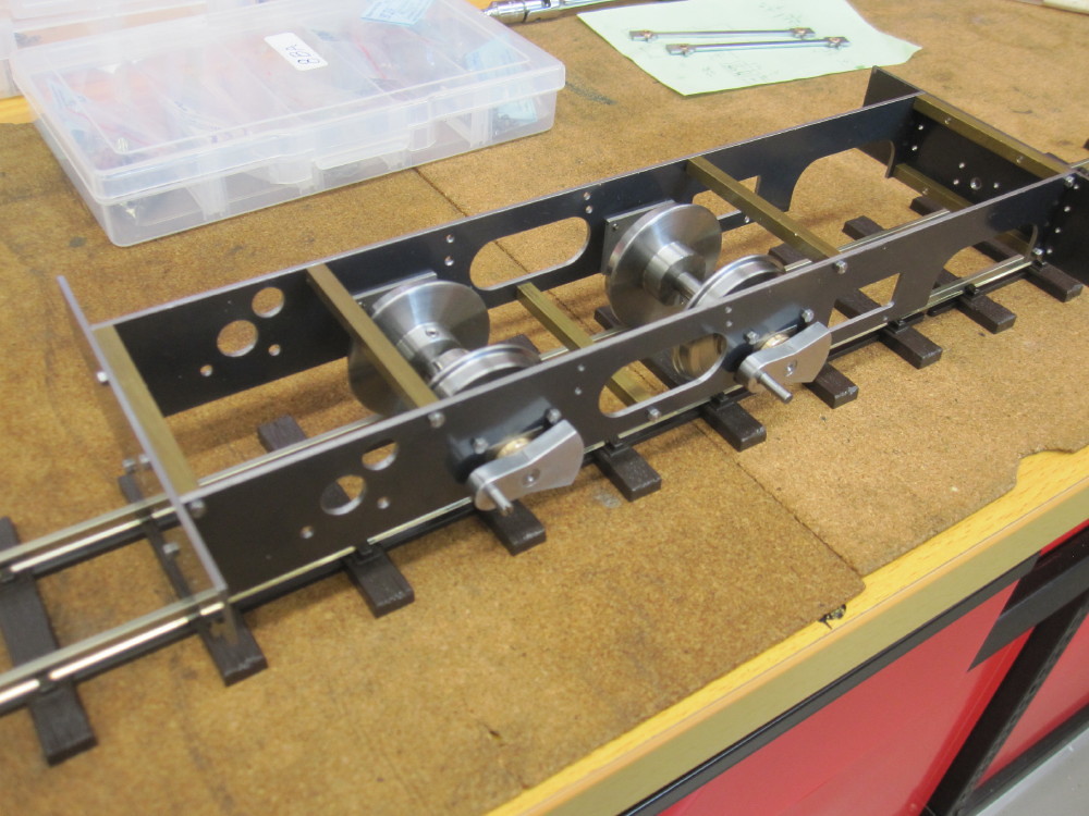 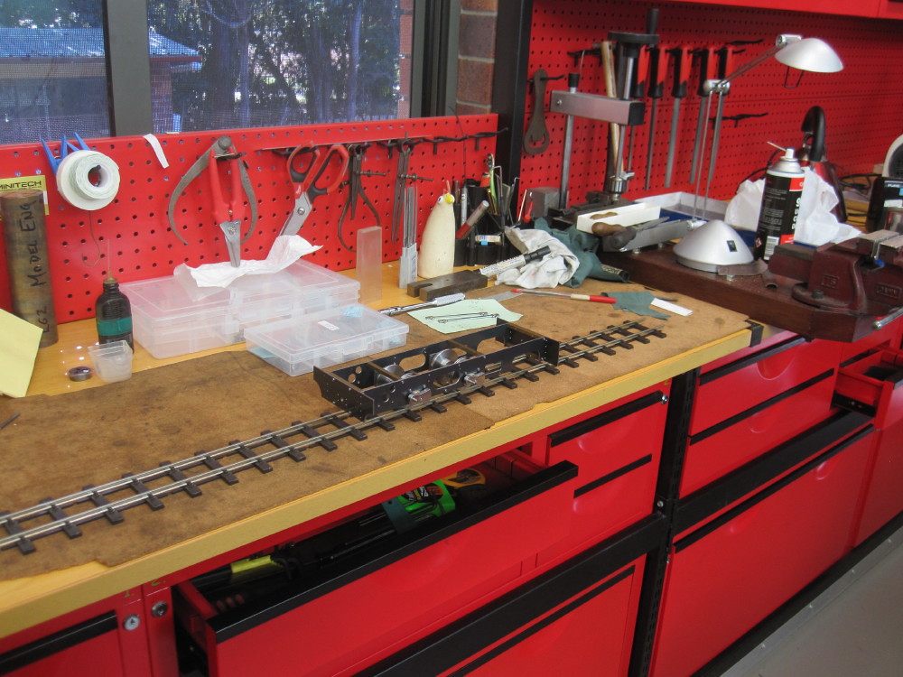
|
|
|
|
Post by springcrocus on Jul 2, 2017 21:38:33 GMT
Which Cowells machine do you have, Darrell? A quick recap of your thread failed to enlighten me, but that could easily be down to my own stupidity.
Regards, Steve
|
|
|
|
Post by Oily Rag on Jul 2, 2017 22:39:03 GMT
Which Cowells machine do you have, Darrell? A quick recap of your thread failed to enlighten me, but that could easily be down to my own stupidity. Regards, Steve The 90ME one 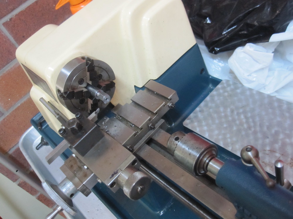 I got it shipped out from the UK a few years ago, it was brand new, never used, test certificate was dated June 25th 1985. An indulgence, for 1/3 the price I could have got an Asian lathe. In hindsight I think it should have, for various reasons. |
|
|
|
Post by jordanleeds on Jul 3, 2017 6:20:47 GMT
Wonderful work! I'm sure we met in llangollen a.couple of years ago when you came for a look round the shed and the patriot ?
|
|
|
|
Post by Oily Rag on Jul 3, 2017 20:53:32 GMT
Wonderful work! I'm sure we met in llangollen a.couple of years ago when you came for a look round the shed and the patriot ?
Sadly we drove through Llangollen this year as we visited the Welshpool and Llanfair (for the first time) and the Pontcysyllte Aqueduct. I hope to get to Wales again next year as we might be exhibiting at the Bespoked hand built bike show in April. |
|
|
|
Post by Oily Rag on Jul 7, 2017 22:17:59 GMT
My Version of Eric and its Valve Gear, my dim mind needs help with design and understanding.
“If this presents a hopeless minefield, as it seems to have done inexcusably even in many drawing offices” Don AshtonDon, include my humble drawing office. The time has come to learn more about Walschaerts valve gear and I have need of help for my dim intellect to comprehend my mystery. The time has come to learn more about Walschaerts valve gear and I have need of help for my dim intellect to comprehend my mystery.
My reading via various books from Don Ashton, Don Young to Martin Evans and looking at many steam loco model designs that are surprisingly vague about valve gear dimensions or omit some details has me in a spin. I read vague mentions of fiddle to perfect valve events, or equal port cracking open and so on and so on, till my brain hurts. Sigh! I have no understanding of what compromises the valve gear must or can have.
Brian Wilson’s Steam Trains in the Garden (2015 Print) is the stimulation for my garden gauge loco build and I am very much enjoying making my 0 4 2 coal fired version of Eric and the time approaches for the motion construction.
The book with its drawings does not have a fully dimensioned valve gear layout of axis and centres, which surprises me. There are various parts with some dimensions but there are many missing location dimensions for the expansion link trunnion pins and a few other items. Page 37 has a drawing "Walschaerts Valve Gear Assembly" with three dimensions, one is for the motion bracket mounting angles bolt centre holes from the front of the frame as 88mm but is must be incorrect, as measured off the 1-1 scale drawing it is approx 92mm. Also the mounting brackets hole position centres are not fully dimensioned in their drawings. All this effects the expansion link location. One can reverse engineer its location (Via 3D CAD drawings that I am doing) but there is uncertainty due to assumptions that have to be reached. So in the Docstrader simulator I get some thing that looks good in forward but impossible to get a proper mid gear and to even work in reverse, aghhhhh.............! The adjustable eccentric rod is fine, and it is practical to work off the actual finished job as the build errors may creep in, but in my mind one should have a theoretical set of dimensions to aim for, to cross check etc. (refer to attached Queensland Railways Class C17 drawing) 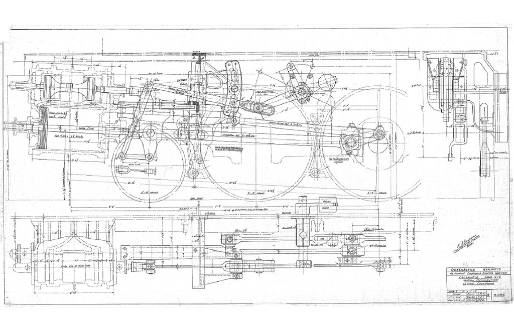 I blame my lack of intellect to digest this !1. I have loaded the Dockstrader outside admission valve gear simulator and spent hours going around in circles, using what should I deduct are the Eric dimensions. However I am finding it does not work very well. I blame my lack of intellect to digest this !1. I have loaded the Dockstrader outside admission valve gear simulator and spent hours going around in circles, using what should I deduct are the Eric dimensions. However I am finding it does not work very well.
2. So the can the collective wisdom cast their minds over this or give some assistance?
3. Due to a slight loss of motion due to running clearances even in new valve gears the valve travel will be slightly less than theoretical (as compared to the CAD program or simulators) so should one have a wee bit of extra travel to compensate? In the 16mm gauge loco it may be only 0.10 – 0.30mm. I know in full size that such slack was often allowed for at the workshops.
4. To my mind the Eric valve needs to be bigger to give a bit more lap, but? 
5. I cannot get the Docstrader input data to copy and paste so here are the pics of the input data. Some items I have not been able to understand, such as the "ReverseArm to CentNorm" and "ReverseArm to CentNorm MAX" 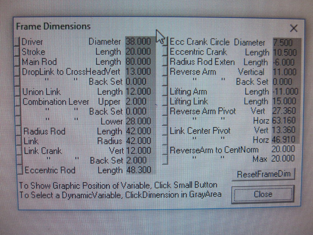 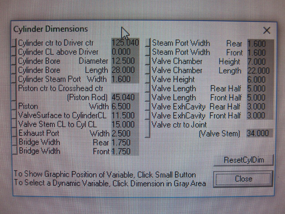
|
|
|
|
Post by Oily Rag on Jul 7, 2017 23:29:35 GMT
The Eccentric circle diameter given (7.5mm) and length (10.5mm) does not make it 90 degrees to the crank pin ??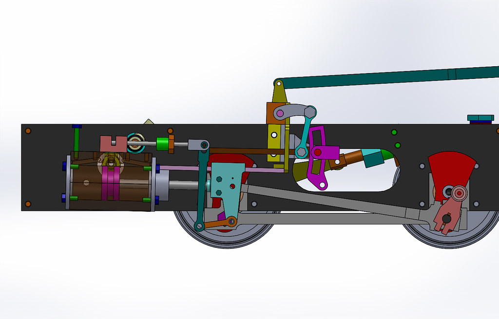 I modified the motion bracket to have a separate slide bar rather than folding it as part of the MB. I have not changed the geo of the V gear, but I do have to alter the lifting arm pivot a couple of mills to take it back to B. W's location, or where I think he wants it. I modified the motion bracket to have a separate slide bar rather than folding it as part of the MB. I have not changed the geo of the V gear, but I do have to alter the lifting arm pivot a couple of mills to take it back to B. W's location, or where I think he wants it.
Cheers
|
|
|
|
Post by Roger on Jul 8, 2017 6:21:23 GMT
Firstly I must say that I know very little about valve gear, but a few things I've found it might be worth mentioning. Don Ashton is the expert on these matters and you might like to contact him. He's not been well though, so don't expect instant answers.
The first thought is that Walschaerts valve gear is, in my opinion, a ghastly bodge, not the improvement over other gears I assumed it to be. It only achieved the level of acceptance because it's easy to maintain. The events won't be the same in forward and reverse, that's simply not possible.
Secondly, if you change one dimension, everything else is changed to some degree or other.
I'm not sure why your simulator requires so much information, the one Don Ashton showed me only needs the bare minimum. You can download that, but I'm not home at the moment to be able to tell you where from. You can see the output of it for my locomotive in the valve gear section of the wiki that I started if you Google "Building LBSCs SPEEDY". I've tried to explain the events as I understand them from the diagrams the simulator output.
Don Ashton reworked the SPEEDY valve gear and published a dimensioned line drawing for the critical dimensions. That was all that was needed to then flesh out the required parts.
Another thing I learned was that you need a long cut off to guarantee starting on a two cylinder locomotive, regardless of where it stops. If you had 50% cut off, that would leave the opposite cylinder on TDC, so you could get stuck. So although 60% cut off sounds like a lot, it isn't. Wear on valve gear will reduce the cut off over time, so a generous cut off to start with is helpful.
I don't know how to go about designing the valve gear, so I can't really help with that. I just wanted to point out that the idea of a "theoretical setup" is not an idealised one. It's all a compromise. I believe you can achieve acceptable valve events from a range of different geometries, but getting them to be in sensible proportions so they look right and work on your locomotive is something else. Excessive movement will occur with some of the arrangements, and those may not be practical. On mine, it's difficult to get the required clearance between the expansion link and other parts of the mechanism when it's notched back.
The geometry on mine ended up with it not being like the full sized locomotive, the crosshead has an extension to move the connection to the union link down considerably. For me, it's more important that it works well than it looks precisely to scale.
I'm sorry if this muddies the water even further!
|
|
|
|
Post by keith1500 on Jul 8, 2017 8:24:35 GMT
No,no walscherts valve gear is not a ghastly bodge. Consider the valve gear as a precision instrument. It combines two motions together to get the valve events. It is really rather cleaver and can be complex too. sad to hear Don is not so well. Wish him better. He quite rightly advocates the only walscherts is the correct one. I fiddled mine on my speedy to get the loco to behave and perform as best I can but I know in my heart it's not right and you can tell if you have driven other locos the benefits of well set up valve gear.
My advice is spent plenty of time on it. There are programmes out there in to which you add the various dimensions. You have some of these dimensions already. Finally work down to the last thou on this bit of your loco. A cad drawing programme is most handy.
|
|
|
|
Post by Oily Rag on Jul 9, 2017 8:35:39 GMT
No,no walscherts valve gear is not a ghastly bodge. Consider the valve gear as a precision instrument. It combines two motions together to get the valve events. It is really rather cleaver and can be complex too. sad to hear Don is not so well. Wish him better. He quite rightly advocates the only walscherts is the correct one. I fiddled mine on my speedy to get the loco to behave and perform as best I can but I know in my heart it's not right and you can tell if you have driven other locos the benefits of well set up valve gear. My advice is spent plenty of time on it. There are programmes out there in to which you add the various dimensions. You have some of these dimensions already. Finally work down to the last thou on this bit of your loco. A cad drawing programme is most handy. I have drawn it in CAD, 3D but that still does not determine what the model designer intended, if they knew understood what they intended. |
|