|
|
Post by Oily Rag on Aug 6, 2017 21:39:22 GMT
Sunday, I drill and tap the 6BA cylinder mounts and the exhaust steam passage while set up. Made some more bushes for 6 and 10 BA to fit # "PTLST" which I use in the Cowells. (# Part to length screw thingy) So sweet to part the screws to length and the thread starts are clean and no clean up required. Have I said I like DRO recently ? All the brass Hex cover screws are trimmed and the machine marks and pip on the hex heads are cleaned off with 100 grit and stored in the drawers under the erection shop. (Evection shop is a new Red Cabinet just for this loco and MAM's Round house loco.
I just had to mount the unfinished cylinders onto the frames so when MAM came home from her Pottery Glazing Course I had some thing to show.
I also spent some time in the back yard before dark , playing with Peco SM32 points and reconfirming the layout. Soon the track gang will be in action.
Oh and the name of the loco is going to be "Chauncey" . After my nephew. 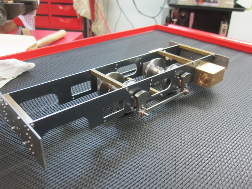 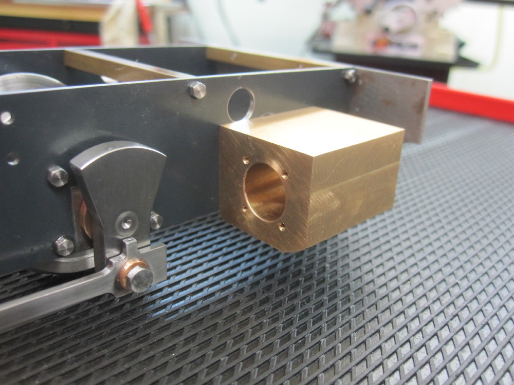 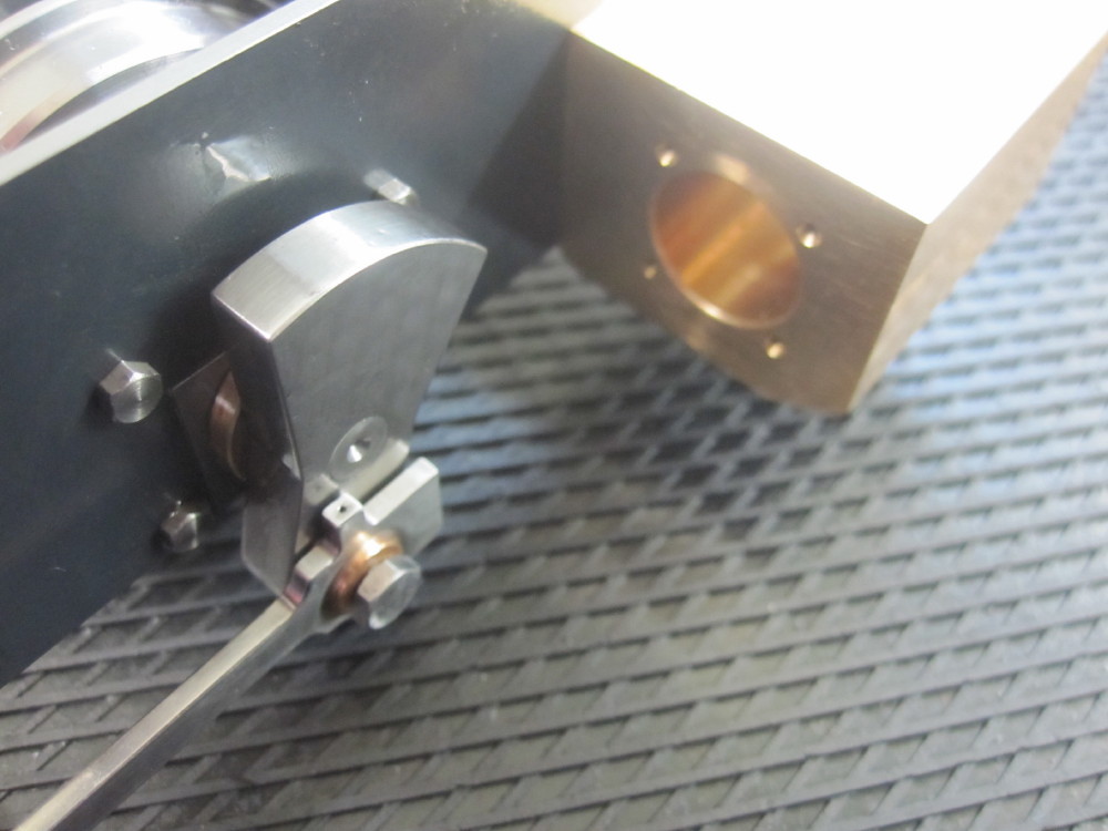
|
|
|
|
Post by Roger on Aug 6, 2017 22:20:10 GMT
I really like the "holdy thingy", little bits of tooling like this make jobs so easy. Excellent! Lateral thinking and fancy footwork to get out of trouble is what makes life interesting, especially when it all comes good in the end and you get the payoff. |
|
|
|
Post by Oily Rag on Aug 13, 2017 20:27:47 GMT
Made the piston rod gland nuts. Rather than a hex nut I made them for a 1.00 mm Tommy bar. Looks nicer and easier to use than a spanner.
I must admit, I made three, one was ruined when the drill chuck fell out! Running on the highest speed, rattly straight cut gears and 1.00mmm drill, my excuse is the vibration urged it to jump out. The first time this has happened to me. I make sure now that it is well tap tap tapped home. The taper is all good and clean. Perhaps there was not the thrust of the bigger drills to give it a constant nudge in.
I screw cut the gland nuts in the lathe. I know many do this and chase the thread with the die but my 40 TPI ME dies are not able to to work tight to a shoulder. I like the crank handle on the Myford, makes doing the short threads a treat. No need for power traverse.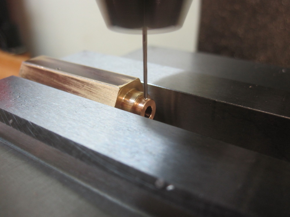 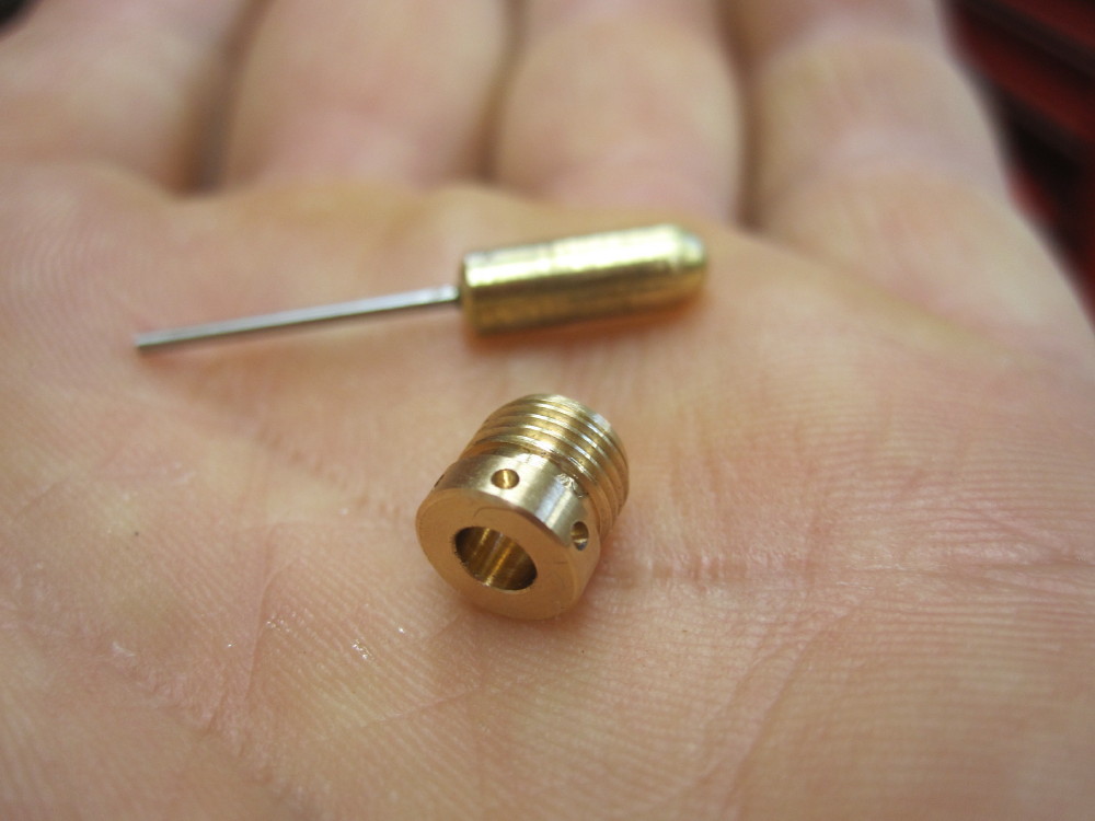 
|
|
|
|
Post by Oily Rag on Aug 16, 2017 23:00:52 GMT
Last night it was the valve rod gland nuts. 3/16" x 40 TPI ME screw cut in the 254. I am going to work down to screw cutting smaller sizes and also small internal threads in the days, years to come. 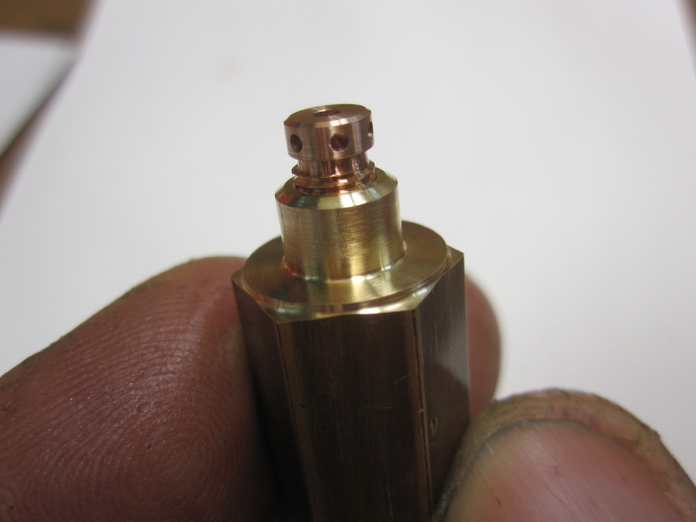 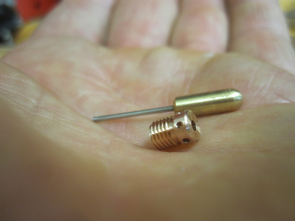
|
|
|
|
Post by Oily Rag on Aug 16, 2017 23:19:56 GMT
I have after much anguish, frustration and many hours of reading, learning and evening CAD time and using the Docstrader simulator I have redrawn the valve gear for Brian Wilson's Eric and now have valve events that appear to work well. It was a pleasing moment when suddenly it all appeared to fall into place. Where as before it was impossible to have work in reverse unless a lot of compromise was done to forward running events. As it is now, I am confident The real proof will be in making the loco and its steaming/running qualities.
|
|
|
|
Post by Oily Rag on Aug 18, 2017 2:24:59 GMT
Thursday afternoon had me wanting to walk into the desert and die an agonising death
Why is this so ?
I chipped the paint on a new Llewellyn frame I was assembling with Campy Record. So the Punter has to wait longer.
After dinner to make penance or a version of self flagellation I went into the Red Room and spent nearly 5 hours cleaning machines, sweeping floors and crannies and moped the floor, then oiled the machines. It was after 11pm to bed. Then up at 5 am to drive across Brisbane to drop the frame to the painter. Sigh! 5 steps forward and one step backwards. So tonight and tomorrow I get to work on the cylinders and steam chests in clean and fresh room. 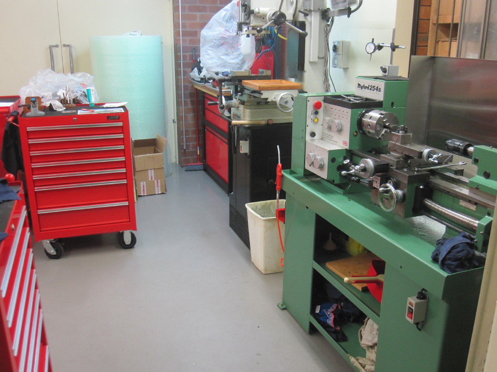 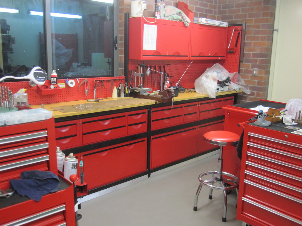
|
|
peteh
Statesman
  Still making mistakes!
Posts: 760
|
Post by peteh on Aug 18, 2017 13:41:03 GMT
Thursday afternoon had me wanting to walk into the desert and die an agonising death
Why is this so ?
I chipped the paint on a new Llewellyn frame I was assembling with Campy Record. So the Punter has to wait longer.
After dinner to make penance or a version of self flagellation I went into the Red Room and spent nearly 5 hours cleaning machines, sweeping floors and crannies and moped the floor, then oiled the machines. It was after 11pm to bed. Then up at 5 am to drive across Brisbane to drop the frame to the painter. Sigh! 5 steps forward and one step backwards. So tonight and tomorrow I get to work on the cylinders and steam chests in clean and fresh room. The next time you chip some paint you can do my workshop!   |
|
|
|
Post by steamer5 on Aug 18, 2017 21:52:25 GMT
Hi Daz,
I better not let SWMBO see those pictures! She will come & "help" me clean my shop!! Then I'll NEVER find a thing! What make are you cabinet?
Cheers Kerrin
|
|
jools
E-xcellent poster
  
Posts: 200
|
Post by jools on Aug 18, 2017 22:36:08 GMT
Hi Darren
just looking at the photos of the gland nuts, I can't help thinking that Brass Mikuni Carburettor main jets might be a good starting point......??
Many different sizes, shapes and threads.
|
|
|
|
Post by Oily Rag on Aug 20, 2017 21:01:15 GMT
|
|
|
|
Post by Oily Rag on Aug 20, 2017 21:03:26 GMT
Hi Darren just looking at the photos of the gland nuts, I can't help thinking that Brass Mikuni Carburettor main jets might be a good starting point......?? Many different sizes, shapes and threads. If you have them to hand, and you know the material and then if they fit the need, perhaps, however I have the raw PB stock on the shelf and can make to the drawings (my modifieed drawings) and it is fun. |
|
|
|
Post by Oily Rag on Aug 20, 2017 22:01:04 GMT
Saturday morning after I had done the shopping run I was sipping a strong Brownian Motion producer (a nice hot cup of tea) and I came across a an old dial gauge I have collected from my late father in law.
Then came an  I had been pondering the use of the simple height gauge I made for setting tool height on centre. This tool still required some dexterity of feel and a couple of facing test cuts in the lathe. I had been pondering the use of the simple height gauge I made for setting tool height on centre. This tool still required some dexterity of feel and a couple of facing test cuts in the lathe.
This is a hassle when a job is underway in the lathe and one wants to touch up the tool and refit. A wee while later and coupled to a lump of steel that was on hand, then a rub along the diamond Ezi Lap gave me a small elephants foot, a spunky tool height gauge is the result. Works a treat and will last my earthly days. I do not recall seeing this before but I am sure it has been done many times before and is a standard fitters tool ?  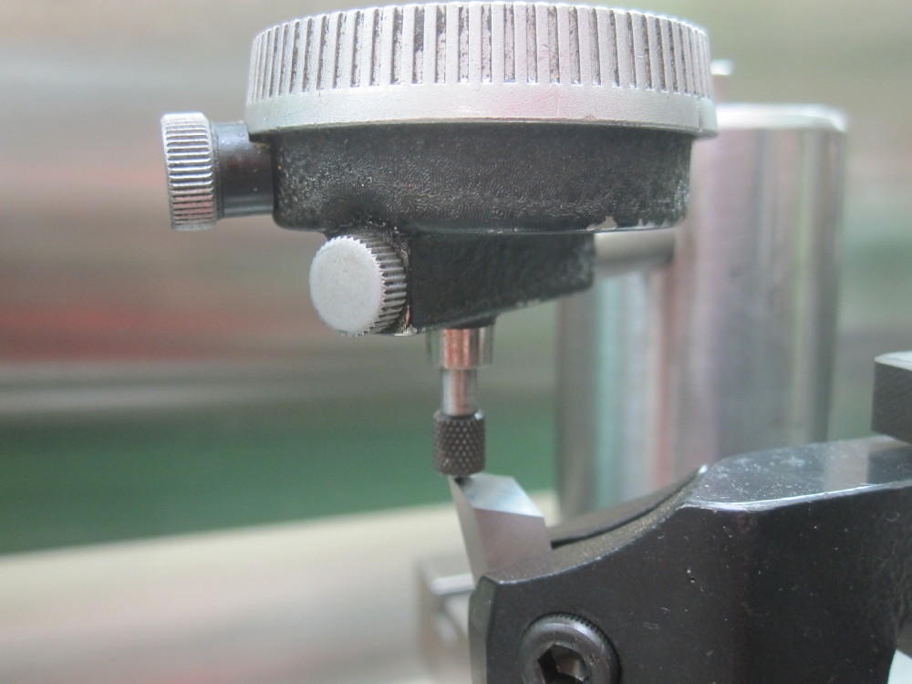 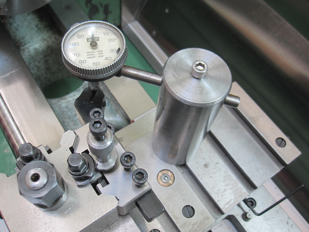 While I was feeling smug I pondered the 10BA studs for the steam chests and I desire a nice finish on the exposed ends. So following the success of the part/chamfer screw tool I set about making an adjustable stud part/chamfer screw tool from some chook scratchings. While I was feeling smug I pondered the 10BA studs for the steam chests and I desire a nice finish on the exposed ends. So following the success of the part/chamfer screw tool I set about making an adjustable stud part/chamfer screw tool from some chook scratchings.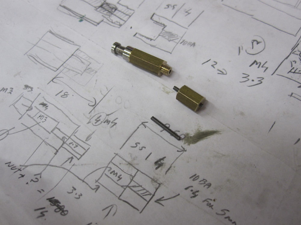 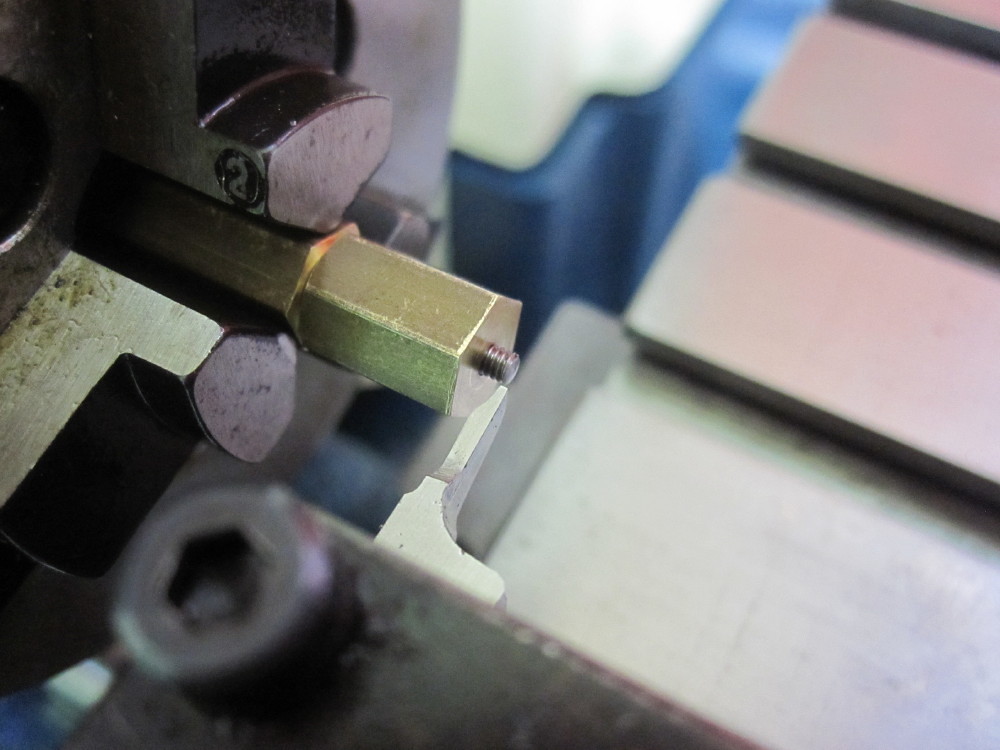 The design of Eric's valve gear as in the book has the reversing lever back when running forward. Being involved with full size choo choos I found this a hard to reconcile in my cranium, imaging the comments "Eh Dazza, you got that arse about...........................................", so last night I redrew the reversing gear linkages (3D) to have it to run forward when the reverser is forward. (which appears correct in the earlier Edwin design has but was changed in the Eric design) The design of Eric's valve gear as in the book has the reversing lever back when running forward. Being involved with full size choo choos I found this a hard to reconcile in my cranium, imaging the comments "Eh Dazza, you got that arse about...........................................", so last night I redrew the reversing gear linkages (3D) to have it to run forward when the reverser is forward. (which appears correct in the earlier Edwin design has but was changed in the Eric design)
|
|
jem
Elder Statesman
  
Posts: 1,075
|
Post by jem on Aug 21, 2017 17:08:18 GMT
Hi,
You must be reading my mine or the other way round, I have been thinking exactly the same thing, a clock height gauge! which is my next project. I have just finished a gauge for setting up on the 4 jaw, using the qctp to hold the gauge, rather than a magnetic base. then I made one for cylinders, and finally one for tapers. which makes setting up very much faster, and for tapers much more accurate. anyway photos to follow.
best wishes
Jem
nb I will put this into tools and tooling when I have the photoes.
|
|
|
|
Post by Oily Rag on Aug 24, 2017 21:37:59 GMT
Stainless piston rods, Clocked them up in the PB chuck. The brass shim is to avoid marking the surface. Screw cut the thread most of the way and chased with a die, the other end (cross head) was roughed out and then out came the shaving tool for the last .20mm, got them to 2.51mm. I did not chase the last .01mm to get to 2.50mm as I was afraid it might over cut as stainless is prone to do. 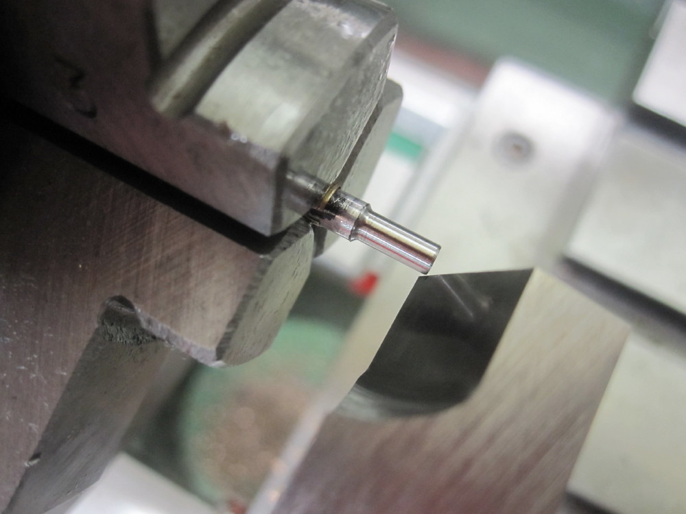 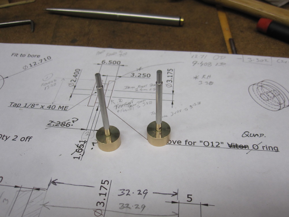 Fitted to the pistons now for the final machining, facing off to width and shaving tool on diameter and then the groove for the Quad ring. Fitted to the pistons now for the final machining, facing off to width and shaving tool on diameter and then the groove for the Quad ring.
|
|
|
|
Post by Oily Rag on Aug 28, 2017 21:37:31 GMT
Valve rod cross heads. Rodger would use his CNC wizardry but I have to do it the old way from some 3/8" square. I made some wee silver steel filing buttons with a 10 BA screw through them. I am yet to rub them down to 1500 grit. I like shiny motion, I detest painted motion rods. This is free lance so I free is the way I go :-)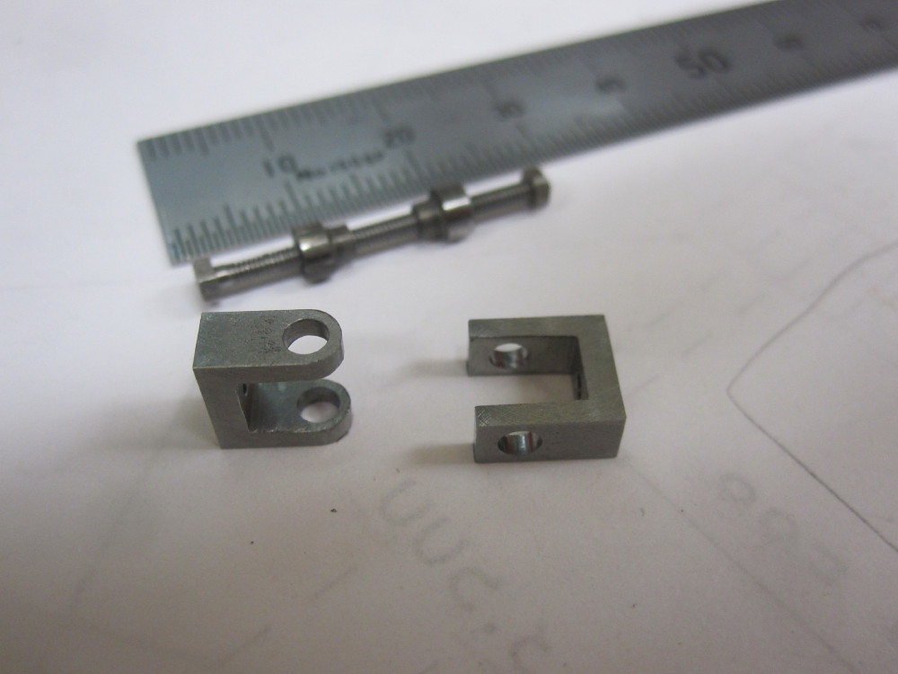 aimed for 4.00mm aimed for 4.00mm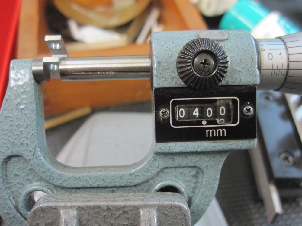 B. Wilsons drawings have 1.60mm stainless for the valve rods. Got that, to fit into in 1.60 holes into the chest and gland nut, yep. 10 BA thread on the end of the valve rod to pass the valve drive nut, however when the die is passed over the 1.60 is lifted to to 1.68mm diameter which is close to the correct 10 BA diameter according to my charts. But 1.68 will not pass through 1.60 holes. Sigh! Taking 0.80mm off a 10BA thread is leaving it a bit thin on the thread. One could open out the chest and grand nut to 1.70mm but the weight and movement of the valve rod and the combi lever and radius rod would all just be supported by packing, "errrrrr Yuk" (Errrrrr Yuk = Dazza technical term) B. Wilsons drawings have 1.60mm stainless for the valve rods. Got that, to fit into in 1.60 holes into the chest and gland nut, yep. 10 BA thread on the end of the valve rod to pass the valve drive nut, however when the die is passed over the 1.60 is lifted to to 1.68mm diameter which is close to the correct 10 BA diameter according to my charts. But 1.68 will not pass through 1.60 holes. Sigh! Taking 0.80mm off a 10BA thread is leaving it a bit thin on the thread. One could open out the chest and grand nut to 1.70mm but the weight and movement of the valve rod and the combi lever and radius rod would all just be supported by packing, "errrrrr Yuk" (Errrrrr Yuk = Dazza technical term)
So scrap the 10 BA idea. Thinking of metric 1.60mm thread (which tooling I do not have yet) or maybe a maybe a split nut with a pinch screw to close the nut onto the rod. A pinch screw directly onto the rod could make valve setting a woe due to the screw marking the rod making little 0.10 adjustments difficult and then marks on the rod make removal difficult and damaging to the chest and gland nut . I am yet to ponder more on this. I have a Australian Railway Historical Society QLD Division board meeting at our house tonight and going camping this weekend, so...........
|
|
|
|
Post by Oily Rag on Sept 4, 2017 3:02:35 GMT
Question to the collective Wisdom
I have a Myford 254S with a CAM lock spindle
Is there such an animal as a Lathe CAM lock fitting collect chuck for Er32 collets
or
do I really have to make some thing? A sort of camlock backing plate of use a face plate and rig some thing up ?
I could use 4MT chuck and draw bar but I would like to put long stock down the snout.
|
|
Lisa
Statesman
 
Posts: 806 
|
Post by Lisa on Sept 4, 2017 3:42:15 GMT
|
|
|
|
Post by Oily Rag on Sept 4, 2017 20:46:24 GMT
Oh yes, YES, but I think the Myford 254s is a D1-3 cam lock, I may have to find a blank D1-3 cam lock and mate it with a collet chuck with a blank back plate. |
|
davidk
Active Member
 
Posts: 32
|
Post by davidk on Sept 4, 2017 21:27:20 GMT
I don't know about ER32, but last year I bought an ER40 D1-3 cam lock collet chuck from Gloster Tooling. Might be worth contacting them. Usual disclaimer etc...
David
|
|
|
|
Post by Roger on Sept 4, 2017 21:51:37 GMT
I bought my ER32 collet chuck and a separate Camlock mounting plate from Warco.
|
|