rrmrd66
Part of the e-furniture

Posts: 339 
|
Post by rrmrd66 on Oct 18, 2017 6:56:59 GMT
Hi David
Just make sure that you nail the spec down exactly as you want it.
Demand a written order acknowledgement before you take delivery (mine arrived without the DRO)
Suggest you read my post in "Tools and Tooling".
Caveat emptor
Regards
Malcolm
PS The Super Major Vario is a big lump on top of a light weight box and needs 2-3 people plus 1 ton engine hoist to install. Think about self leveling HD anti vibration pads for the feet if you do not want to drill into workshop floor.
|
|
jools
E-xcellent poster
  
Posts: 200
|
Post by jools on Oct 18, 2017 11:01:04 GMT
Hi Malcolm,some nice work and progress there. I too have a vertex rotary table identical to yours. I have always had problems fixing work to be concentric to the centre for accurate radius machining - I was unaware the centre hole was an MT2 taper ! What I am searching for now is a an MT2 taper shaft with a tapped end to allow me to use this as the mounting reference for work. Did you manufacture your tool shown or was it purchased ? I would be interested to know where you sourced it if so. cheers Jools Hi Jools Try this: www.rdgtools.co.uk/acatalog/ADAPTOR-FOR-ROTARY-TABLE-6--MYFORD-THREAD-898698.htmlor this maybe: Chronos ref BEA2T The MT2 arbor fits into the Myford spindleas well butmaybe you know this.Useful for turning wheels and then transferring to the Verte without disturbing the eccentricity (or lack of it) Cheers Malcolm Many thanks for the link Malcolm, Unfortunately not owning a Myford, I would need to make an adaptor to suit my Hafco rig. I'm assuming this thread fits the standard Myford chuck ? The other option then could be to possibly source one of those just for this purpose. cheers Jools |
|
rrmrd66
Part of the e-furniture

Posts: 339 
|
Post by rrmrd66 on Oct 20, 2017 7:31:46 GMT
Hi Jools Have a look at this: www.arceurotrade.co.uk/Catalogue/Adaptors-SleevesCan you not get a cylindrical sleeve in your lathe chuck/spindle, with an internal MT2 bore , then turn up the end detail and then transfer it to the Vertex MT2 bore? Good luck. Malcolm |
|
jools
E-xcellent poster
  
Posts: 200
|
Post by jools on Oct 22, 2017 22:29:05 GMT
Hi Malcolm,
another good link - might be able to find what I need here, no urgency as I got around the problem by machining a two piece bms mandrel and dolly so I could mount the part for machining in the lathe. The concentric runout had to be neglibible as its a rear wheel drive sprocket carrier and contains an outboard bearing for axle load.
I would need to use the drawbar MT2 type adaptor on the Vertex I guess, to keep it in place.
I was not sure that my lathe had an internal taper spindle, but according to the Chester manual (nearest equivalent to the Hafco AL300) it mentions MT5 and checking without removing the chuck using inside calipers does confirm there is a taper in there which is nice to know.
The spindle spigot is 2" 8TPI which fits all of the chuck back plates that I have.
cheers for all the help
Jools
Jools
|
|
rrmrd66
Part of the e-furniture

Posts: 339 
|
Post by rrmrd66 on Nov 20, 2017 21:15:23 GMT
Good evening everybody. A few weeks since I last brought you up to date. I have been very busy on this project although there seems to be glacial progress. I average about 25-30 hours a week. There is a lot of time waiting for materials and tools to arrive. However no excuses so onto the build. The eccentric connecting rods have now been braised and are being finished machined to arrive at the correct distance between the expansion link bush and the face of the eccentric strap. The drill bit stuck in the hole allows me to set the exact distance wit the help of the DRO. 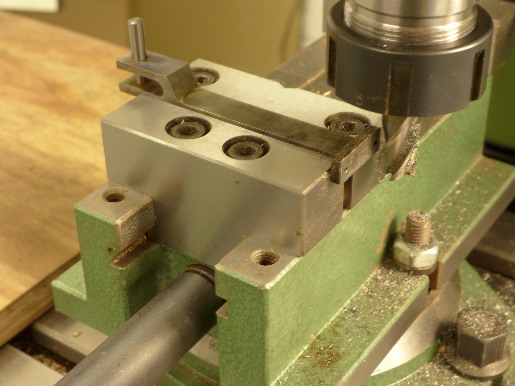 P1010202 P1010202 by Malcolm HARWOOD, on Flickr The connecting rods lenghts are all within +/- 0.0025" so I think that good enough The oil reservoirs and lubrication passages have been drilled. 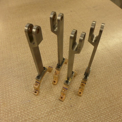 P1010209 P1010209 by Malcolm HARWOOD, on Flickr Next we move on to the intermediate valve guide spindles. Here is one mounted in the 3 jaw chuck in the rotary table with the far end supported by the tail stock and an extra 1/2" of thread with a centre drill which I will remove later. I was uncertain that drilling and milling this "free" end was a good idea unsupported. The chuck is held in the rotary table by an 2MT adaptor which allows the use of the Myford chuck Very good. However, the disadvantage is that the work piece can only be fed into the chuck until it meets this adaptor. I noticed that Roger and Speedy has such a Vertex Rotary table and tailstock. His clamping arrangements are the opposite to mine. I have to clamp the table with straps whereas the tailstock sits nicely in the centre groove of the milling table. Roger's is the opposite. By the way. Not all "H6" rotary tables are of Vertex manufacturer. Some suppliers use this designation but do not make it clear that they are from other suppliers. Shame on them! The horrendous burr and the very short end mill are the result of a minor accident. I broke the cutter! 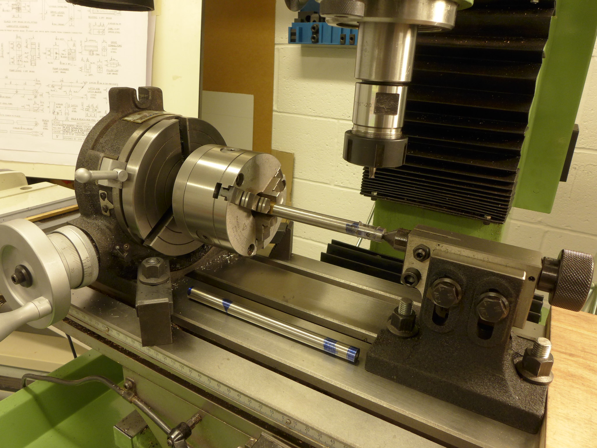 P1010210 P1010210 by Malcolm HARWOOD, on Flickr One end of the valve spindle is now more or less finished the other needs its "center drill hole" removing and the clevis end radiussing. 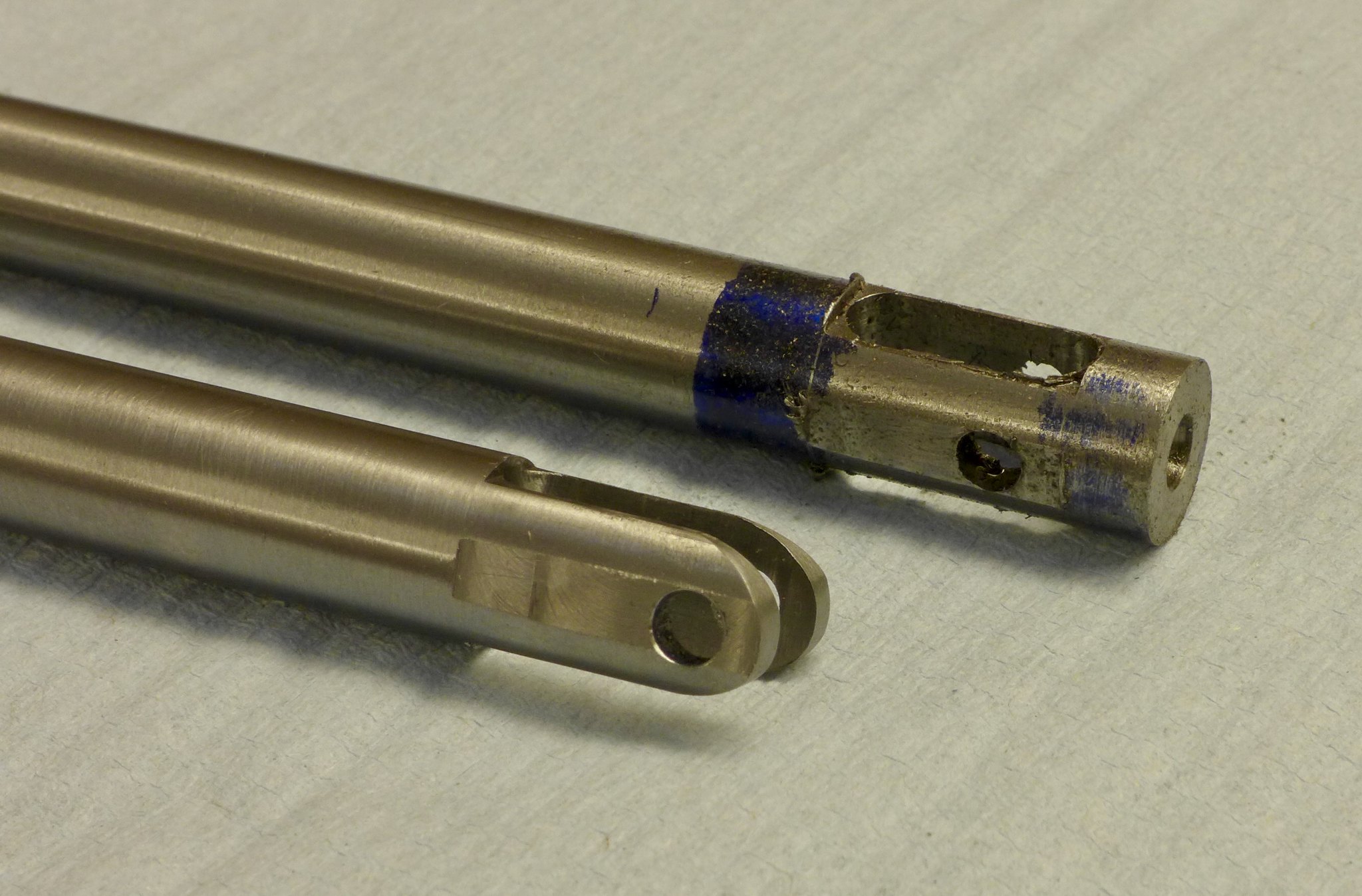 fullsizeoutput_668 fullsizeoutput_668 by Malcolm HARWOOD, on Flickr Returning the valve spindle to the lathe allows the 5/16" waist to be turned and the newly acquired button tool to turn the radiused shoulders. The extended thread can now be removed and the overall dimension checked against the drawing. 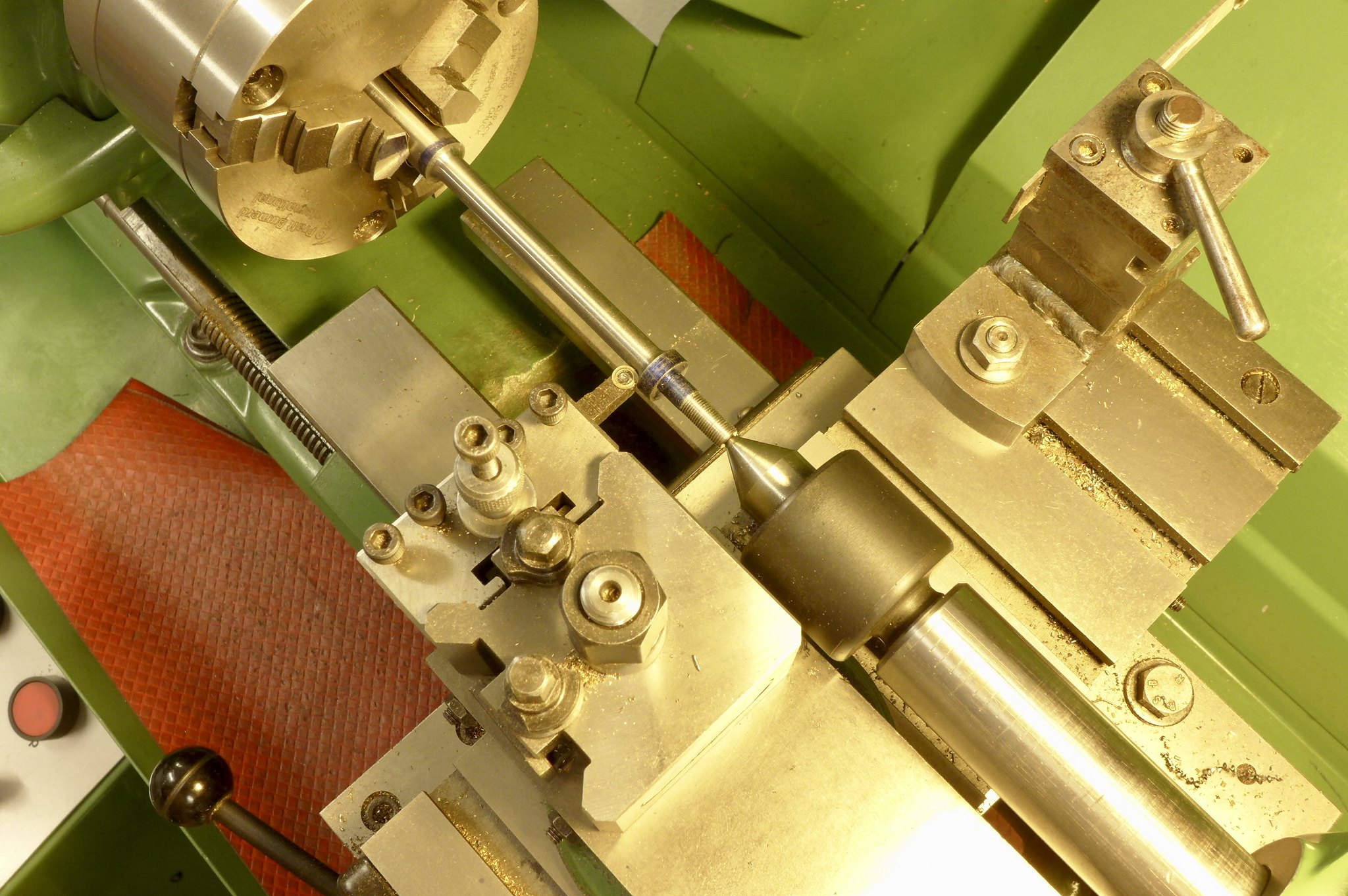 fullsizeoutput_66f fullsizeoutput_66f by Malcolm HARWOOD, on Flickr Whilst waiting for some other part I make a start of the lifting and reversing arms and links. Here I have "gang marked" them out to ease drilling prior to cutting and shaping 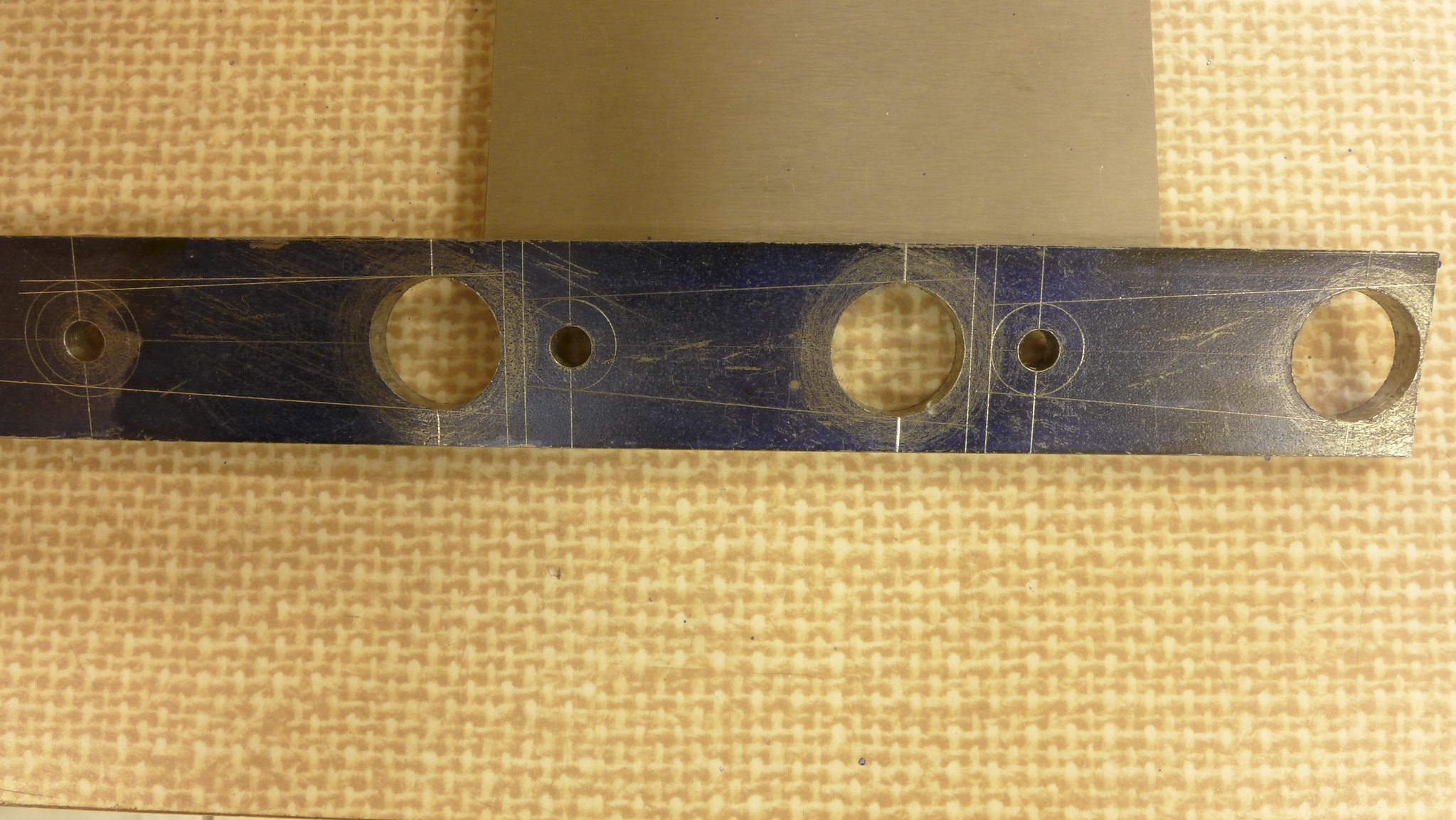 P1010204 P1010204 by Malcolm HARWOOD, on Flickr Brazing jigs have been made for the lifting arms (2 off at 1 9/16"centres ) and the reversing arm (1 off at 1 3/4" centres). The lifting arms are to the Bill Hall optimised dimension, not the Don Young dimension. (1/16" difference). The lifting links are to drawing. 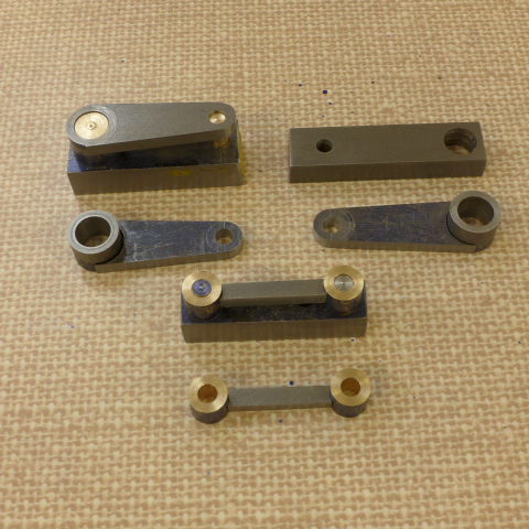 P1010208 P1010208 by Malcolm HARWOOD, on Flickr I am trying to get the complete valve gear assembly made so make a start on the cab mounted pole reverser. I need to locate the exact centre of the rotary table with respect to the spindle centre. I have not got one of those gadgets, at present, for mounting the DTI in the chuck to centralise it. Thus I make a brass button that fits into the center bore and align the spindle/rotary table by eye (i am only cutting quadrants remember) 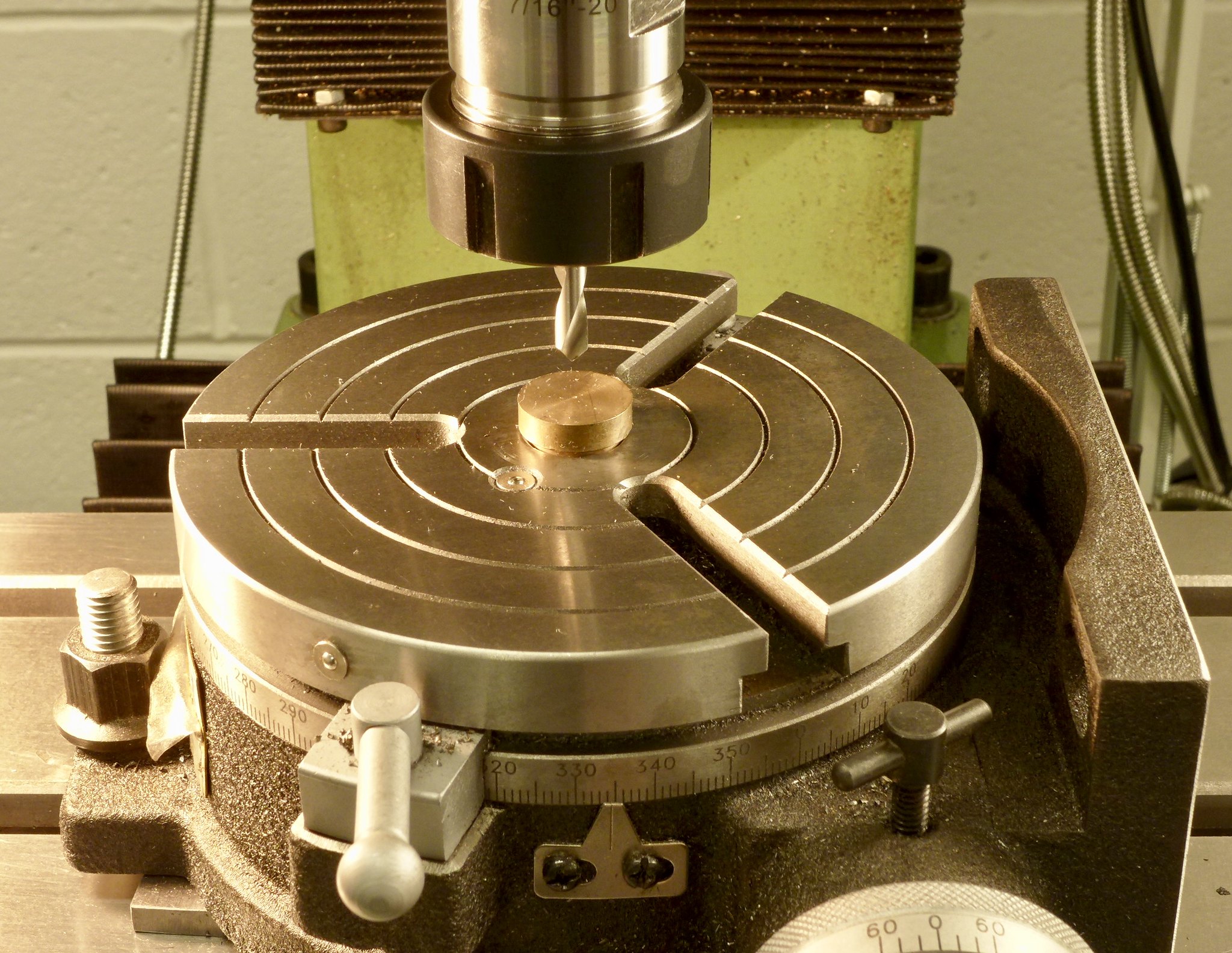 fullsizeoutput_66d fullsizeoutput_66d by Malcolm HARWOOD, on Flickr Next I take apiece of 1/8" plate and mark out the three quadrants. The two large ones for the reverser pole. The small one for the cylinder drain cock lever. I seem to have run out of small wood screw so try to make do with just three. With the help of the DRO I can set the end mill at exactly the correct OD and ID. 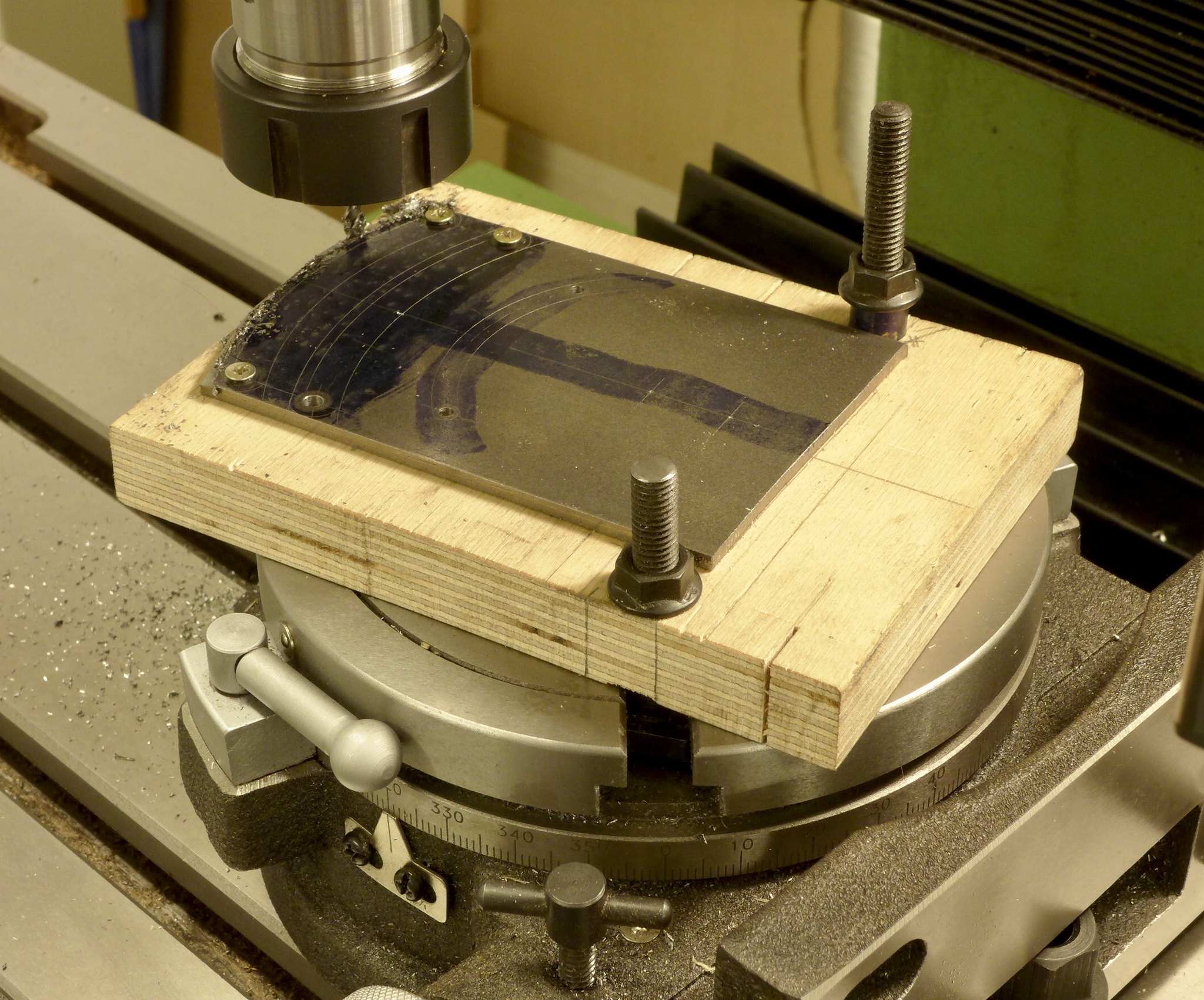 fullsizeoutput_669 fullsizeoutput_669 by Malcolm HARWOOD, on Flickr Maybe not such a good idea.. I manage to cut the two larger quadrants, but only just. There is an OD and ID to cut. The OD is fine, but the ID, unless the cutter is fed in from the opposite end is climb milling. The quadrant pings harmlessly out of its minimal fixture. The small quadrant is cut correctly with just about everything screwed down. The two larger ones, cut earlier, are there just for the picture. Note that flat on its back the bolt holes do line up nicely. 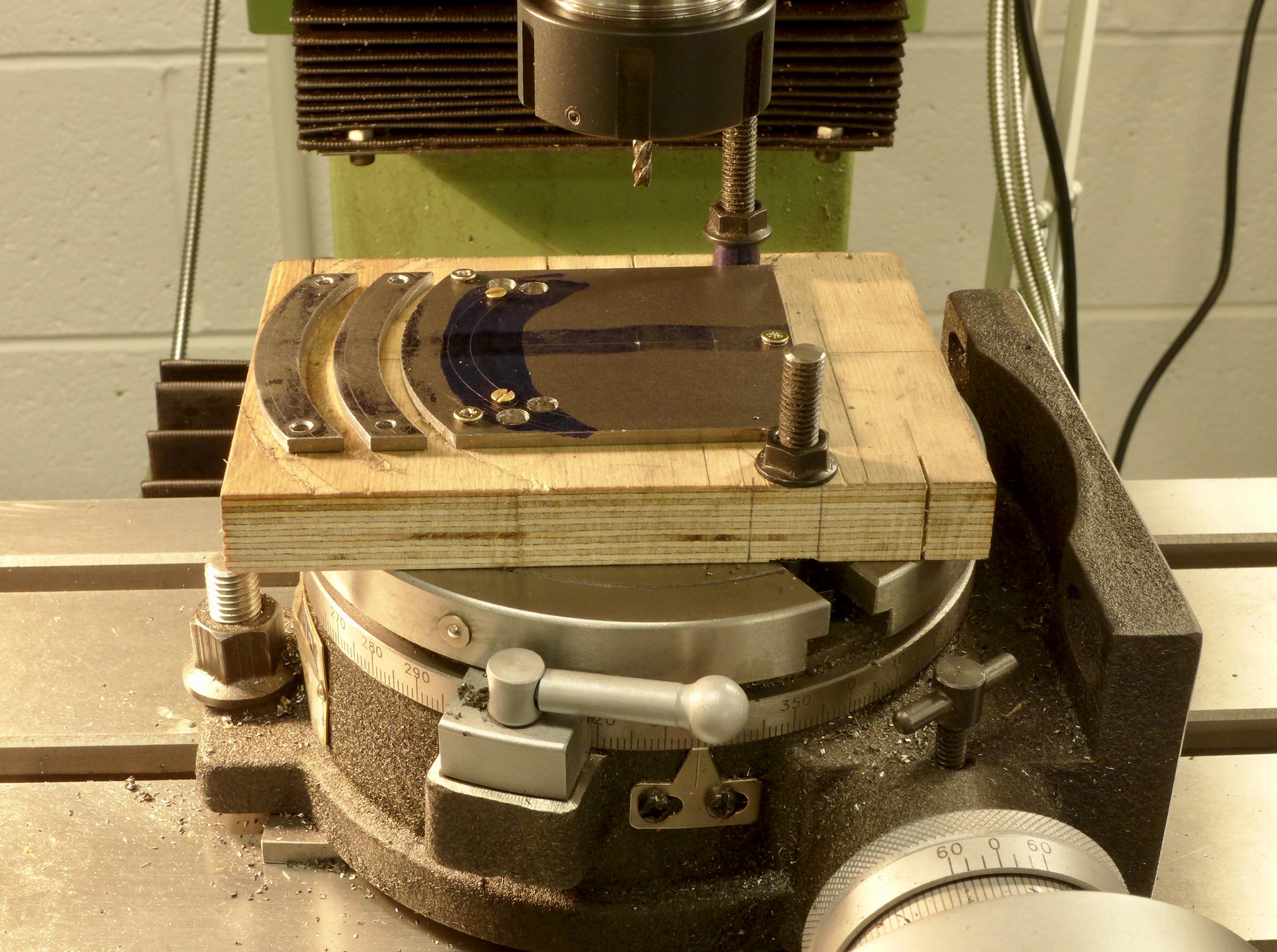 fullsizeoutput_66c fullsizeoutput_66c by Malcolm HARWOOD, on Flickr I will include pictures of the rest of the pole reverser in my next post plus the dreaded expansion link and die block. Thanks for reading. Cheers Malcolm |
|
|
|
Post by simplyloco on Nov 20, 2017 22:09:55 GMT
My goodness: very nice, but those setups are the cleanest clean I've ever seen! Where does the swarf go?
John
|
|
rrmrd66
Part of the e-furniture

Posts: 339 
|
Post by rrmrd66 on Nov 21, 2017 7:27:08 GMT
Hello simplyloco
Into a dustpan.
I have a thing about 'mucky working"
Cheers
Malcolm
|
|
|
|
Post by ilvaporista on Nov 21, 2017 7:57:17 GMT
For the jobs where a moderate amount of precision is required I have a quick and dirty method of setting the rotary table axis in line with the spindle. I have turned piece of true-running ground bar machined to a 30 degree included angle point (the exact angle is irrelevant..). Put that in your milling chuck (of course use a bar with the diameter you have a collet/holder for, mine was 20mm). Leave the rotary table loose, bring down the point into the central hole in the rotary table and it will centre itself up on the point. Don't force it into the hole, a light contact is all that is necessary. If the rotary table is large and heavy moving the slides is the best way. I find that the small 5" table moves easily on its own, the 8" is too heavy. Tighten up the clamps of the rotary table and zero all dials.
It's taken me longer to write than to do the job and it's accurate for 99% of the jobs I do.
|
|
rrmrd66
Part of the e-furniture

Posts: 339 
|
Post by rrmrd66 on Nov 21, 2017 16:34:26 GMT
For the jobs where a moderate amount of precision is required I have a quick and dirty method of setting the rotary table axis in line with the spindle. I have turned piece of true-running ground bar machined to a 30 degree included angle point (the exact angle is irrelevant..). Put that in your milling chuck (of course use a bar with the diameter you have a collet/holder for, mine was 20mm). Leave the rotary table loose, bring down the point into the central hole in the rotary table and it will centre itself up on the point. Don't force it into the hole, a light contact is all that is necessary. If the rotary table is large and heavy moving the slides is the best way. I find that the small 5" table moves easily on its own, the 8" is too heavy. Tighten up the clamps of the rotary table and zero all dials. It's taken me longer to write than to do the job and it's accurate for 99% of the jobs I do. Yes good idea. Not so different to my method really. Skinning cats, eh? Thanks for the tip. Malcolm |
|
|
|
Post by ilvaporista on Nov 22, 2017 10:21:47 GMT
Yes the poor cat has had more skinnings than it's nine lives.. I've learned so much off other people's posts and having seen your pictures I am trying to get myself to work in a cleaner environment.
|
|
rrmrd66
Part of the e-furniture

Posts: 339 
|
Post by rrmrd66 on Nov 22, 2017 12:11:12 GMT
Praise indeed from an "Elder Statesman".
I am honoured, sir.
Cheers.
M
PS I do take a certain amount of time to "dress the set" before pressing the button!
|
|
dscott
Elder Statesman
  
Posts: 2,440
|
Post by dscott on Nov 22, 2017 23:09:12 GMT
Now you need to bore out a large diameter hole in the slab of bracket to make it authentic
and lighter.
Plus don't forget just 2 holes for fixing bolts as per the original at the ends.
The draincock lever being a bit of 1/4 by 1/16 steel with an L bent on the end to hold it by.
Simple slot in the cab front for it to fit through!
As I have said before Don loved to add extra detail with a chuckle so that builders would
have to drill 3 extra unnecessary holes!!!!!!
|
|
rrmrd66
Part of the e-furniture

Posts: 339 
|
Post by rrmrd66 on Nov 23, 2017 8:33:00 GMT
Hi David
Have you more detail about the "large diameter hole" in the pole reverser bracket?
I had an interesting hour with the guys at the Lake Bala NG Railway in their shed a few weeks back where they have 4 or 5 Hunslets of one type and another. Took lots of pictures but not from that side of the cab. Sod's Law eh?
Although I am all for a mod not too sure about the draincock rod. I like levers and bellcranks. Remember this time last tear I was finishing off an 8 day Grandmother clock movement and case.
Enough of my meager efforts. Did you buy that milling machine? If so we would all like to see pictures and details please.
Thanks for your interest
Regards
Malcolm
|
|
dscott
Elder Statesman
  
Posts: 2,440
|
Post by dscott on Nov 25, 2017 0:41:02 GMT
Hi Malcolm,
Yes, we drove over to Warco and missed one for a few pounds less... But it was 3 Morse taper and needed to go in the car!!
Bought too many things including a copy of the auto-lock chuck in metric R8! Got home and the collets slipped into my 2 MT
Titanic without a wobble?
Met up with Roger in the collection of eager buyers there!
I must dig out the stand!
Don Young designed the locos but I suspect he never got round to a build? His Black Five has about 30 odd bolts holding the
smokebox in place!!! Careful machining put them all in but as dummies. 4 Allan bolts from underneath and it is fitted or
unfitted in moments!
|
|
rrmrd66
Part of the e-furniture

Posts: 339 
|
Post by rrmrd66 on Nov 26, 2017 7:43:59 GMT
Hello David
Bad luck missing the milling machine.
Would still appreciate stand detail if you can find it.
Regards
Malcolm
|
|
rrmrd66
Part of the e-furniture

Posts: 339 
|
Post by rrmrd66 on Dec 15, 2017 20:32:40 GMT
Good Evening. Once again daily effort appears to have produced not much progress. However, lets get up to date with this "simple" build. Some time ago Julian Atkins offered to run the valve gear control assembly through one of the optimised spread sheets. The one he chose was Prof Bill Hall's. The adjustment to the dimensions of some of the expansion link/trunnion/lifting arm assemblies were minor but having fought my way though Don Ashton's treatise upon Stephenson's Valve gear I decided to give it a go. Dear old Don Young, the designer of this Hunslet NG engine, decided in his haste/wisdom(?) to make 1"+3 5/8" = 4 7/8". This of course should be 4 5/8" and so the expensive water jet cut expansion links supplied by a company, most people on this forum hold in high regard, was not able to have them re-cut to the new dimension. Fortunately, when you have run a seal manufacturing and distribution company for 25 + years then you do have a few contacts who are still good friends. One such ex employee now works for an international company deeply involved with sealing in the petrochemical industry and has all sorts of wonderful machine at his disposal. Thus below, on the left hand side of the picture, we have an expansion link and die block machined by what I call "spark erosion" ,but it's posh name is EDM (electrical discharge machining) The results are plain to see. The expansion link on the right is the water jet cut original version. As you can see the die block has been also EDM machined to a matching radius and runs very smoothly in the expansion link. They also kindly put the rivet holes in for me. I have fitted the P.Bz bearings. Incidentally the lifting arm trunnion, in its partly machined state, has what I have dubbed the "Atkins shoulder". A tip from Julian to help locate the trunnion whilst spotting through to drill the 3/32`' rivet holes. 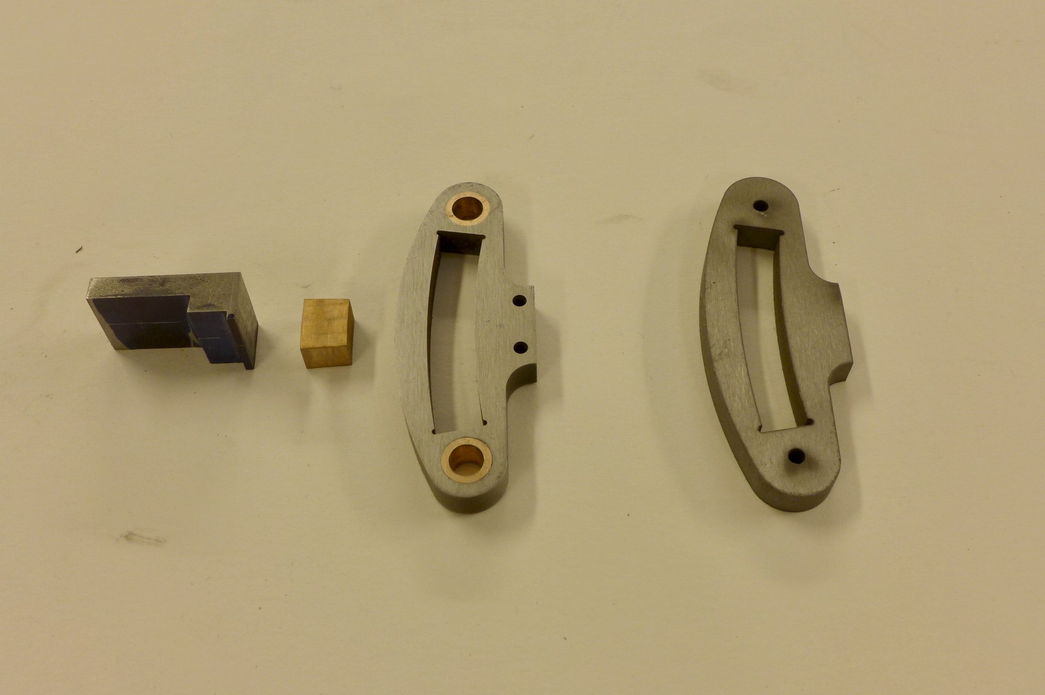 fullsizeoutput_672 fullsizeoutput_672 by Malcolm HARWOOD, on Flickr The die bock is in fact quite small. 1/4" thick and 13/32" in length. It needs a 3/16" dia. hole to take the pin that fixes it to the intermediate valve spindle and as I only had one per link I thought that this was one of those ideal opportunities to make a big mistake. I found the center on the surface plate with my height gauge, made an improvised clamping arrangement from wood and screws and centred it by with a centre drill prior to drilling. The SOBA drill vice whist being cheap is unfortunately not that accurate and tends to clamp untrue in its jaw shoulders. I should point out that the wording on the drill tin is nothing to do with my affiliation to a certain southern soccer team. 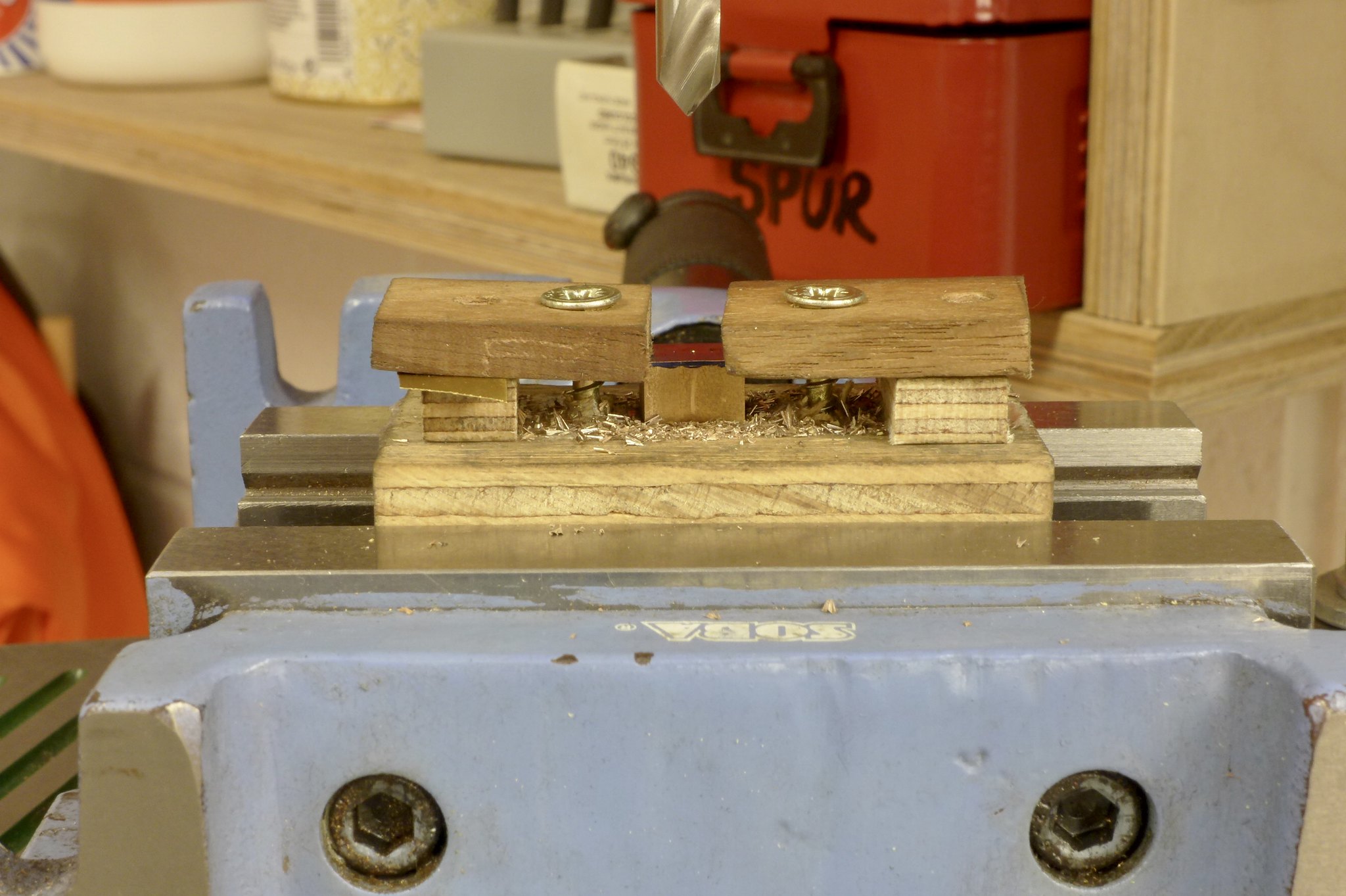 fullsizeoutput_673 fullsizeoutput_673 by Malcolm HARWOOD, on Flickr The outcome of all this waffle is that I now have two edm expansion links, together with die blocks, and two trunnion arms that have been modified to place the centre of the pin about 0.100" in front of the center line of the radius slot ( to the right of the bisected line if you are interested) plus rivet holes drilled wit the assistance of the Atkins shoulder. 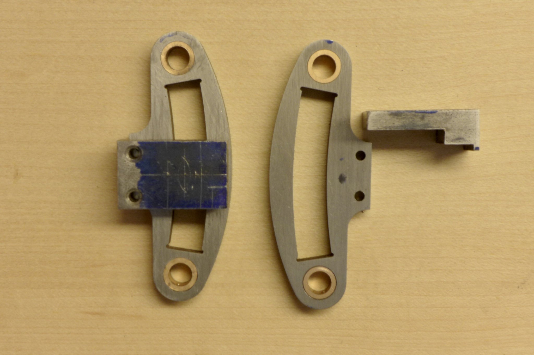 fullsizeoutput_674 fullsizeoutput_674 by Malcolm HARWOOD, on Flickr Eventually after much fettling, filing and soldering we have a kit of parts with which to put the sub assembly together. Here we see work in progress. The int. valve spindle in pinned by an interference fit pin. The hidden die block is free to move on the pin and slide in the slot. Next step is to join the eccentric strap con. rods to the ends of the expansion links and Robert is your uncle. I will report back in due course 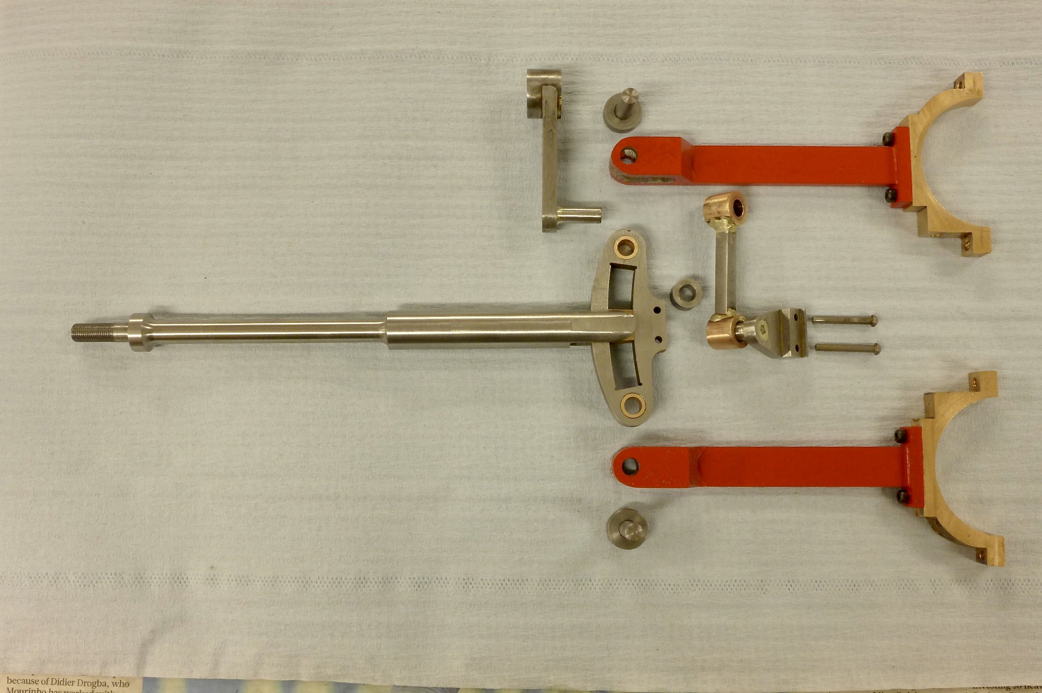 fullsizeoutput_675 fullsizeoutput_675 by Malcolm HARWOOD, on Flickr Thanks very much for reading my ramblings Cheers Malcolm |
|
jools
E-xcellent poster
  
Posts: 200
|
Post by jools on Dec 15, 2017 23:09:46 GMT
Beautifully engineered that is Malcolm.
|
|
rrmrd66
Part of the e-furniture

Posts: 339 
|
Post by rrmrd66 on Dec 16, 2017 8:15:04 GMT
Thanks Jools
I need all the encouragement I can get!
Malcolm
|
|
jma1009
Elder Statesman
  
Posts: 5,922
|
Post by jma1009 on Dec 16, 2017 23:06:50 GMT
Hi Malcolm,
You have done very well there! Excellent work and progress!
Sorry to have created extra work for you, and expense in ditching the original laser cut expansion links, but as a result you will have a very good loco on the track performance wise.
Cheers,
Julian
|
|
rrmrd66
Part of the e-furniture

Posts: 339 
|
Post by rrmrd66 on Dec 17, 2017 8:03:26 GMT
Hello Julian
Thanks for the nice words.
We might just as well use the power of modern technology if it helps (i.e. computer spread sheets).
There is a wonderful black and white photo somewhere of two draftsmen working on a full size valve motion simulator at one of the loco works in the 30's(?). Somebody will know the one I refer to?
A bit like the wonderful piece of furniture that the NRM has in their storeroom used to signal men. More Chippendale than Gresley.
Cheers
Malcolm
|
|