|
|
Post by springcrocus on Dec 17, 2017 9:51:56 GMT
This one?  Regards, Steve |
|
rrmrd66
Part of the e-furniture

Posts: 339 
|
Post by rrmrd66 on Dec 17, 2017 10:14:27 GMT
|
|
rrmrd66
Part of the e-furniture

Posts: 339 
|
Post by rrmrd66 on Jan 10, 2018 16:16:17 GMT
Evening all Progress on the Hunslet build. The two sets of Stephenson's valve gear is more or less finished, as shown below, mounted on dummy shafts. The DY drawings are not too helpful in reassuring me that this is assembled correctly. However Hunslets for sale on the internet (Station Road Steam is good) have good close ups of all parts of these engines, so I think this is OK. Just a few rivets to finish and a few split pins to fix . There is a lot of fitting and "easing" to be done to get everything moving smoothly. 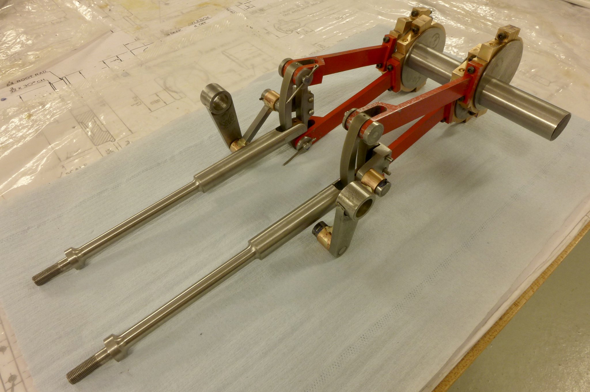 fullsizeoutput_677 fullsizeoutput_677 by Malcolm HARWOOD, on Flickr The pole reverser is a treat if you like making small intricate mechanisms. This is as far as I have got. I am leaving the notches until I see where full forwards and full reverse is when the reach bar is finished (currently under manufacture). Again a lot of fitting to be done on this. The leaver and guide bars at the base of the unit are to drawing and for the cylinder drain cock actuator rods. 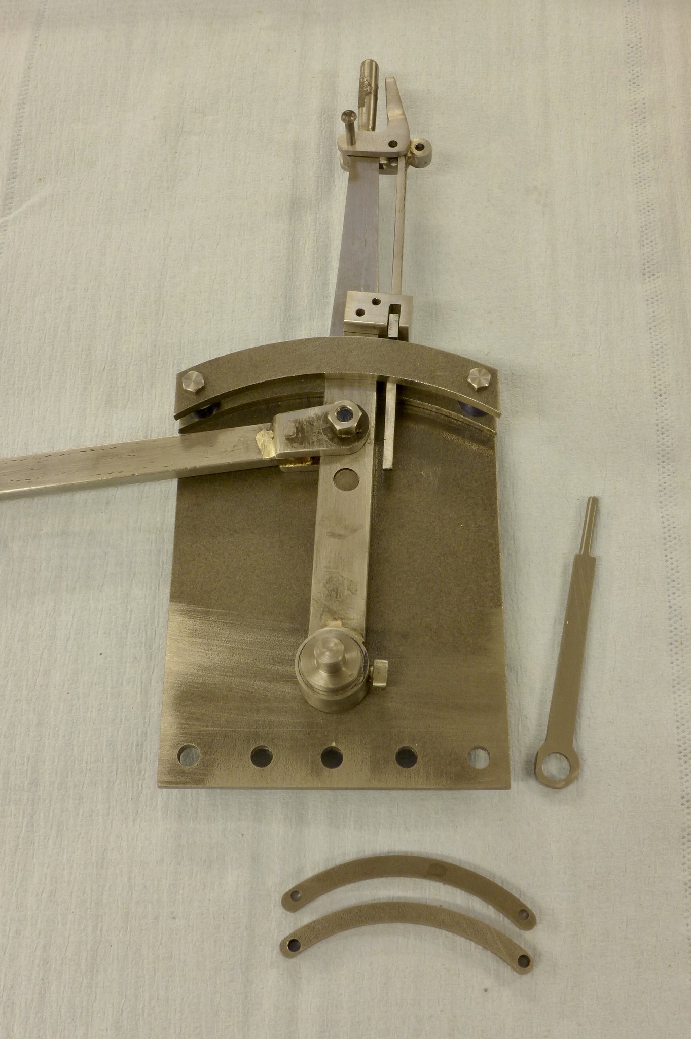 fullsizeoutput_679 fullsizeoutput_679 by Malcolm HARWOOD, on Flickr Almost to the point of mounting the valve gear into the frame and see if it all fits. I hope so! You can see one half of the reach rod, which I think has to mounted outboard of the frame. Not as I have it hear. There has recently been some threads about rotating build stands. This is my attempt at one made from two Machine Mart 1 ton car jacks ( over specified but cheap). Apologies to all the advanced manufacturing fraternity. This is based on the teachings of Professor Miuayga* of Tokyo School of Advanced Technology The DY Hunslet has dumb wooden buffers and countersunk wood screw holes on the buffer bars.The build is taking place in what is my furniture workshop ans so there are all sorts of bits of wood kicking about hence the oak plummer blocks! The engine can be raise and lowered with the hook seen lying on the base board and mounted in a hand held electric drill if speed is needed. The 8x45 degree rotary stop needs a little finessing but works fine. 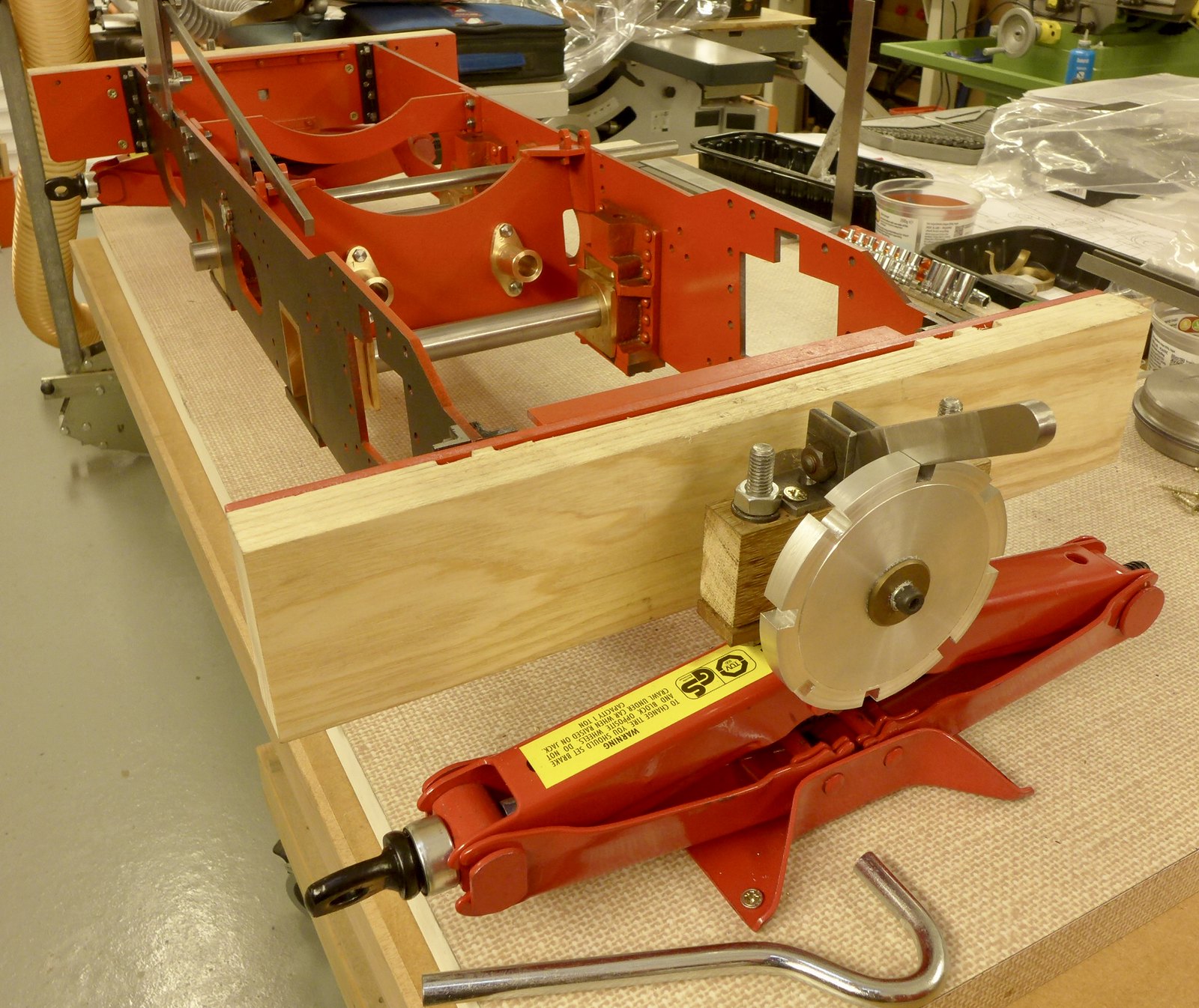 fullsizeoutput_67b fullsizeoutput_67b by Malcolm HARWOOD, on Flickr This is a view from the other end of the build stand showing the reach rod being "eyed up" prior to cutting to length 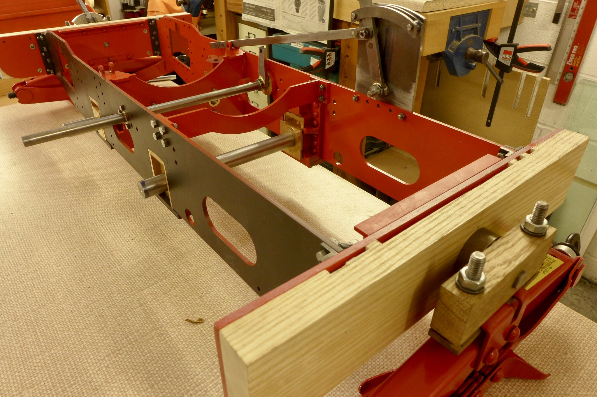 fullsizeoutput_67c fullsizeoutput_67c by Malcolm HARWOOD, on Flickr Next to do after fitting the valve gear and making sure it all lines up is to make a start of the valve chests and cylinders. I think I can then at last finally drill the frames and fit the valve motion plate. Thanks for reading cheers Malcolm Miuayga* (Make It Up As You Go Along) |
|
rrmrd66
Part of the e-furniture

Posts: 339 
|
Post by rrmrd66 on Feb 3, 2018 14:00:25 GMT
Afternoon Chaps and Chappeses ( are there any female model engine builders by the way?) Progress report on the Hunslet build. This is a bit of a milestone for me . I had to have a trial fit of the eccentric valve gear, expansion link, die block weight shaft and reversing lever just to see if I was going in the right direction. Although a little stiff, it all appears to work OK. You will note the inside motion plate is ready to go on. However I cannot fit it to the frames yet. It locates in those three pairs of off set screw holes to the left the front axle, and it all has to line up with the valve chest spindle which is yet to be done, along with the cylinders. It would appear that there will have to be a little relieving carried out by the horn block casting. The laser cut motion plate has tabs to aid construction but they will be in the way after silver soldering and will have to filed off prior to final fitting. Still a big step forwards for me. 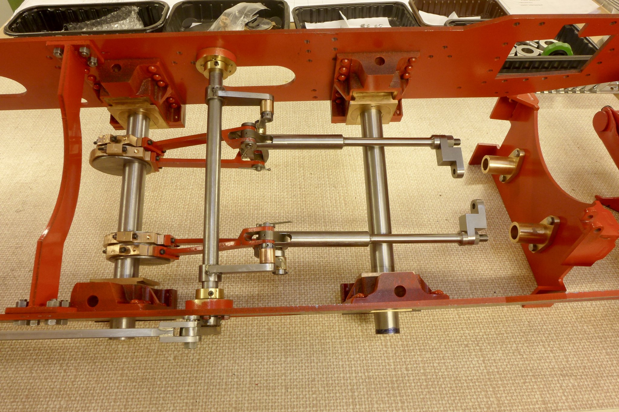 fullsizeoutput_67f fullsizeoutput_67f by Malcolm HARWOOD, on Flickr The pole reverser assembly is finished apart from closing the rivets and painting. I have been advised (by Julian, thanks BTW) not to cut the slots for the latch until I have the pistons mounted in the cylinders and I can then determine BDC and TDC, or whatever you guys call it. Locating holes for the tension spring are there and I have a spring ready to go on. The linkage for the cylinder drain cocks will have to come later. Probably a good idea not to finalise all the fixings until the very end. 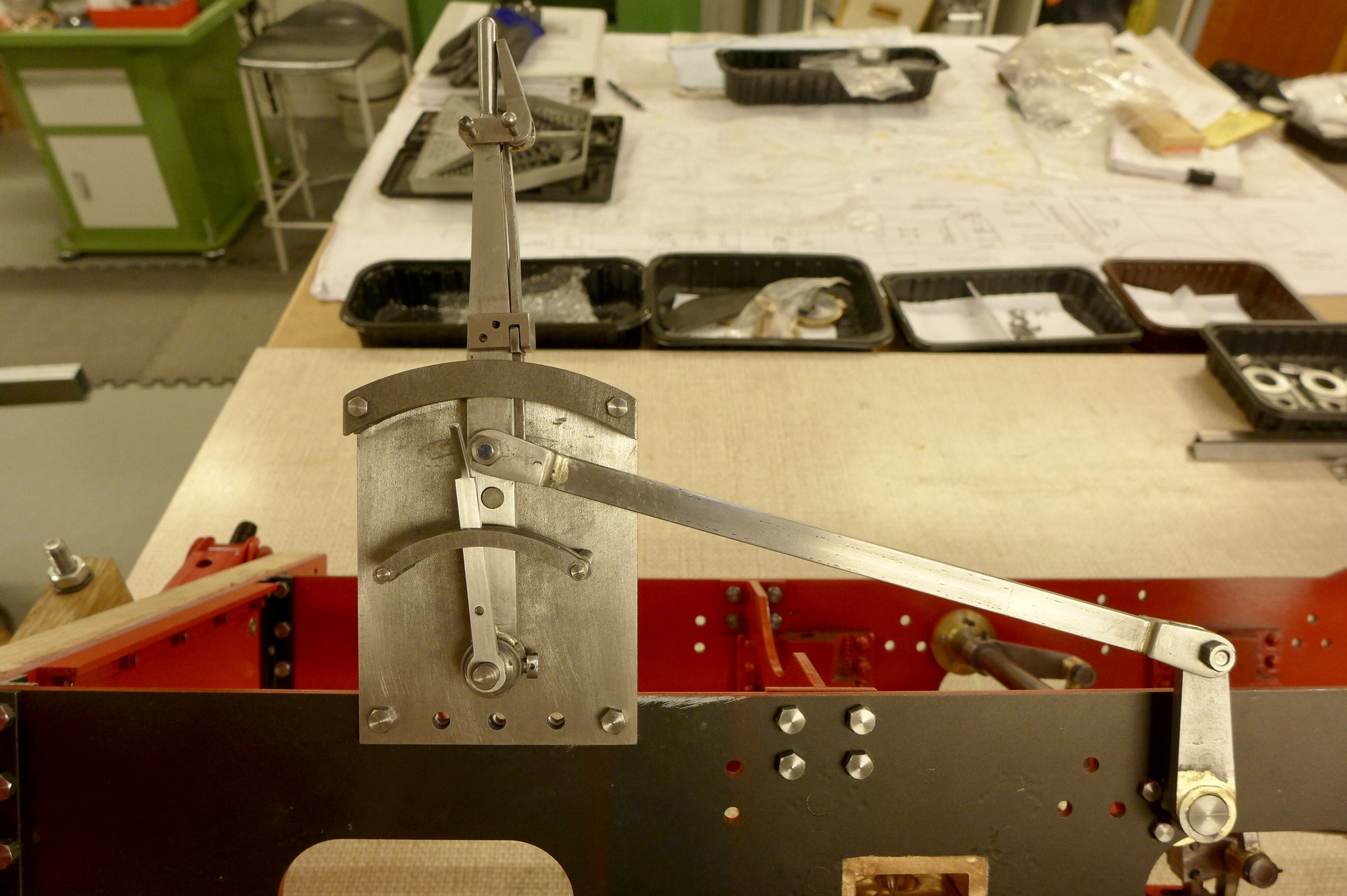 fullsizeoutput_680 fullsizeoutput_680 by Malcolm HARWOOD, on Flickr Moving on to the coupling rods you will see that I have sourced laser cut parts. This is very helpful in reducing construction time. However, there is always a down side and this manifests itself in the ugly cutting mark left by the laser. The localised heat gives a hard skin (reminds me of induction hardening) and also a slight taper across the face. What does everybody else do? Remove or ignore? 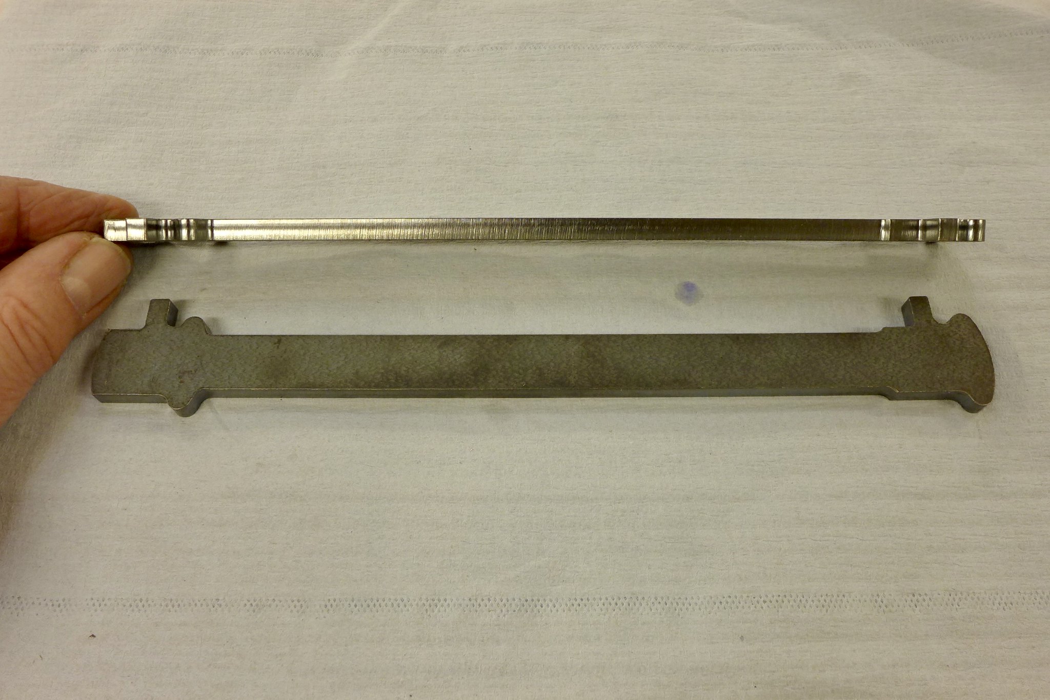 fullsizeoutput_681 fullsizeoutput_681 by Malcolm HARWOOD, on Flickr In the end i reverted to good old draw filing plus emery. I don't know if this makes a huge difference as the rods will be painted and the laser cut marks would not be seen. But, I guess, I will always know that they are there. 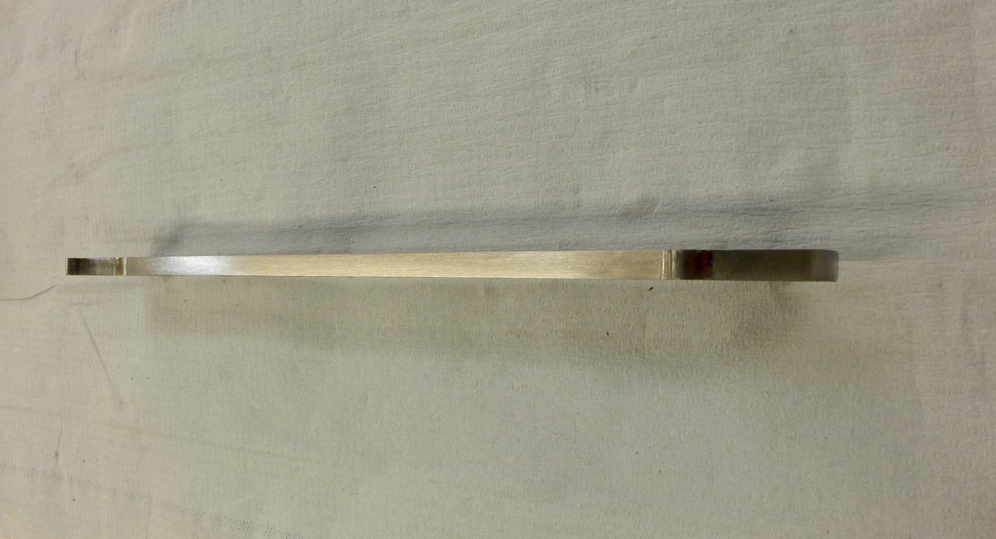 fullsizeoutput_684 fullsizeoutput_684 by Malcolm HARWOOD, on Flickr Reference the recent discussion about "spotting drills", I have to admit until 12 months ago I was not that familiar with them. Now I would not be with out one. All my holes are spotted with this 1/4" spotting drill. The holes are always spot on. No drill point wandering around. Yes. It is a pair of tool makers jacks retrieved from "that" tool box that has been lying under various benches in various locations for the past 5 decades. 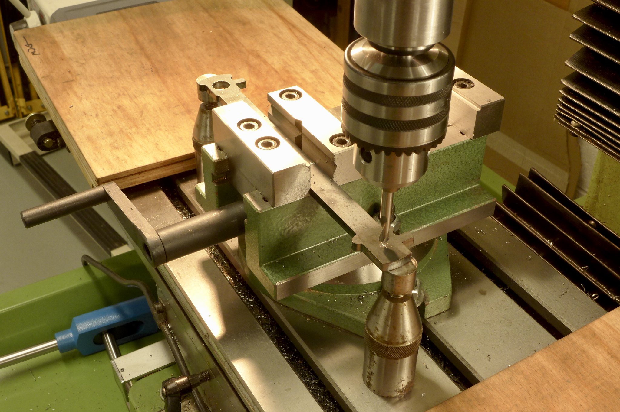 fullsizeoutput_682 fullsizeoutput_682 by Malcolm HARWOOD, on Flickr Cutting the "sausage" slots for the brasses was relatively straightforward. 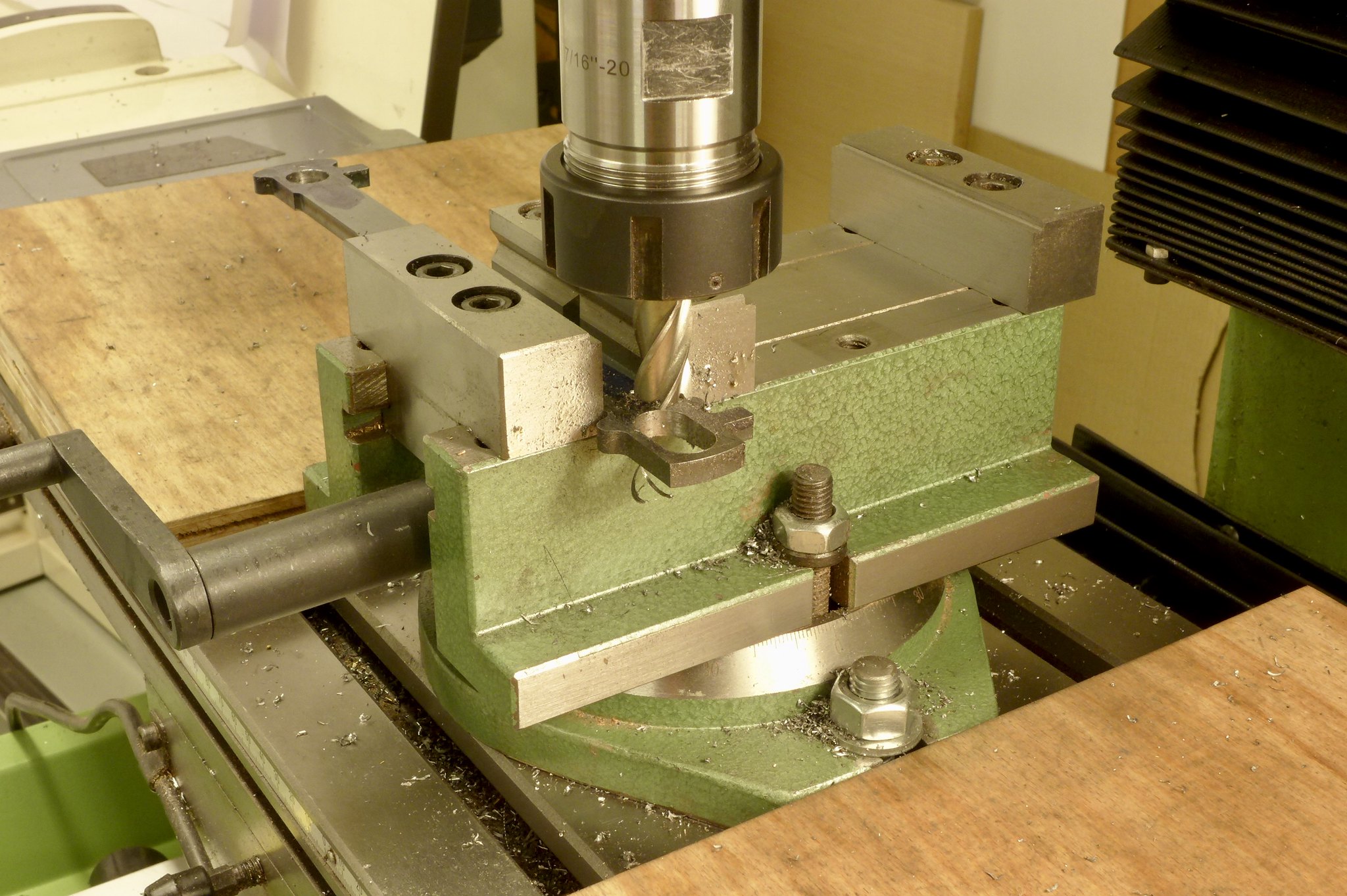 fullsizeoutput_685 fullsizeoutput_685 by Malcolm HARWOOD, on Flickr This was bit of fun. Cutting a 3/32" dia x 1/2" long slot for the cottter pins.The above mentioned hard skin I though might break these small cutters but gentle feeding worked OK. The cotter pins seem to take an age to make, especially fitting them into their slots. Another 2 hour job that suddenly morphs into 2 days! 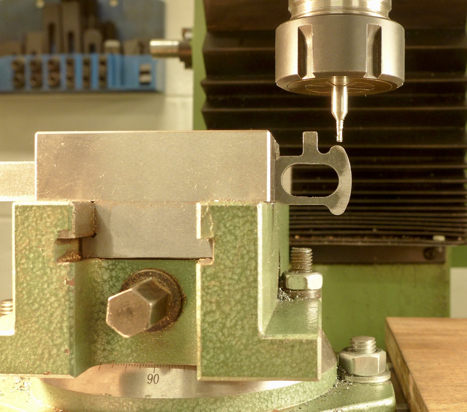 fullsizeoutput_687 fullsizeoutput_687 by Malcolm HARWOOD, on Flickr Next post will be the making of the coupling rod brasses and interpreting Don Young's non scale drawings, plus the difficulty with milling the reverse side of the connecting rods. What's difficult in that I hear you say. Stay tuned and I will explain! Thanks for reading Cheers Malcolm |
|
Lisa
Statesman
 
Posts: 806 
|
Post by Lisa on Feb 3, 2018 23:17:54 GMT
Afternoon Chaps and Chappeses ( are there any female model engine builders by the way?) There's a few of us around, yes. |
|
rrmrd66
Part of the e-furniture

Posts: 339 
|
Post by rrmrd66 on Feb 4, 2018 7:37:36 GMT
Hi Lisa
Great to hear from you.
Hope you are enjoying my first attempt at building a steam locomotive.
Surely though you can not be the only female in 5684 members??
regards
Malcolm
|
|
rrmrd66
Part of the e-furniture

Posts: 339 
|
Post by rrmrd66 on Mar 25, 2018 20:01:03 GMT
Good Evening to you all. There appears to be uncertainty about the derivation of the phrase "the devil is in the detail". However, my suggestion is that is was first used by someone making connecting rod and coupling rod brasses. My last update at the beginning of February 3rd would suggest that I have been slacking and not putting the effort in. This is far from the truth. On average I have spent about 4 hours per day , 6 days per week making these parts. That is about 140 hours. Any way less whingeing and on with the build. So that you don't fall asleep with my ramblings I will split the update into two. First of all THE CONNECTING RODS. I left you last time saying that I would tell you all about machining the connecting rods to thickness. A simple matter of milling 1/16" off each side of the laser cut rods. Here in this picture you will see that I have already made a jig to hold the rod firm whilst milling it. When the first side was finished I turned it over and commenced on the second side only to encounter heavy vibration. This was so bad that I could not get a good finish and manged to blunt the HSS end mill. Packing the under side up with 1/16" plate and clamping it with a heavy duty strap, that you will see behind the rod, allowed me to mill it in "two bites', by moving the clamp as the cutting progressed. Just a note of caution to other beginners, like me. The Don Young design called for 3/8" thick MS bar. The laser cut rods from Model Engineers Laser were delivered in 10mm thick bar. Easy when you know, but had me baffled for quite some time. Maybe the supplier could put on the invoice, or on his web site, that this is so? 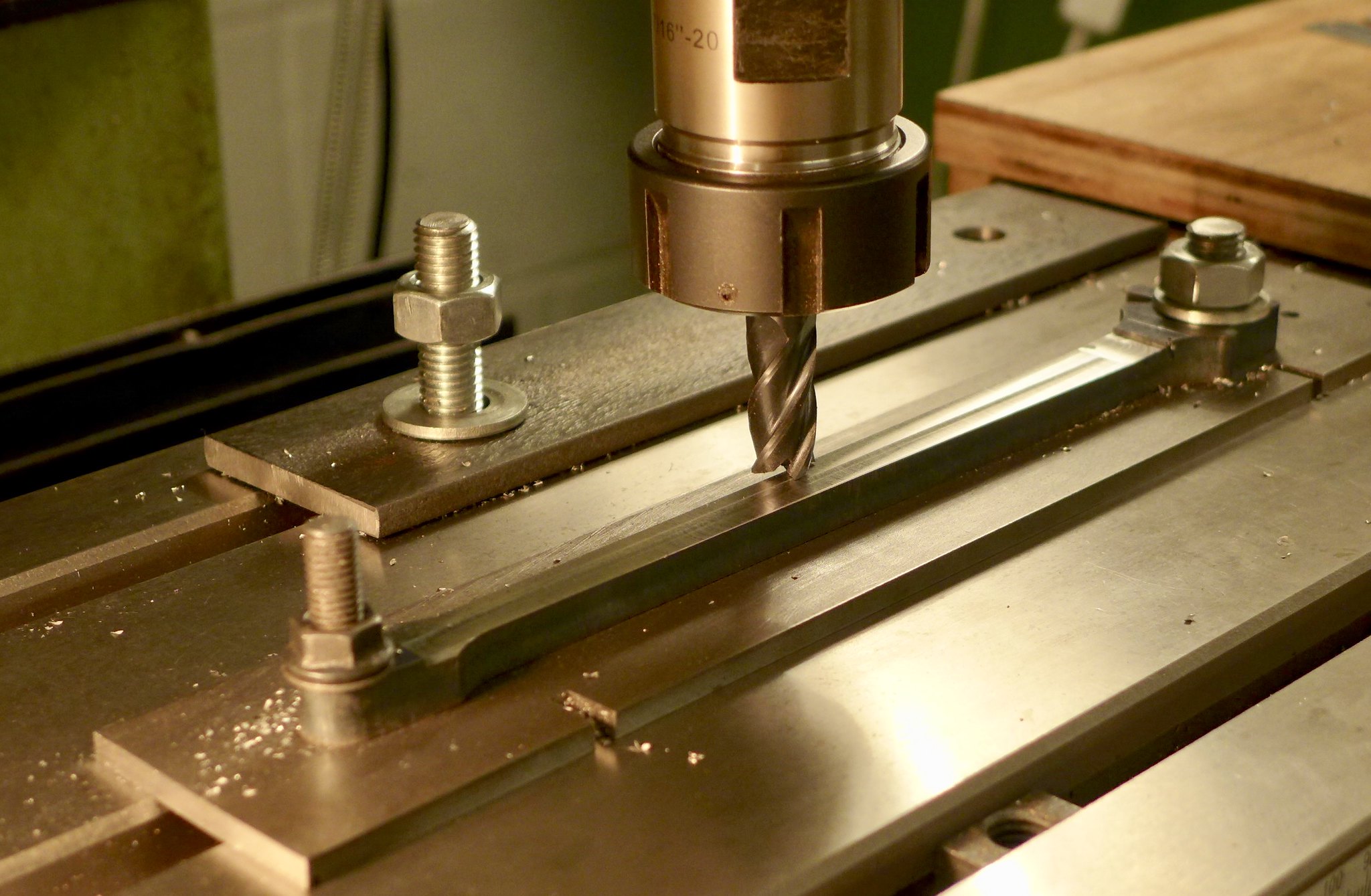 fullsizeoutput_688 fullsizeoutput_688 by Malcolm HARWOOD, on Flickr Next came the brasses. Here you see the milled up blanks, to size, prior to tinning and silver soldering together so that they could be bored as two exact halves. Here again I was dubious as to my ability to be able to do this as silver soldering is a bit of a black art to me, although I must say the more you do it does seem to get easier/better. This picture shows both coupling rod brasses (left hand) and connecting rod brasses (big end) on the right. 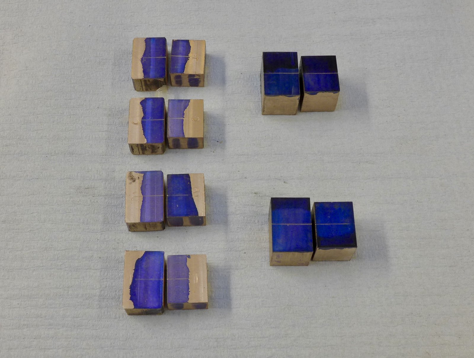 fullsizeoutput_68b fullsizeoutput_68b by Malcolm HARWOOD, on Flickr The "little end" of the connecting rod has one half round bush, the other half being adjustable onto the gudgeon pin in the crosshead by a small sliding wedge and 6BA screw arrangement. (See last picture.) This photo shows the milling of the 15deg. wedge on a nice adjustable angle plate (an extra gift from the friend who gave me his Harrison lathe...thank you Peter) which i set with a digital protractor. You will doubtless recognize the Myford milling vice, which fitted nicely.  fullsizeoutput_68a fullsizeoutput_68a by Malcolm HARWOOD, on Flickr Finally after many hours of hand filing I have them finished. I have everything numbered so that all four rods and their bearings are each a set. 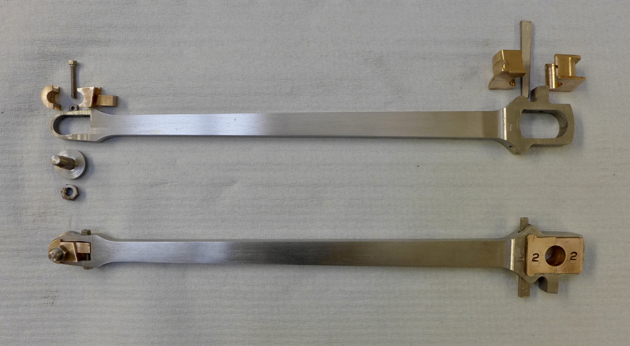 fullsizeoutput_69f fullsizeoutput_69f by Malcolm HARWOOD, on Flickr it only remains for me to prime and paint them. I noticed that all the Hunslets on the Lake Bala Railway, which I visited last October, have painted rods and I will do the same. I will do another post on the coupling rods. Thanks for reading. I do hope this is of interest to a few of you? Cheers Malcolm |
|
|
|
Post by ettingtonliam on Mar 25, 2018 20:37:35 GMT
Nice work Malcolm, but why do you silver solder your bearing halves together? Soft solder is quite adequate for the job, much less heating. In my current project I'm trying superglue, it seems OK so far, and much easier to clean off afterwards.
Richard
|
|
jma1009
Elder Statesman
  
Posts: 5,922
|
Post by jma1009 on Mar 25, 2018 22:25:09 GMT
Hi Malcolm,
Excellent work! Having assembled these type of split 'brasses' on a Hunslet I can appreciate all the work involved, also the coupling rods.
I would agree with Richard that soft soldering the 'brasses' together would be quite adequate, and as you state you 'tinned' then presume 'silver' as opposed to 'soft' soldering is a typo error.
Any news on the cylinders?!
Cheers,
Julian
|
|
rrmrd66
Part of the e-furniture

Posts: 339 
|
Post by rrmrd66 on Mar 26, 2018 7:34:59 GMT
Good Morning Richard and Good Morning Julian
Yes good tip about the soft soldering.In my ignorance I used a small amount of silver solder wire on the fluxed faces, allowed to cool, re-fluxed, then clamped the faces together and reheated until "it looked right"!
The two halves soldered together gave me two matching halves of the 3/8" bore, when they were eventually separated. Worked quite well.
The last time I tinned metal with solder and a soldering iron the size of a house brick was when I found myself doing C&G Metal Work as am apprentice. JFK was still the USA president!
Super glue would have worked I am certain but had none to hand. I find double sided sellotape very helpful as well in this type of application.
Coupling rods write up to follow in next few days,then cross heads and, Julian, the cylinders.
Cheers
Malcolm
|
|
rrmrd66
Part of the e-furniture

Posts: 339 
|
Post by rrmrd66 on Mar 26, 2018 17:25:34 GMT
Evening everybody As promised here is the second half of the con/coupling rod saga. COUPLING RODS The first photo is a repeat of the one posted yesterday in the connecting rod part. However, we are interested this time in the four pairs of PBz pieces in the left hand column. These, Don Young recommends, are to be tinned and soldered together to ensure that after boring to 3/8" diameter they will be "perfect halves" when " broken" apart again. Being new to all this it sounded a bit drastic. However all went well and I was able to proceed to the milling machine.  fullsizeoutput_68b fullsizeoutput_68b by Malcolm HARWOOD, on Flickr The "brasses" are still joined here and are having the locating slots milled. The soldering together also guarantees that the thickness of the slot walls is the same. Note two partly finished brasses stood by the side of the vice. 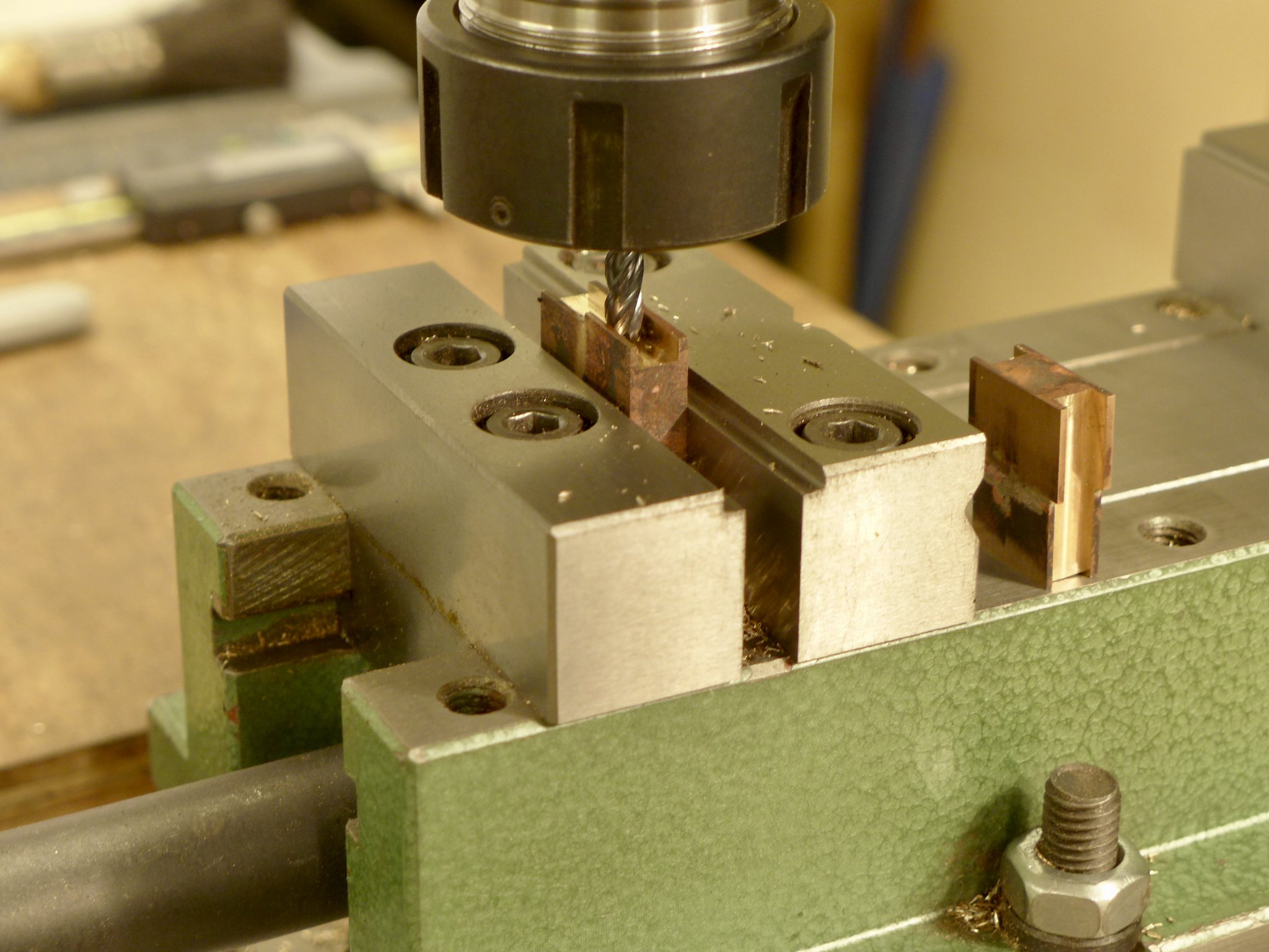 fullsizeoutput_690 fullsizeoutput_690 by Malcolm HARWOOD, on Flickr Next the 3/8" diameter bore was made by slowly opening the hole out ( note drills) and finishing with a hand reamer. Tip here. Make sure that the brass is held as I have shown. If you do it "longitudinally" you may break the soldered joint (like I did on the last one!)  fullsizeoutput_691 fullsizeoutput_691 by Malcolm HARWOOD, on Flickr Here are the bored out brasses awaiting fitting to the coupling rods. If you enjoy hand filing radii in small pieces of Phosphor bronze then you will love the next part. The "back lip", by the way has to be removed otherwise you cannot get the brass into the closed housing in the rod. Each brass has to have one semi circular 1/2" radius,and at the other end a lager radius of about 1.5", or so.  fullsizeoutput_693 fullsizeoutput_693 by Malcolm HARWOOD, on Flickr To ensure that the center distance of the coupling rod is to plan and equal to its partner DY suggested turning up two shouldered pins from scrap axle rod which you will fortuitously have left over after cutting the axles from a standard 12" length. 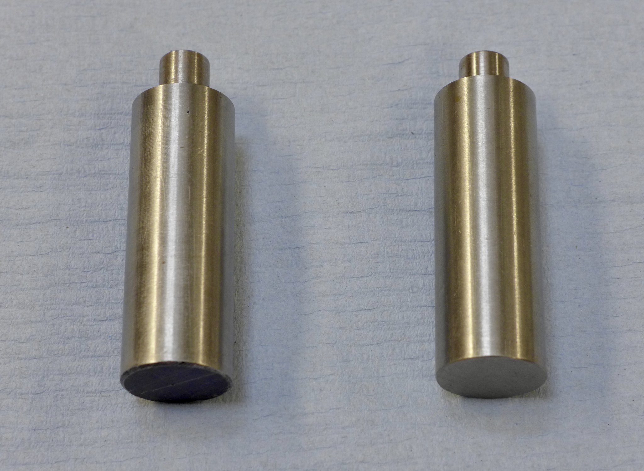 fullsizeoutput_69d fullsizeoutput_69d by Malcolm HARWOOD, on Flickr These are then placed in the horn blocks clamped to their stays. (Please excuse rusty old spare clamps which are very useful in the silver soldering department) Here you can see I have one fitted and am gently coaxing the left hand end to fit. Fortunately, not as difficult as I first thought. 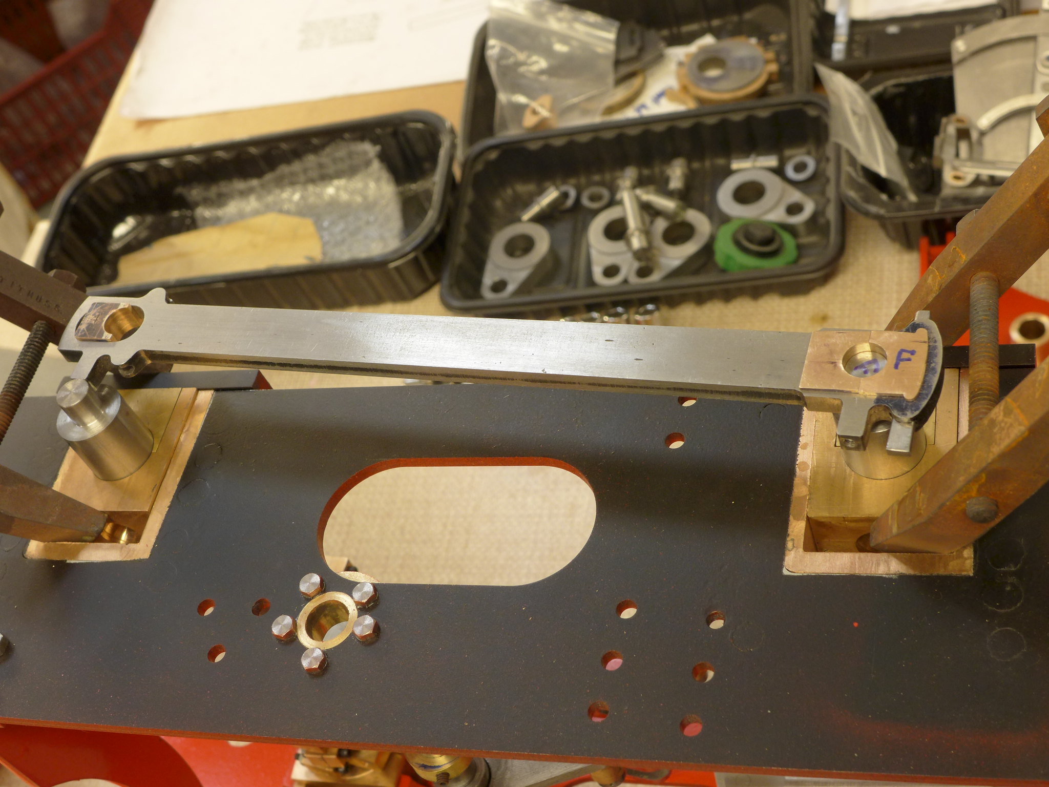 P1010250 P1010250 by Malcolm HARWOOD, on Flickr And here we are. Both finished coupling rods. One assembled and one in "exploded form" complete with cotter pins. 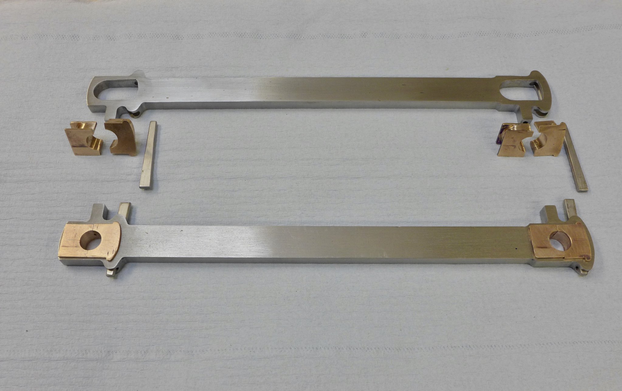 fullsizeoutput_69b fullsizeoutput_69b by Malcolm HARWOOD, on Flickr That's enough for now. Next up are the crosshead fabrications. However I am working inexorably towards the cylinders and valve chests. Yikes! Then the fun will begin. Thanks for reading. Cheers Malcolm |
|
|
|
Post by steamer5 on Mar 26, 2018 20:01:17 GMT
Hi Malcolm,
Great “how to” & lovely work to boot!
Cheers Kerrin
|
|
rrmrd66
Part of the e-furniture

Posts: 339 
|
Post by rrmrd66 on Mar 27, 2018 6:44:19 GMT
Hi Malcolm, Great “how to” & lovely work to boot! Cheers Kerrin Thanks Kerrin. I need all the motivation I can get. regards Malcolm PS Take it easy with our cricketers please. It's bad enough with having the All Balcks! |
|
rrmrd66
Part of the e-furniture

Posts: 339 
|
Post by rrmrd66 on Apr 25, 2018 9:13:56 GMT
Good morning all
Not really an update (boring cylinders at present, pictures and build diary to follow shortly).
One of the forum members (Steamcoal/Hayden) asked if I could edit out the old Photobucket "blocks" and reinstate the original pictures,
Have a look at pages 1 and 2 of this build diary. I think I have done it. It was not as difficult as I feared.
Hayden. I have PM'ed you twice, but you are probably busy sampling this years Sauvignon Blanc vintage!
Cheers
Malcolm
PS A bit concerned about the Flickr/SmugMug news. I hope that we are not going to get the PB saga all over again. It's bad enough for someone like me with just a few photo's on Flickr. I imagine that people like Roger are concerned about their huge collections.
|
|
|
|
Post by Roger on May 3, 2018 6:30:35 GMT
Good morning all Not really an update (boring cylinders at present, pictures and build diary to follow shortly). One of the forum members (Steamcoal/Hayden) asked if I could edit out the old Photobucket "blocks" and reinstate the original pictures, Have a look at pages 1 and 2 of this build diary. I think I have done it. It was not as difficult as I feared. Hayden. I have PM'ed you twice, but you are probably busy sampling this years Sauvignon Blanc vintage! Cheers Malcolm PS A bit concerned about the Flickr/SmugMug news. I hope that we are not going to get the PB saga all over again. It's bad enough for someone like me with just a few photo's on Flickr. I imagine that people like Roger are concerned about their huge collections. Hi Malcolm, I don't think it's reasonable to expect Forum threads to be an everlasting record. I wouldn't be surprised to find that one day it's all gone, let alone the pictures. I do have backups of all the pictures but not the text of course. I'm tempted to write a book when it's all done and dusted which would explore a lot more workshop and CNC stuff. |
|
|
|
Post by Deleted on May 3, 2018 11:27:01 GMT
[/quote]Hi Malcolm,
I don't think it's reasonable to expect Forum threads to be an everlasting record. I wouldn't be surprised to find that one day it's all gone, let alone the pictures. I do have backups of all the pictures but not the text of course. I'm tempted to write a book when it's all done and dusted which would explore a lot more workshop and CNC stuff.
[/quote]
Hi guys....this has been something that's been on my mind of late, my son (computer man) has been on my case (a lot) suggesting that I start my own 'blog', he can support it on one of his own servers. I'm not so sure, I already post updates on 3 sites which takes time although most is straight forward copy/paste. A blog though would need much more input, or it would IMHO, more like a book than a forum post and then what do I do about my current build threads? decisions, decisions...lol
Pete
|
|
|
|
Post by joanlluch on May 3, 2018 13:37:27 GMT
Hi guys....this has been something that's been on my mind of late, my son (computer man) has been on my case (a lot) suggesting that I start my own 'blog', he can support it on one of his own servers. I'm not so sure, I already post updates on 3 sites which takes time although most is straight forward copy/paste. A blog though would need much more input, or it would IMHO, more like a book than a forum post and then what do I do about my current build threads? decisions, decisions...lol Pete With your own blog you have full control of users and posts. Unlike a forum, a blog allows you to filter what's posted and manage who is allowed to post. The next level is a content management system (CMS) such as WordPress and Joomla. I would definitely chose them over a blog because they offer all the features of a blog plus a lot more. These CMS started as blogs, so they are still very blog oriented. When I entered the hobby I immediately created a WordPress site to record my progress lsfornells.com. (Although I currently have it essentially abandoned). You can keep a CMS site on your own physical server (for free) or pay a very reasonable fee to have it on their own servers. They are also fully integrated with internet search engines such as google, so everything you post there is globally searchable. On the paper they have all the advantages, they are great to keep a long term record of your build which hopefully will last as long as web technology isn't supplanted by something better. On the other hand, internet forums are designed to meet people alike with your interests, and that's their main strength. You don't have control over forums because you are just logging in as a member of a community. Depending on each own priorities a forum or a blog (CMS) can be chosen. I suppose some people keep using both to have the best of both worlds. A CMS can even have its own forum btw. Joan [pd. This is off-topic, so I suppose this is a case where the last recent posts can be moved to a separated thread by a moderator as suggested elsewhere (?)] |
|
|
|
Post by springcrocus on May 3, 2018 22:39:08 GMT
I've only just caught up with your build log, Malcolm, and there is some excellent work on display here and much to be learnt from. I thoroughly enjoy following your construction.
Regards, Steve
|
|
rrmrd66
Part of the e-furniture

Posts: 339 
|
Post by rrmrd66 on May 4, 2018 6:36:20 GMT
I've only just caught up with your build log, Malcolm, and there is some excellent work on display here and much to be learnt from. I thoroughly enjoy following your construction. Regards, Steve Hi Steve Thanks very much. I am very happy you are finding it interesting. I have just completed my first year as a virgin builder and have learned so much. Update soon on between centres boring bars and boring the cylinders. Cheers Malcolm |
|
rrmrd66
Part of the e-furniture

Posts: 339 
|
Post by rrmrd66 on May 16, 2018 20:28:22 GMT
Evening everybody.
Cylinders Part 1.
Lots to catch up with here.
The cost of the PBz "cylinder set (20 pieces) is an eye watering £500+. Thus, as that well known philosopher Sir Alex Ferguson, once famously said this is " squeaky bum time" (Incidentally, happy to hear he is on the mend)
I had decided that as I have a Myford vertical milling attachment (VMT) that I would make a between centres boring bar and mill the bores horizontally. The making of the bar ( I made two of them) was posted in tools and tooling section the other day, if you are interested.
First of all I wanted to mill the flat faces on the back of the cylinders before boring them. I wanted the castings to sit on the milling machine as close to the central axis of the casting as possible. Thus I made a dummy shaft so that I could mount the casting on the miller and create the reference faces on the cylinder back.
This is a piece of 1.5" MS bar machined down on the recently acquired Harrison M300 to be a snug fit.
The Lathe is a bit like me some days. Old and tired!
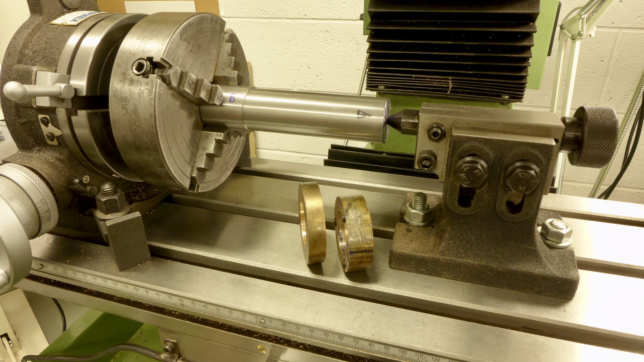
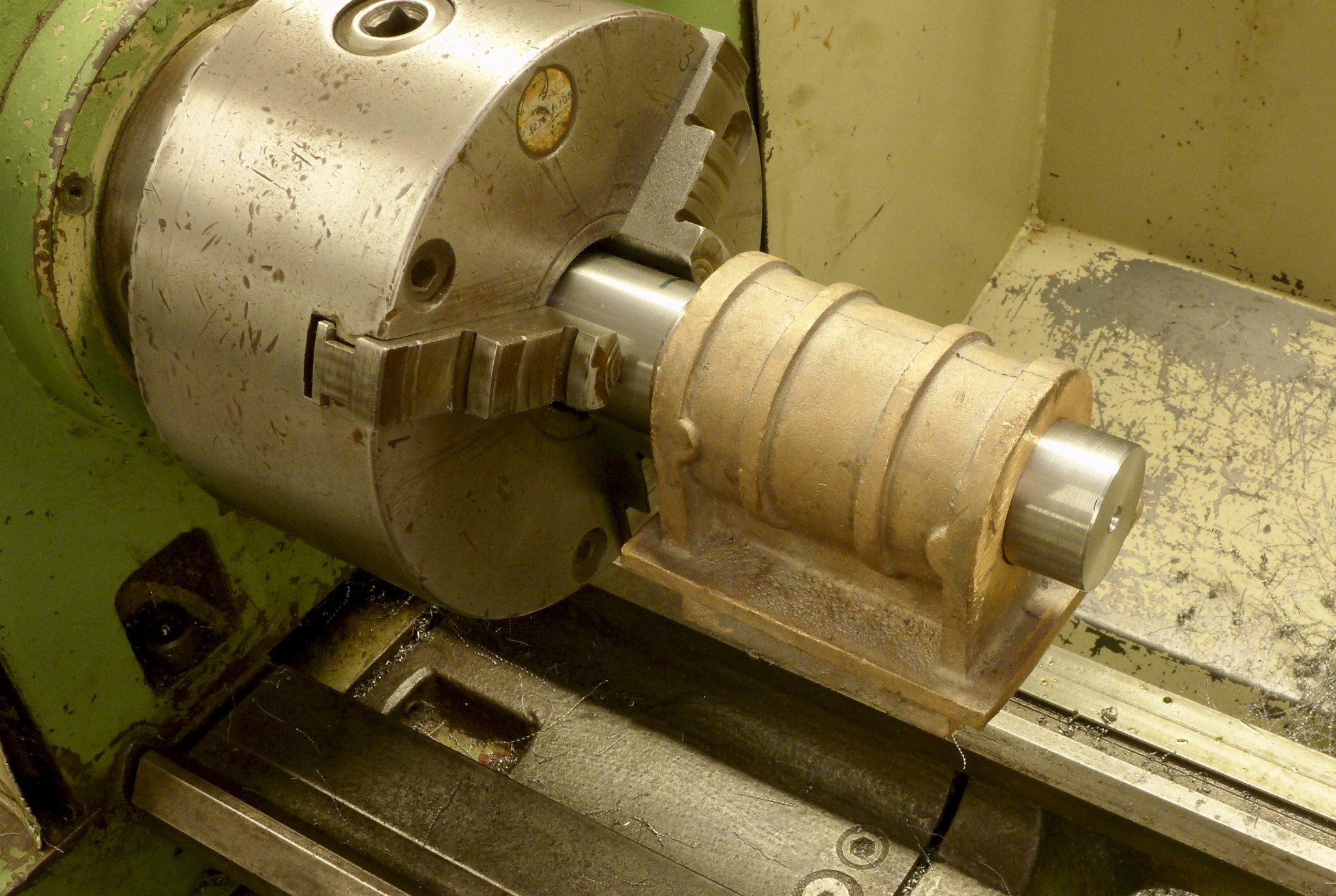 fullsizeoutput_6a4 fullsizeoutput_6a4 by Malcolm HARWOOD, on Flickr This shows the bar mounted in the mill in the rotary table with the centre so that I could get the set up as rigid as possible. The rotary table allowed me to get the reference surface truly horizontal.
The casting locates against the small shoulder on the left of the bar and is axially constrained by the pressure pad and thrust ring which contains 3xM8 dog point Allen screws. The thrust ring itself is attached to the dummy bar by 3xM5 screws..
 fullsizeoutput_6a5 fullsizeoutput_6a5 by Malcolm HARWOOD, on Flickr So here we are generating the flat surface and sides for the bolting flange that will attach the cylinder to the engine frames.
You will be glad to see that the set of toolmakers jacks I made sometime in the 16th Century are being pressed into use. And very useful they have turned out to be,
Next the steam port face is generated with the fly cutter. This tool was new to me and I lay awake at night worrying will lit work or not? Yes it did and gave a really nice finish.
This Don Young designed Hunslet has balanced slide valves and only needs the two ports as shown. The large central exhaust port is omitted. Here I am chain drilling the ports to start them off.
All done. Some look a bit off centre line. However they will tidy up in a moment.
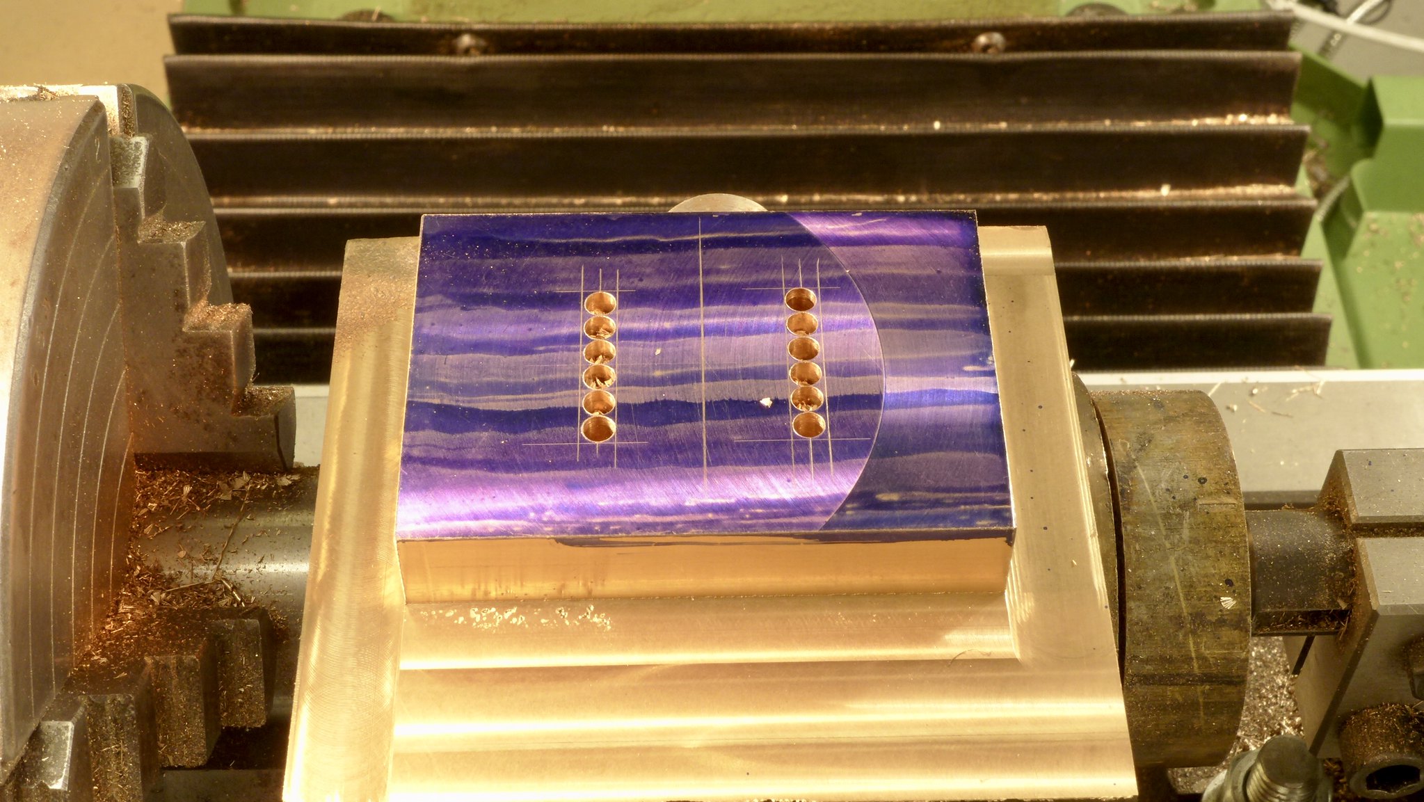 fullsizeoutput_6ab fullsizeoutput_6ab by Malcolm HARWOOD, on Flickr Milling the ports out to the required dimension
Upon completion of this process I then had to think about boring the cylinders to 1.625" dia.
I knew that the rear surfaces were to drawing but could not be certain where the casting axis was in relation to the drawing axis. I made a hard wood plug (maple, if you want to know) and marked of the actual center line on the surface plate with the vernier height gauge. The centre pop in the wood is from the lathe. The cross lines are from the two reference points (vertical and horizontal) and to drawing. The scribed circle is to give me a rough idea of how much I have to remove. 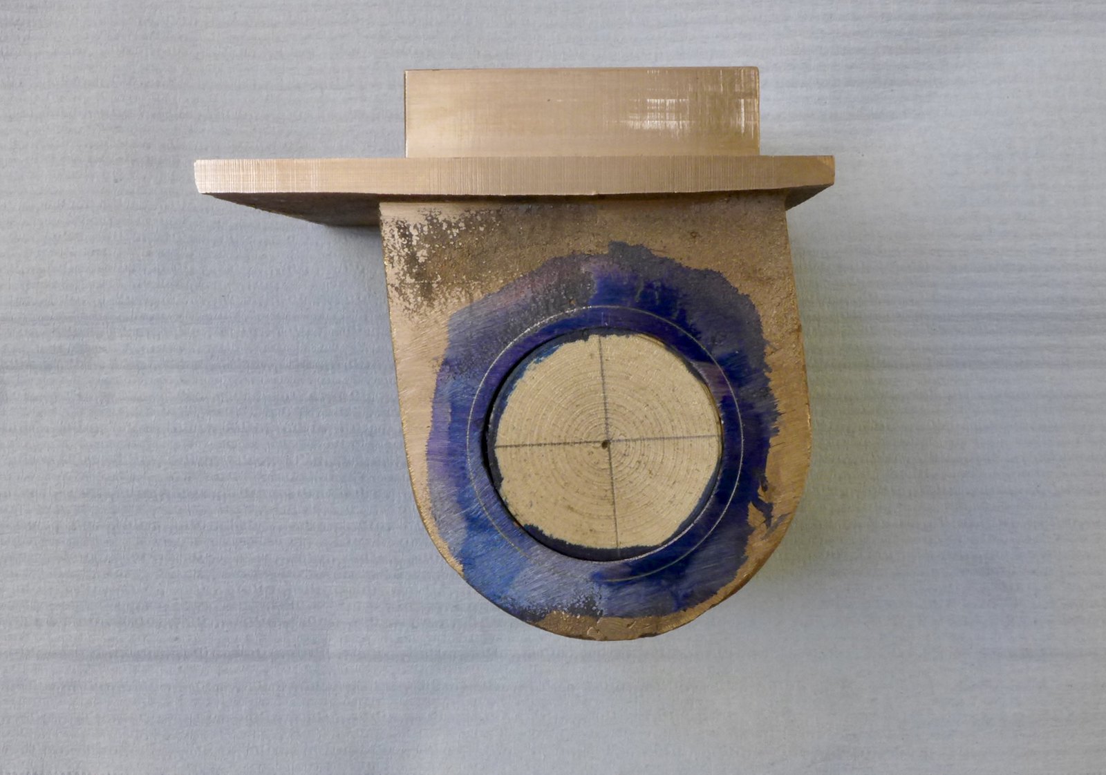 fullsizeoutput_6ac fullsizeoutput_6ac by Malcolm HARWOOD, on Flickr
This is the set up in the VMT on the Myford. i made some MS straps with which to tie it all down to the tee slots on the VMT. The wooden plug enabled me to line up, by eye the centre of the casting in the Y and Z axes, using hte lathe centre.
Somewhere in the back of my mind I saw a fancy plug to keep the swarf out of the hole that results when removing the compound slide from the lathe. No matter, must have been a dream. I will use a piece of wiper paper.
Two days later I discovered the plug still in its original Myford bag, unopened . Grrrr!
I have decided I don't like the VMT. It t is not really up to job even though I was taking very light cuts (see my post in tools and tooling about tool advance system).
In an attempt to reduce movement I resorted to the strange set up as seen below. However when boring the second cylinder, which was out of round, the interrupted initial cuts caused the cylinder to rotate about its one nut and cause a dig in and a mild heart attack. The cantilevered design of the VMT is not good. I should have used an angle plate but the standard Myford one is too small and my others are almost as big as the Myford itself.
Here are the two boring bars. One for "roughing out", until about 0.020" from finished size, then the "finish size" that was kept over from the last cut of cylinder No. 1. Hence the tape. I should end up wit two identical diameter cylinders. 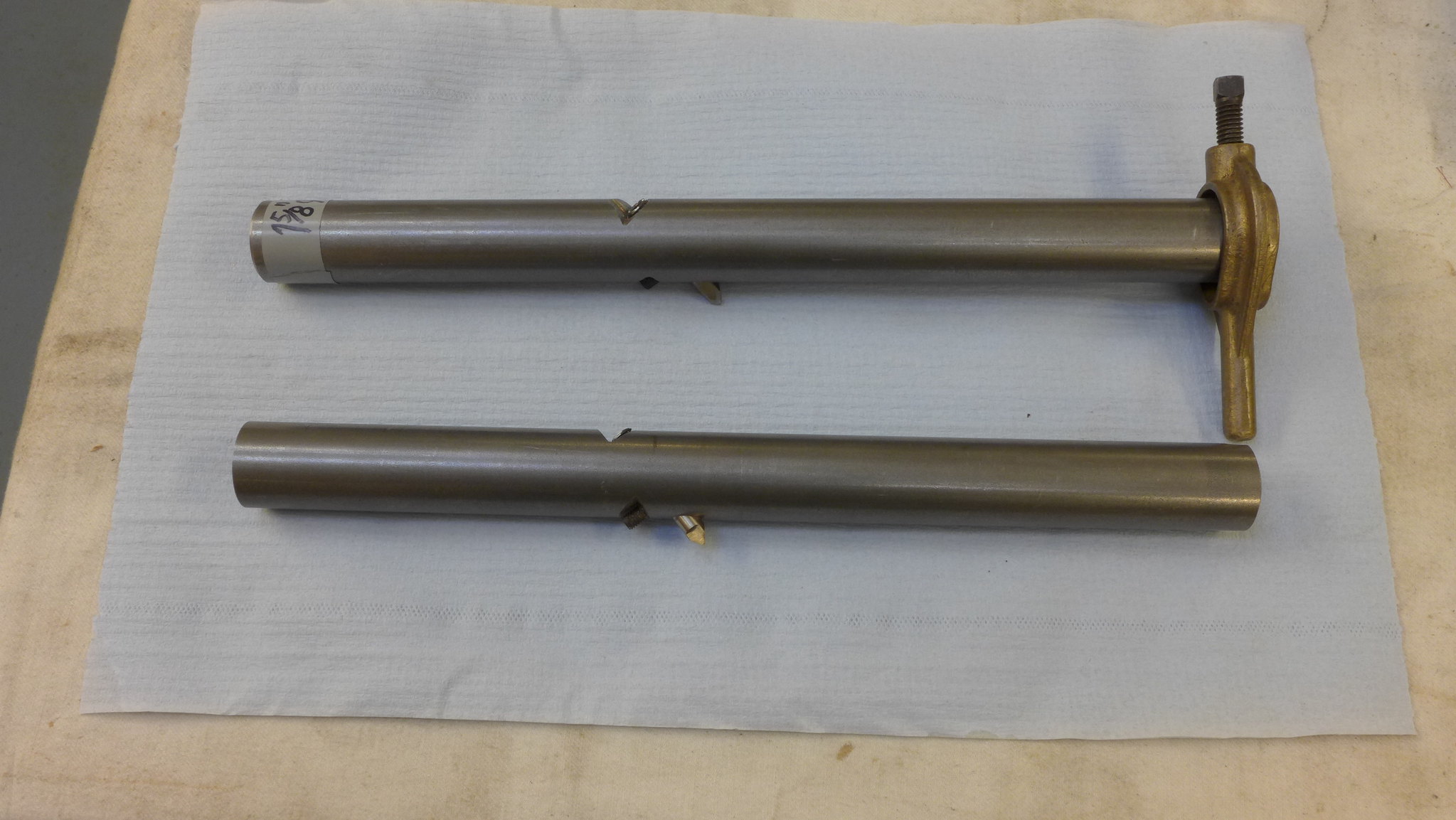 P1010277 P1010277 by Malcolm HARWOOD, on Flickr
Following the minor heart attack I reinforced the fixture to minimise any likelihood of the VMT turning about its rear mounted fixing bolt.
Finally here is a finished cylinder, about 0.001" under size, as I intend to run a hone in the cylinder to give it some "lubrication cross hatching"
In the next part I will report on how I generated the "gland face" to the cylinder so that it was normal to the axis of the piston rod.
Hope you found this interesting and didn't fall asleep whilst reading it?
Cheers
Malcolm
|
|