Good Evening all.
A few weeks have gone by since my last update. Lots to show, so lets get on.
CYLINDERS PART 2
I finished my last posting with the promise that I would show how, following in between centres boring of the cylinders, I attempted to face the cylinder end faces square with the bores.
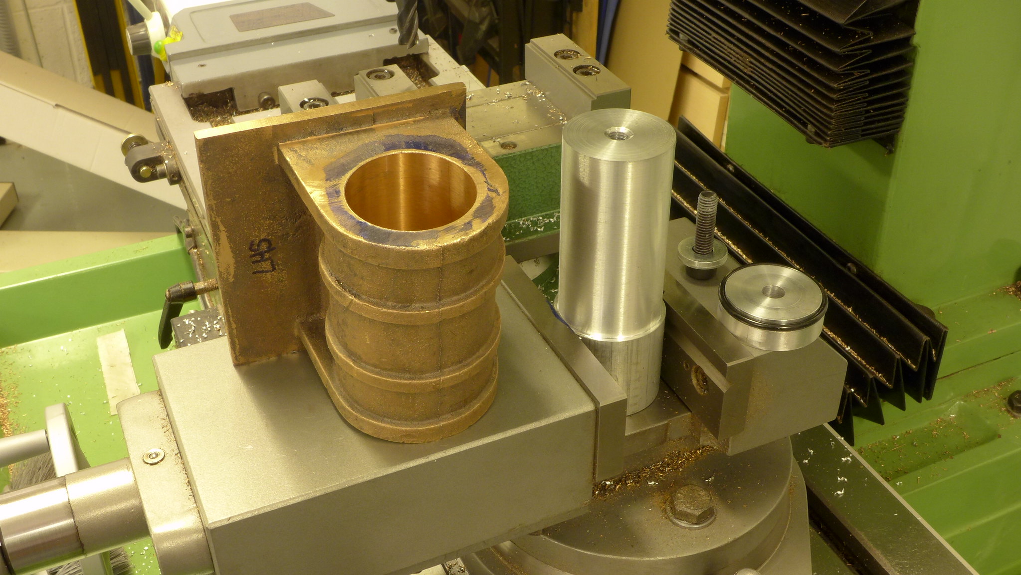
Here is the tool I turned up from 1.75" Al. bar to 1.625" dia. This was clocked in the milling vice in all directions and clamped up. The cap, secured by a socket head cap screw, compresses the O ring sufficiently to expand radially and clamp the cylinder casting to the aluminum shaft (or so I hoped).
 P1010285
 by
Malcolm HARWOOD, on Flickr
The finished height of the cap was below the end of the casting so that I could run the end mill across the face.
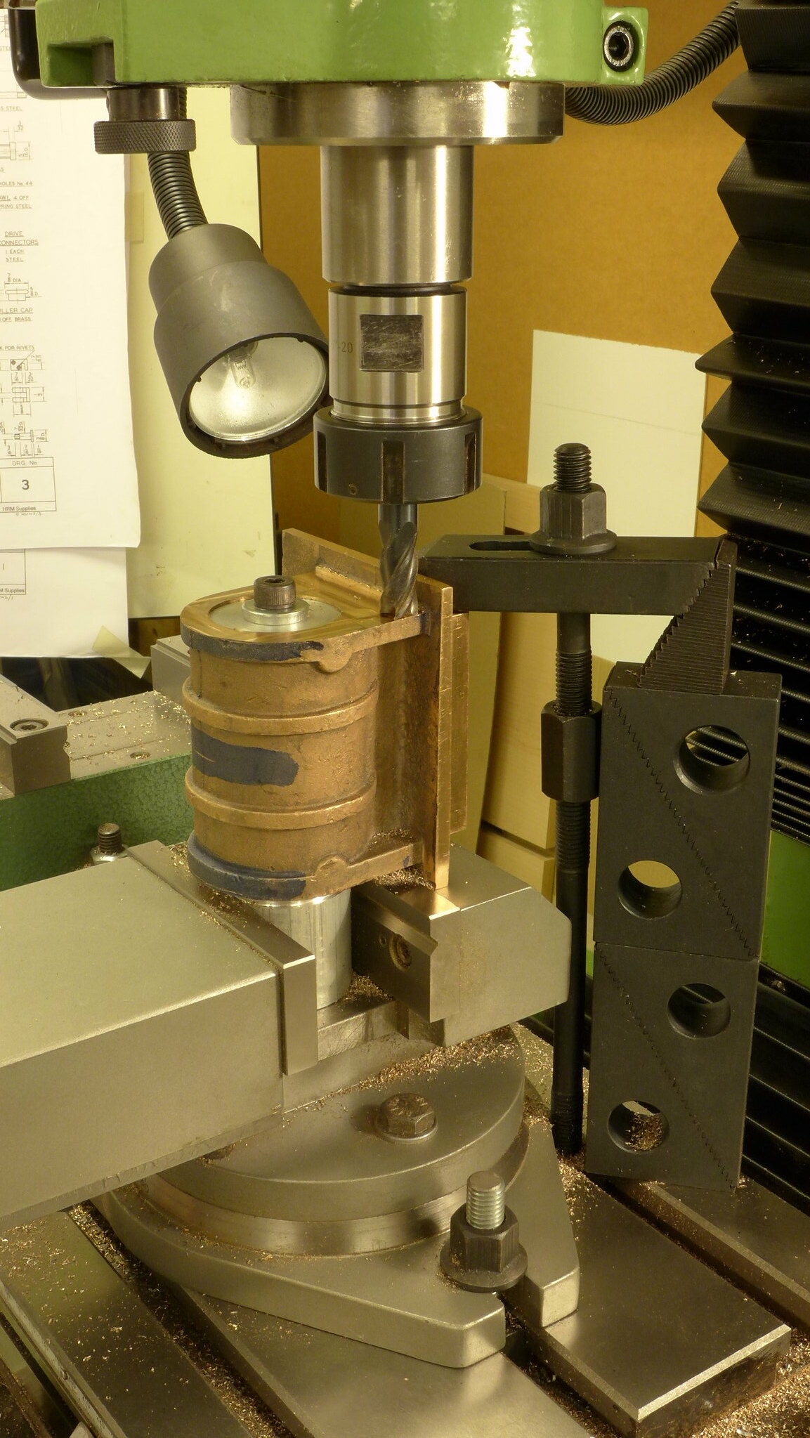
Pride cometh before a fall, as they say and the milling forces were sufficient to overcome the O ring clamp and spin the casting on the shaft ( or at least try to)!
I thus resorted to a more positive clamping arrangement.
 P1010286
 by
Malcolm HARWOOD, on Flickr
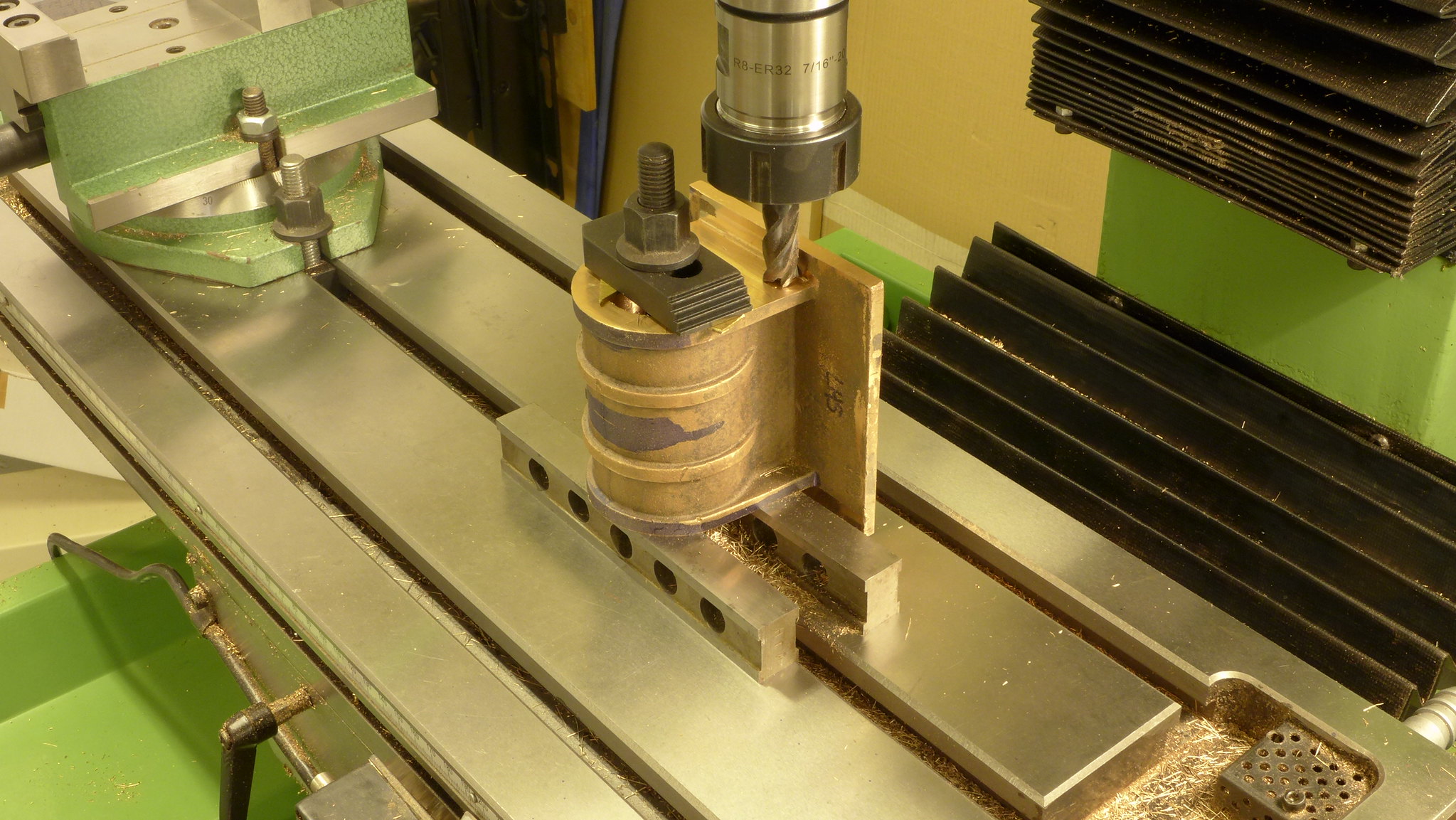
Following establishing one face normal to the axis of the bore I was able to flip the casting over and mill square and to length.
( Oh no! It's those pesky apprentice made parallels again  )
)
 P1010287
 by
Malcolm HARWOOD, on Flickr
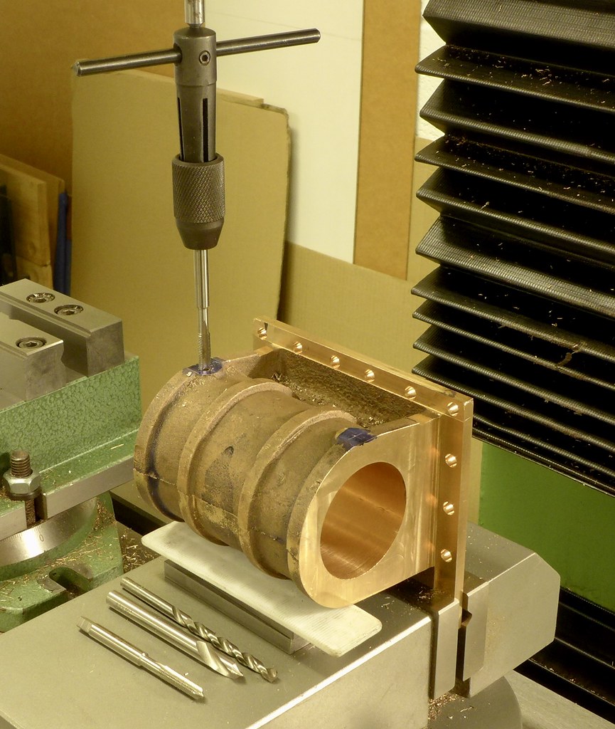
At some point, if you are following this thread and making your own Hunslet remember that the cylinder drain cock threaded holes have to put in and that when you come to drill the cylinder end faces there is a potential problem about to occur.
Note the white plastic spacer, much beloved by window and kitchen fitters. They come in varying thicknesses and colours and are a real time saver, even if not quite ME standard!
 fullsizeoutput_6e5
 by
Malcolm HARWOOD, on Flickr
Don Young's words and music covers construction of both 5" and 7.25" gauge loco's.
The 7.25", called John Hunslet (the 5" is named Don Hunslet ) has a 7/32"ME thread in its outer end cap and he advises doing so for the 5" version. Although it means that you have to make a couple of 7/32"ME threaded plugs it does allow you to use the riser on the casting as a chucking spigot.
A dummy mandrel, with the 7/32"ME thread can then be used to turn the inside face with mounting spigot as well as the OD.
This chucking spigot can be used in the three jaw chuck on the rotary table to drill the 11 mounting hokes in the cylinder end cap prior to removal.
I subsequently made two 7/32"ME plugs from hex brass bar incorporating space for a fibre washer.
At this point you will note that there are 11 holes, not equipspaced due to offsets to enable the steam passages from the ends of the cylinders into the steam chest.
DY suggested that one of the holes were to be at 6 o'clock but this coincides with the previously mentioned drain cock tappings.
Solution is to move this hole slightly to the left, about 7°. Look I have even got the Tan tables and the old Zeus chart out to confirm.
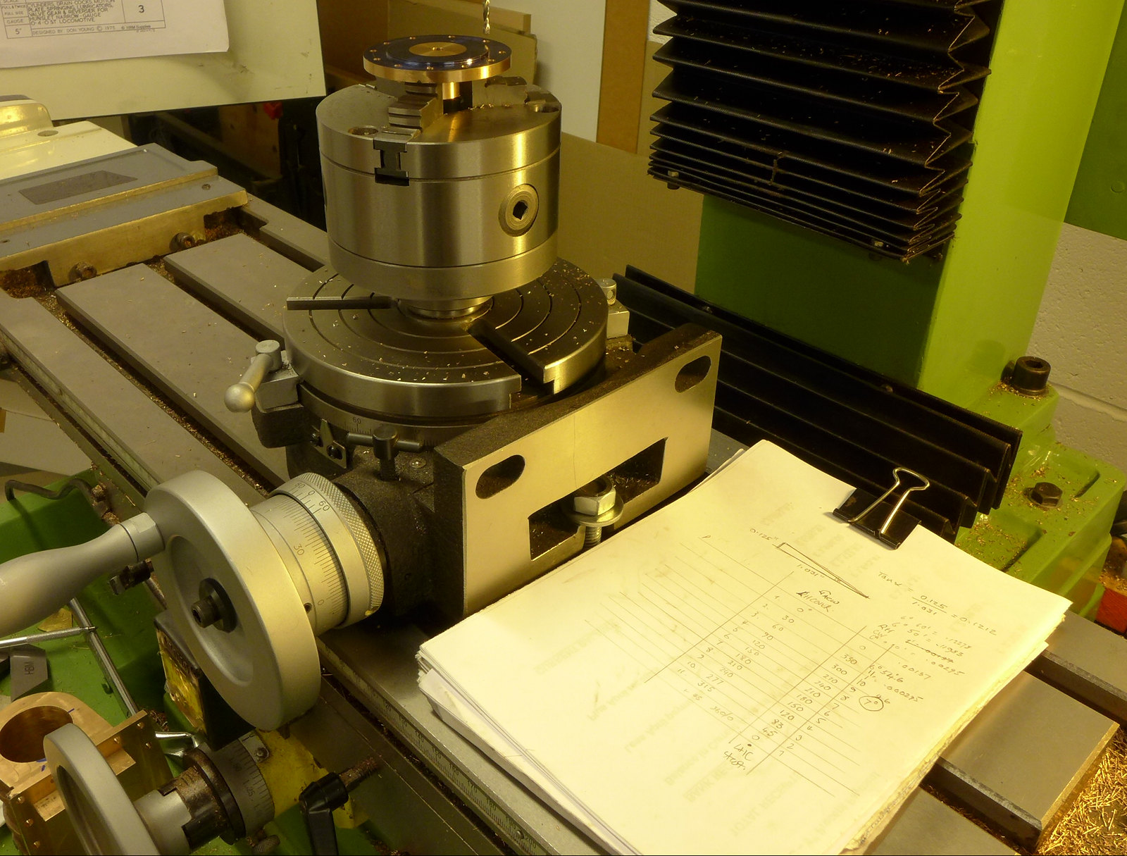 P1010295
 by
Malcolm HARWOOD, on Flickr
Next, it was meant to be all down hill from there on.
Oh no it wasn't.
Question. If a man drills and taps 11 6BA tapped holes which number hole does he break the tip of the tap in?
Answer: No.11, of course.
What to do next ,is then the question.
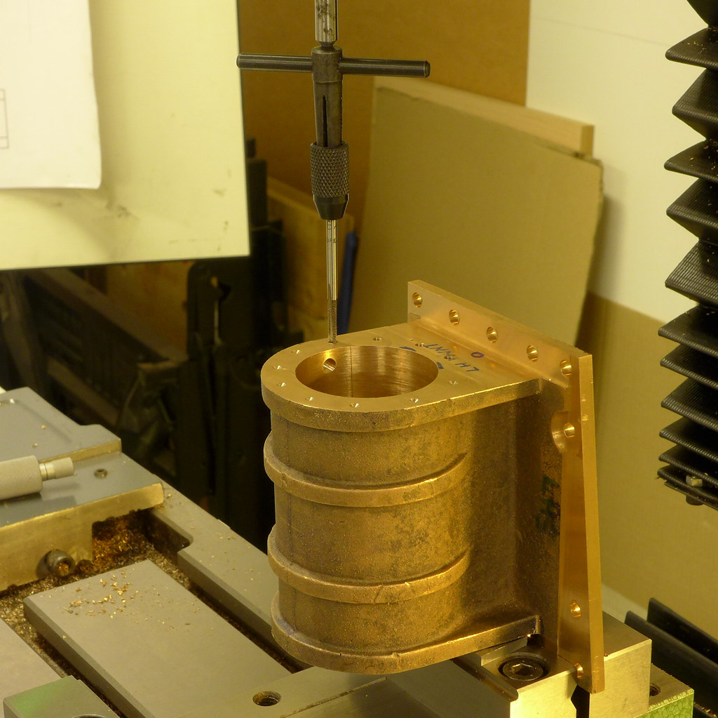 P1010299
 by
Malcolm HARWOOD, on Flickr
After failing to mechanically extract the tip of the tap I resorted to a bit of electro-chemical trickery.
I have often read about dissolving ferrous metals in non ferrous castings with an Alum solution
The internet suggested that this was not always successful although one guy in New York knew how to do it correctly.
First you should use Alum (Aluminum Potassium Sulphate) from a chemist and not the domestic dye fixer type.
Make a saturated solution. (The point at which the crystals will dissolve no further) in very hot water. Just simmering.
You will need at least 250grammes to 250ml of water. Possibly more.
Immerse the casting in the solution and keep the temperature just below boiling. You should see, almost immediately. a stream of bubbles emanating from the broken tap.
Leave cooking, 5 hours in my case,until the bubbles stop and the tap will have disappeared. Magic.
Here is my Master Chef set up.
After that little episode it was back to turning the cylinder gland end cover.
Don Young obviously had a sense of humour because it takes about a day looking for a detail drawing of the gland follower to find only a small note to say that they are the same as the gland follower in the eccentric driven boiler water feed pump.
So where are the castings in the expensive Reeves "package deal complete casting set"? Nowhere! Shall I make them from solid bar with most of the bar being swarf of buy two more castings from Reeves, pointing out that they could, to their benefit, include them in the set and charge accordingly? This suggestion was received with what I would politely call '"indifference". Always a pleasure to spend money with enthusiastic suppliers.
Yes, sharped eyed readers will notice a spacer disc at the back of the flange. This was to throw the surface about to be machined clear of the chuck jaws.
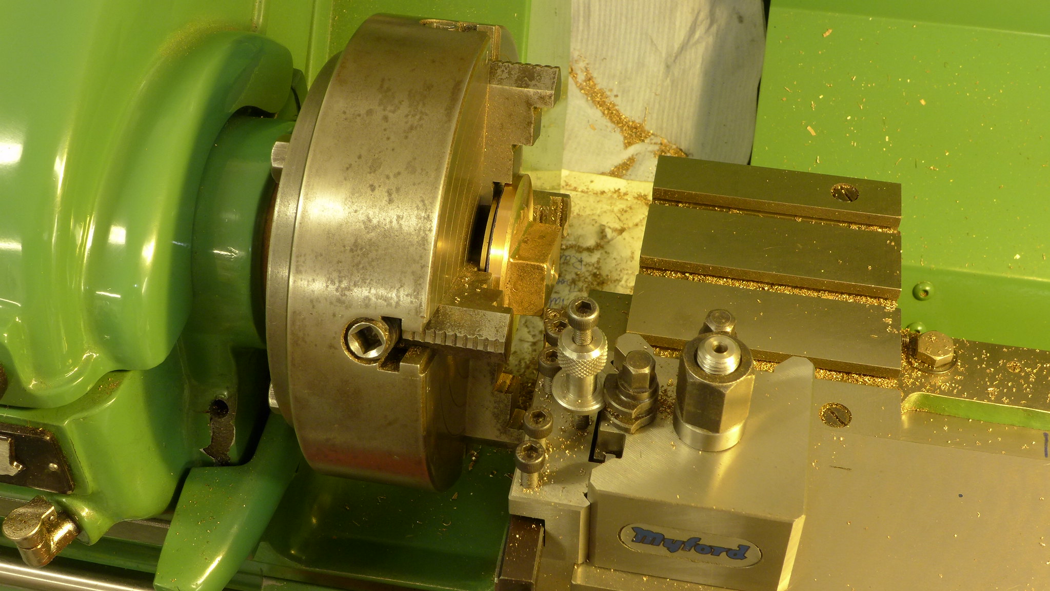 P1010296
 by
Malcolm HARWOOD, on Flickr
There was recently a discussion about the use of the compound slide on the lathe. I started boring the gland on the with a very thin and ancient HSS tool that would allow me to turn the bore and also internally face it of square by judicious use of the compound slide, forgetting that I had not clocked it to the lathe axis and ended up with a tapered bore. Very naughty.
I discovered my mistake when about 10 thou over and managed to rectify it with a proper boring bar on the next gland. Result is to have two dissimilar gland followers that are not interchangeable. Not the end of the world, but annoying.
Next up was drilling/milling the steam passages from the ends of the cylinders to break into the slots in the back of the steam chest.
This is not easy and after a fruitless attempt to determine the angle in CAD (Oh! The shame) I did a full size drawing and reckoned it was a tad over 40° to the horizontal so set up my trusty tilting table and plunged in.
The problem here is the steam passage is about 1.25"-1.5"long x 3/16" dia and long slot mills are not readily available.
Many thanks to the 4 fellow members of the forum who made various helpful suggestions ( You know who you are!).
In the end a combination of needle files and rotary burrs on the Dremel with a flexible shaft won the day.
This shot shows the vertical set up of the casting at 40° with a set square lined up with the centre of the steam a passageway in the back of the steam chest.
So that is about it for today. I am now on with the piston heads and rings upon which I will report back shortly.
Thanks for staying with me this long I hope you have found it interesting and maybe even a little educational?
Cheers
Malcolm.