|
|
Post by Jim on Jan 23, 2018 20:46:41 GMT
You're doing a great job there Mike.
Don't worry about age I'm 79 this year and banging on regardless, not sure of what but I am. Like you and Pete I started from scratch and acquired skills as I went along, just as you do in life. Like the song says, you do it your way.
Keep up the great work.
Jim.
|
|
barlowworks
Statesman
  Now finished my other projects, Britannia here I come
Posts: 878 
|
Post by barlowworks on Mar 4, 2018 13:37:07 GMT
Hi everybody Time for a bit more skulduggery from Barlow Works. I'm still on with detailing the tender and this is a photo of what we started out with. I recently showed detailing the horn guides and this is now showing work to make the springs and hangers look a bit more like the real thing. 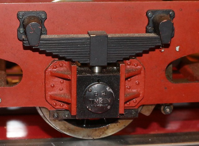 Img_1314 crop Img_1314 crop by Michael Cawthorne, on Flickr Firstly, I modified the spring hangers. I know I could have got some of Adam's beautiful castings but all this already exists and the holes have been drilled so it is a case of making it look a bit better . I milled out a groove in the top to take a piece of channel and soldered them in place, then profiled the channel with a carbide disk in my mini drill. I also cut a groove in the bottom to take a plate to secure the plates for the spring safety hooks and pads to be fitted later. 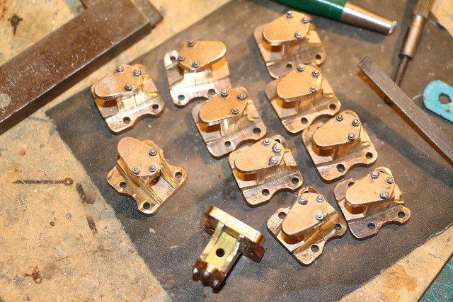 IMG_2107 IMG_2107 by Michael Cawthorne, on Flickr Here is a trial fit with the plates. 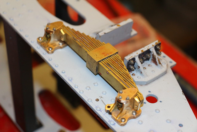 IMG_2110 IMG_2110 by Michael Cawthorne, on Flickr The springs were originally fitted with cheesehead screws so I made up some custom screws to look like bolts. 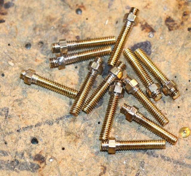 Img_2113 crop Img_2113 crop by Michael Cawthorne, on Flickr I also milled up some spring bearing plates for the top of the horn guides. 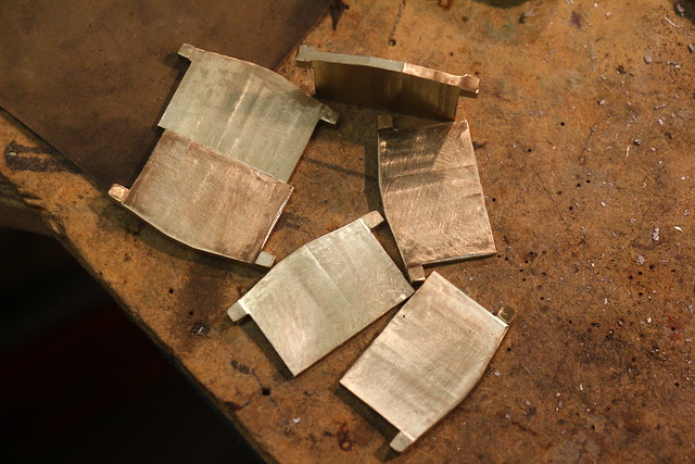 IMG_2120 IMG_2120 by Michael Cawthorne, on Flickr This is a picture taken of Oliver Cromwell showing some of the parts I am modifying. 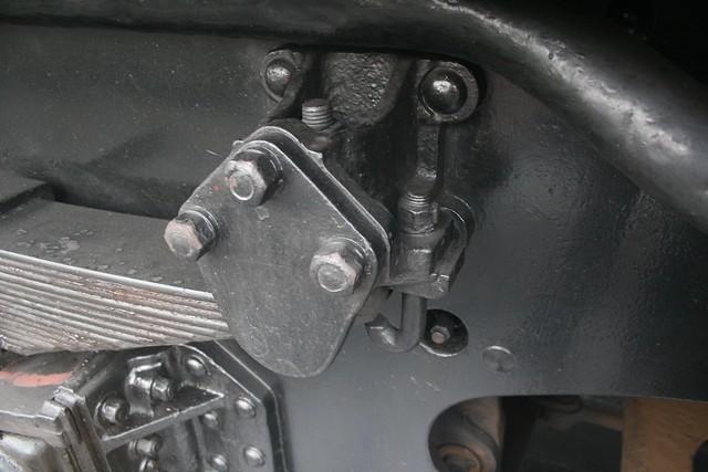 img_6356 img_6356 by Michael Cawthorne, on Flickr And finally this is what they look like now. I put a small 10ba nut and bolt in the spring bearing plate to represent the grease nipple. The springing is done by a piston with a spring in it going down the centre of the fabricated spring. The bearing plate now has a hole in it that this piston comes through to bear on the axle box. You can also see the safety hooks on the ends of the springs.  IMG_2123 IMG_2123 by Michael Cawthorne, on Flickr Again, it's just detailing to make it look like the real thing. Next up is modifying the axle boxes like Don did on his 9F rebuild. Until next time. Regards Mike |
|
don9f
Statesman
  Les Warnett 9F, Martin Evans “Jinty”, a part built “Austin 7” and now a part built Springbok B1.
Posts: 961 
|
Post by don9f on Mar 4, 2018 18:08:07 GMT
Hi Mike, I’ve just read through your thread again from the start....great work and the improvements to the tender axleboxes will be the making of it!
Don’t know how the designers got the dimensions of the boxes and the Timken covers so wrong?
Look forward to seeing more.
Cheers Don
|
|
barlowworks
Statesman
  Now finished my other projects, Britannia here I come
Posts: 878 
|
Post by barlowworks on Mar 4, 2018 20:22:04 GMT
Hi Don, I know what you mean. The Timken covers on my axle boxes were bigger than the turning on the face, plus, off the 6 I think I had 2 that were the same. I'm looking forward to doing the axle boxes and have some covers from Adam to fit. I'm really enjoying doing the detailing, I think it will make the model and it helps to get me a bit of experience in working with metal.
Mike
|
|
|
|
Post by Jim on Mar 5, 2018 1:20:46 GMT
Looking at the great work you're doing Mike I'd have to say I think in terms of getting experience in working with metal you're already up there with the best. I know there are all sorts of little tips and tricks we can pick up, that's why I'm always snooping around locos in the steaming bay    Jim. |
|
barlowworks
Statesman
  Now finished my other projects, Britannia here I come
Posts: 878 
|
Post by barlowworks on Mar 16, 2018 17:02:56 GMT
Hi Everybody More shenanigans from Barlow Works. The next thing on the tender detailing were the axle boxes. This is what they should look like, taken from Britannia's tender. Unfortunately, Don in his 9F build beat me to the punch with these but I always intended to do it as I think they set the tender off well.  img_0226 img_0226 by Michael Cawthorne, on Flickr This is how they came on the tender, built as per drawing. If you look closely you will see that the axle box covers are all different and some of the retaining nuts had fallen out. The others were removed without much difficulty. 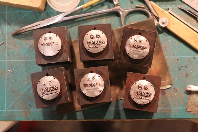 IMG_1360 IMG_1360 by Michael Cawthorne, on Flickr I turned off the old covers which were attached with Araldite and the axle boxes had a quick blast in the grit blaster to remove all the old paint. 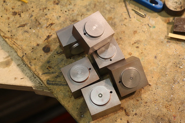 IMG_2121 IMG_2121 by Michael Cawthorne, on Flickr As the outer bosses for the axle box covers were too small I turned them down to 10mm and used them to locate a piece of brass bar with a 10mm hole in to aid soldering. The original axle boxes were flush with the outside of the horn guides but as can be seen from the photograph the axle box stands proud from the horn guide. The brass bar was just over 6mm which was just right. This meant that I would loose the oiling points but as the axles run in ball races and I intend to pack them with grease when I reassemble them. 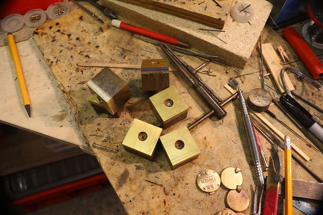 IMG_2127 IMG_2127 by Michael Cawthorne, on Flickr The axle boxes were then put into the mill and milled flush on the sides. Then into my dividing head to be milled to the correct profile with a ball nosed cutter. 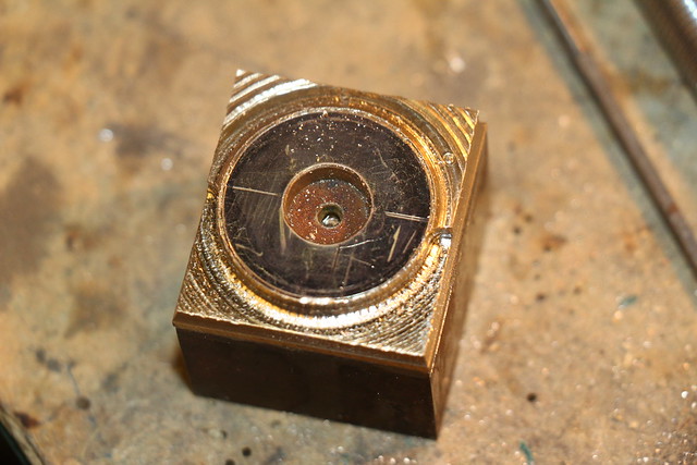 IMG_2133 IMG_2133 by Michael Cawthorne, on Flickr I then used a carbide disc in my mini drill to smooth out the shape, followed by a rubberized carborundum disc to further remove the cutting marks. Finally, fine wet and dry was used to give it a final finish. 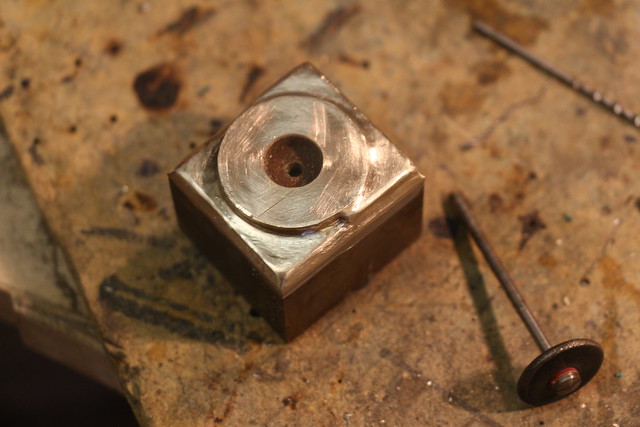 IMG_2134 IMG_2134 by Michael Cawthorne, on Flickr New axle box covers from Adam were then added, along with the securing nuts and bolts. I also added a 10ba brass bolt and nut filed down to represent the grease nipple. 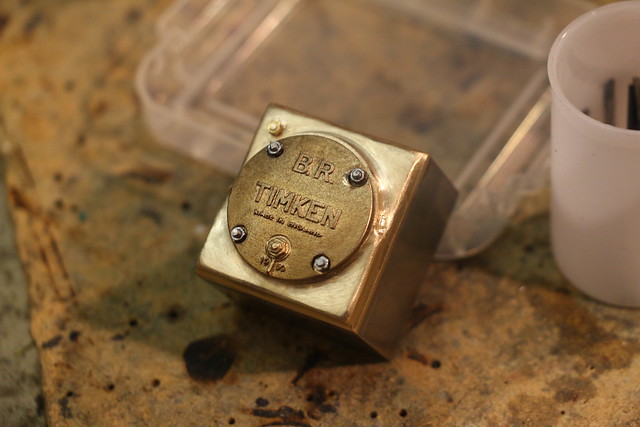 IMG_2138 IMG_2138 by Michael Cawthorne, on Flickr Unfortunately these will be painted black for my period, not being painted yellow until later. That just about finishes the suspension improvements, I'm glad I did them, I think it makes the tender chassis look a lot more realistic and didn't take a lot of extra work to do. Next I will have a look at the outside bearing for the water pick up apparatus which can be improved quite a bit (like having the right number of holes in it for a start). Regards Mike |
|
|
|
Post by Jim on Mar 17, 2018 4:46:51 GMT
I should really paint mine black too Mike as like you, the yellow covers were too early for my version of 70036. They do look nice in yellow though.
Jim
|
|
barlowworks
Statesman
  Now finished my other projects, Britannia here I come
Posts: 878 
|
Post by barlowworks on Mar 19, 2018 17:21:18 GMT
Hi Everybody Just a quick update of the latest detailing part on my Britannia tender. This is the real outside bearing for the water pick up operating shaft from Britannia. The hole should contain the shaft but the water pick up gear was removed on the preserved Britannia's. It is bolted to the left hand side of the tender looking forward, the other side has a greasing point for the brake shaft bearings. My tender will have working water pick up gear but it will be pinned up securely when operating as a safety measure, I'm not going to rely on a chain with a loop on it hooked over the operating handle like on he real thing. 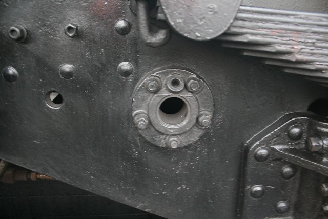 img_6352 img_6352 by Michael Cawthorne, on Flickr This is my attempt to model something a bit more accurate. The bearing on the right is the original one that came with the chassis. The one on the left is my attempt to make something a bit more realistic. Its not perfect but for me is a lot better. its even got the right number of holes in it  . These fixing holes will be spotted through to the chassis and when drilled it will be held on from the inside with 8ba bolts and washers and nuts on the outside like the real thing, not bolts into tapped holes.  IMG_2141 IMG_2141 by Michael Cawthorne, on Flickr I think the next thing will be the steps and the bracket that holds the water hose connection behind the steps. I think the steps will need to be made first to make sure the bracket fits properly. Soon be on with serious bits like the brakes and water pick up operating gear, that's all a bit more serious than just detailing. Mike |
|
don9f
Statesman
  Les Warnett 9F, Martin Evans “Jinty”, a part built “Austin 7” and now a part built Springbok B1.
Posts: 961 
|
Post by don9f on Mar 19, 2018 20:28:54 GMT
Hi Mike, nice to see your “improved” axleboxes and scoop shaft bearing! I did a similar thing on my tender but haven’t actually got a scoop....just a dummy shaft in the bearing. If you wanted, you could mount a 2 way grease block on the studs & nuts up and to the left of the bearing (visible in your photo). The grease pipes to the bearings on these tenders were 3/8 inch which scales to .033 and thanks are due to ’springcrocus’ (on here), who kindly supplied some old imperial electrical copper wire that was just right to make dummies.
Cheers Don
|
|
barlowworks
Statesman
  Now finished my other projects, Britannia here I come
Posts: 878 
|
Post by barlowworks on Mar 20, 2018 7:26:50 GMT
Hi Don
I hadn't noticed the mounting bolts and hole for access to the inside bearing, I thought the greasing point was only on one side. Now I think about it that never made sense. Something else to add to the list.
Mike
|
|
barlowworks
Statesman
  Now finished my other projects, Britannia here I come
Posts: 878 
|
Post by barlowworks on Mar 26, 2018 19:04:11 GMT
Hi everybody Prompted by Don's post I felt I must have a go at the grease feed box. This is my attempt at it. The water pick up outer bearing has now been spotted through and bolted on though I forgot the washers so it will have to come off again. I may check the bolt lengths when I do this as I think the bolts are a little long. I also turned up a fitting to go into the greasing point at the top. 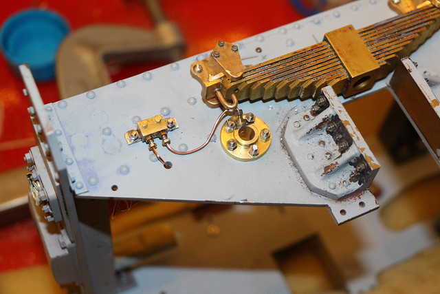 IMG_2148 IMG_2148 by Michael Cawthorne, on Flickr The grease box is just some scrap brass squared up in the mill and soldered to a strip of nickel silver for the mounting bracket. The front grease nipples are 12ba nuts on a piece of 12ba studding set into the front. The pipe connections are built round some brass tube I had that is 0.9mm i/d which was ideal for the 0.9 copper wire I used. Detail was built up from 10ba nuts and the 0.9 copper wire (actually 0.87) was obtained from that well known auction site as used by card makers and jewelers. This is super glued into the tube as I didn't want all my hard work to fall apart when soldering it in. It is all held on with 8ba nuts, bolts and washers. The other end of the 0.9 mm wire is just a push fit into a 0.9mm hole in the bearing at the moment with a 10ba nut to cover the joint. The other grease box for the other side is nearly complete, unfortunately I used up my supply of 10ba brass nuts. So after all that hard work I think the next thing will be to cover it all up with the front steps.  Mike |
|
|
|
Post by Jim on Mar 27, 2018 5:50:53 GMT
That happens to a lot of the fine detail that is put into models Mike but the thing is, you know it's there and it is something that you can take well justified pride in making and fitting. Lovely detail work.
Jim
|
|
barlowworks
Statesman
  Now finished my other projects, Britannia here I come
Posts: 878 
|
Post by barlowworks on Mar 27, 2018 13:47:48 GMT
Hi Jim You mention hidden detail. This is what I was doing on the modelling table at the resent Sheffield model railway show. Its the backhead of the A4 I am making in O gauge (not yet complete). All included in the kit and mostly unseen when its completed. Mike 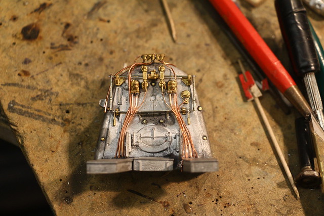 IMG_2149 IMG_2149 by Michael Cawthorne, on Flickr |
|
|
|
Post by Cro on Mar 27, 2018 13:55:51 GMT
Mike is this from the kit that was serialised in a magazine from the news agents? Dad has all the editions to do one and has started it but we never sourced the gearbox and motor - can you recommend one??
Tender bits are looking great by the way!
Adam
|
|
barlowworks
Statesman
  Now finished my other projects, Britannia here I come
Posts: 878 
|
Post by barlowworks on Mar 27, 2018 14:43:32 GMT
Hi Adam
This is an A4 by DJH models. I think they were the ones that produced the parts for the one in the magazine. I do not know your dads skill level but I would not recommend one to a beginner, they are very fiddly and a lot of the bits are to scale size and thickness. I have been building for 40 years and am struggling with this one. The motor and gearbox is by a company called ABC, probably the best on the marked but the price reflects that. If I can help in any way drop me an email or PM.
Mike
|
|
|
|
Post by Cro on Mar 27, 2018 14:48:27 GMT
Mike,
Thanks I will look them up, his Bday around the corner and this jogged my memory I was going to look for the bits.
He's a clock and watch maker by trade and built models as a child but not one like this. The cab structure is done and the main chassis is on its way and then it came to a hault so be good to get him back on it and hopefully between us we can manage something respectable.
Adam
|
|
barlowworks
Statesman
  Now finished my other projects, Britannia here I come
Posts: 878 
|
Post by barlowworks on Apr 6, 2018 20:12:49 GMT
Hi Everybody First of all, just to finish off the last entry, here is the grease feed box on the other side. The feed pipes will go through the hole directly below to feed the inside bearings for the brake shaft (not yet fitted). 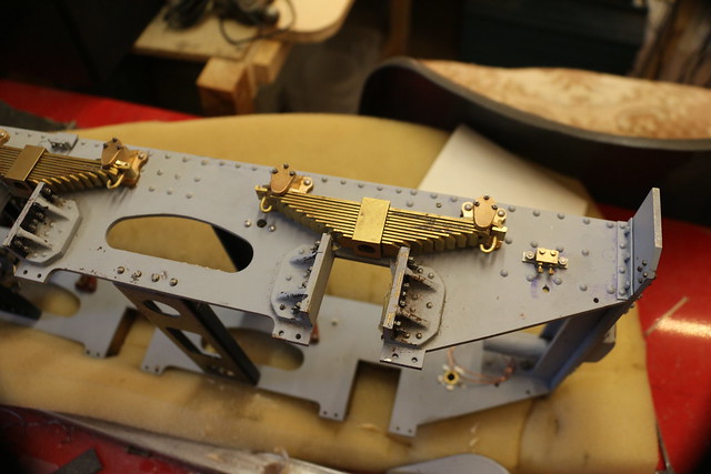 IMG_2151 IMG_2151 by Michael Cawthorne, on Flickr And so to the steps. There were some step back plates already cut out for the loco and tender in the parts box that came with the loco. Problem one was they were not wide enough and problem two was they were made of aluminum, not the most durable of materials for this application and as I wanted to silver solder the steps on I had to remake them. This is what we are aiming for, the rear step on Britannia. Things I noticed from this photograph were that the steps were welded on not riveted like on the Perrier and Wernett drawings. They were also held on with three brackets all with 2 bolt fixings. 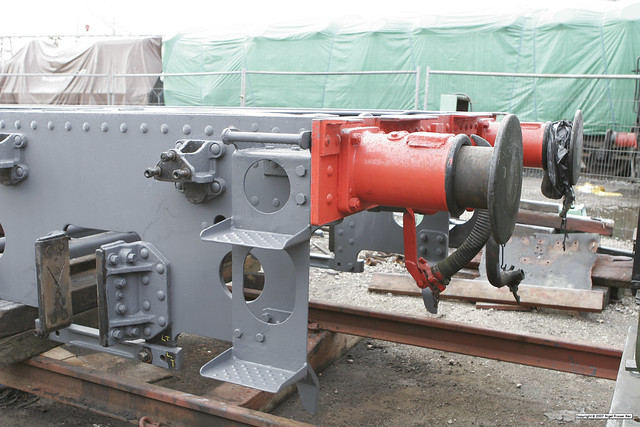 _MG_0124 _MG_0124 by Michael Cawthorne, on Flickr These are the step back plates made from some .48 nickel silver that I had left over from the O Gauge modelling days. I eventually used the dimensions from the Les Wernett 9F BR1 tender as they seemed to the most accurate. 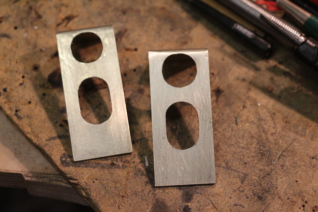 IMG_2152 IMG_2152 by Michael Cawthorne, on Flickr These are the steps also bent up from nickel silver. My past record of bending anything to size is not good but these all came out spot on. I will have to find out why. 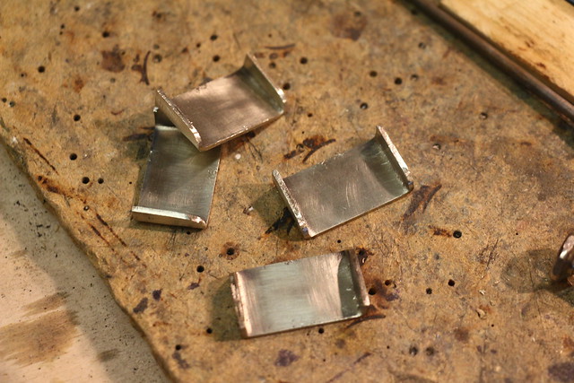 IMG_2158 IMG_2158 by Michael Cawthorne, on Flickr These are the clamps I made to hold the steps in place, not entirely successful but they lasted long enough to let me silver solder the steps on (that and a lot of Anglo Saxon). 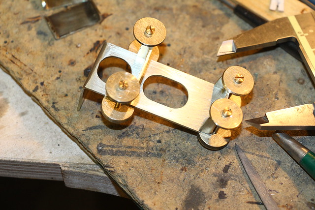 IMG_2161 IMG_2161 by Michael Cawthorne, on Flickr These are the steps after silver soldering. This is my first attempt at silver soldering and must admit to feeling a bit smug, it came out a lot better than I could have hoped. This is what they look like after a blast in the shot blasting cabinet. What is the process of cleaning up after silver soldering, the blasting worked o.k. but what if I wanted a smooth finish after soldering on something like steel. Also when do you pickle after silver soldering and is a ultrasonic bath a way of cleaning up afterwards. Please feel free to impart your wisdom, any help will be greatly appreciated. 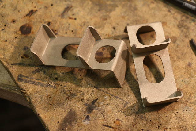 IMG_2162 IMG_2162 by Michael Cawthorne, on Flickr These are the top handrail supports held at the correct distance apart by a bit of old 6ba studding and some bolts. I thought both sides were the same but a photograph I have of Oliver Cromwell showed that the one next to the buffer beam was different so it was duly modified. 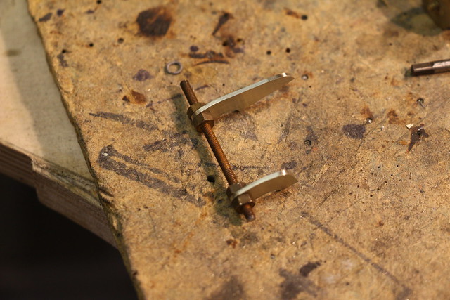 IMG_2166 IMG_2166 by Michael Cawthorne, on Flickr The supports were soldered on with some 224 degree soft solder which then enabled me to solder the handrail in place with 145 degree solder and not worry about everything falling apart. They should be o.k. soft soldered as the handrails are tucked up under the bottom of the tender tank. 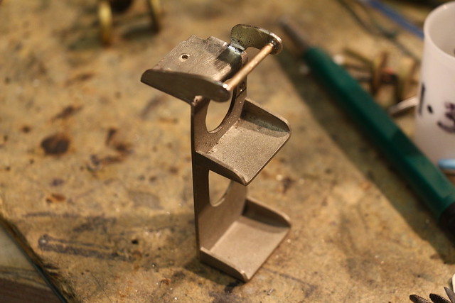 IMG_2168 IMG_2168 by Michael Cawthorne, on Flickr Finally, this is the footstep fitted to the rear of the tender. It has the correct brackets with the correct number of bolts which is what I set out to achieve. The bottom bracket uses the top two bolts of the axleguard fixings. Just the other side to complete. Oh, and the anti-slip tread plates on the steps, I may have an idea on how to do that.  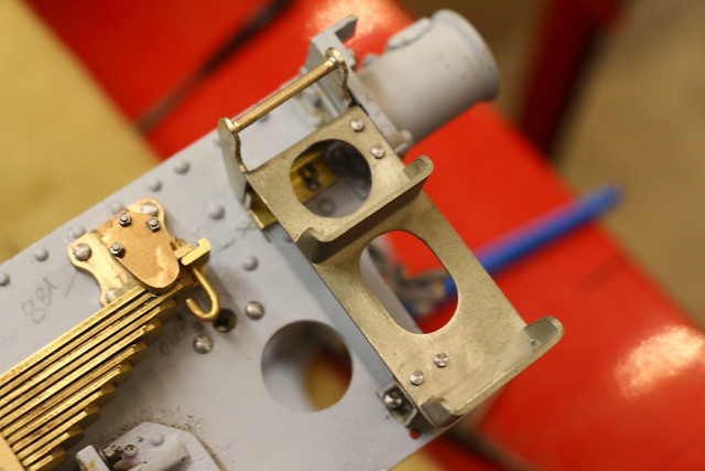 IMG_2175 IMG_2175 by Michael Cawthorne, on Flickr The front steps will have to wait as I have noticed they are suspended from the platform at the top of the tender chassis. Once the other side is completed I may make the guard irons to complete the rear end. Mike |
|
|
|
Post by Jim on Apr 6, 2018 21:44:42 GMT
Lovely work there Mike, it really is.
Jim
|
|
|
|
Post by springcrocus on Apr 6, 2018 22:34:52 GMT
Some beautiful detailing going on here, Mike, lovely work.
Regards, Steve
|
|
barlowworks
Statesman
  Now finished my other projects, Britannia here I come
Posts: 878 
|
Post by barlowworks on Apr 8, 2018 15:51:04 GMT
Hi Everybody To finish off the steps I needed to add the anti skid surface. This finish looked very much like embossed rivets from my O gauge modelling so I dug out my rivet embossing tool. It works by dropping a weight onto a stop on a striker that lines up with an anvil with the rivet shape impression on it. This one is now getting on for 40 years old and I hate to think how many thousands of rivets I've embossed with it. Once, at a modelling table at a local railway exhibition I embossed over 500 rivets in a weekend on a GWR bogie iron mink wagon. 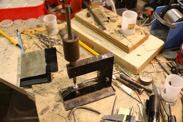 IMG_2176 IMG_2176 by Michael Cawthorne, on Flickr All my anvils are to produce scale rivets in O gauge so were not big enough for the anti skid plates so I turned up a bigger one. Funnily enough the striker I use for O Gauge worked o.k. with the bigger anvil. I tried some 8 thou nickel silver but the rivets punched right through leaving holes in the sheet. I eventually settled on 18 thou, a bit thick really but it gave a nice crisp embossed rivet. 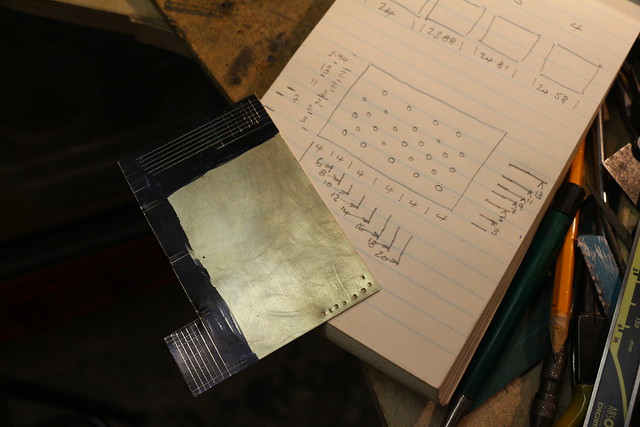 IMG_2183 IMG_2183 by Michael Cawthorne, on Flickr The anti skid surface on the rear steps consists of 6 alternating rows of 5 and 4 rivets. After measuring up the step sizes I worked out a grid to help with the embossing. 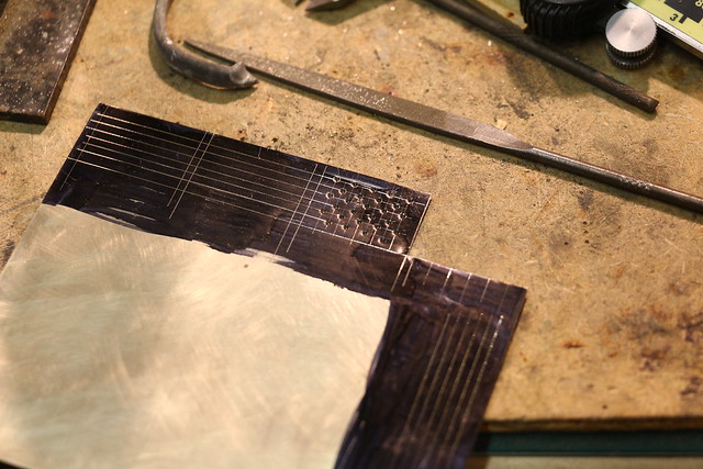 IMG_2177 IMG_2177 by Michael Cawthorne, on Flickr All this marking out is on the reverse so will not be seen. On the riveting tool there is a depth stop which is essential for punching the rivets in a straight line. Take great care with the first rivet on each row and then with the striker still in the hole adjust the depth stop, the rest on that row just need to line up with the lines on the grid. 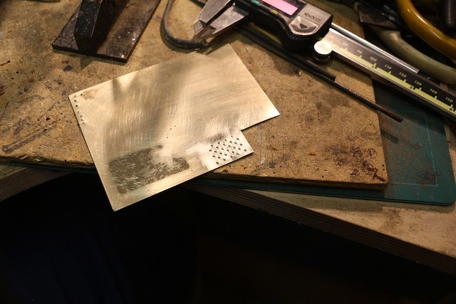 IMG_2181 IMG_2181 by Michael Cawthorne, on Flickr This is the anti skid finish just waiting to be cut to size. 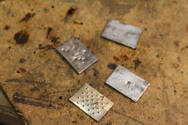 IMG_2190 IMG_2190 by Michael Cawthorne, on Flickr The step plates were then tinned with 145 degree solder, the steps also being tinned. 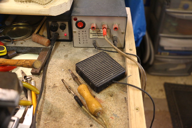 IMG_2191 IMG_2191 by Michael Cawthorne, on Flickr This is my secret weapon, a resistance solderer. As you can see it lives permanently under the rubbish on my work bench and is another piece of kit I could not do without in O Gauge. 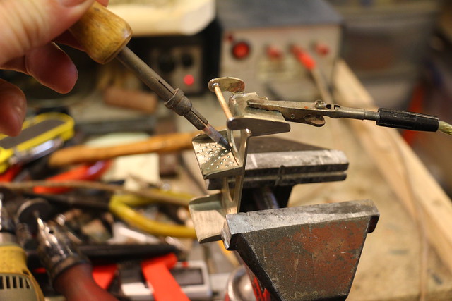 IMG_2195 IMG_2195 by Michael Cawthorne, on Flickr It works by passing a low voltage, high current through the work piece, one side being clipped on and the other is a carbon electrode that produces localized heat at the electrode tip. It is especially useful at attaching small components to much larger ones were the heat in a soldering iron would be sucked away by the larger component. Here I am using it to attach the anti slip plates to the steps ( you could probably do this by sweating them on with a small flame but the resistance solderer makes it so much easier). This is the reason I wanted to silver solder the steps on in the first place. 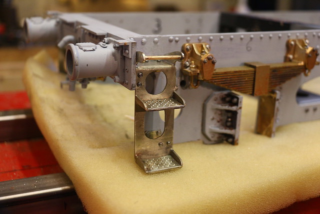 IMG_2198 IMG_2198 by Michael Cawthorne, on Flickr Finally, this is the completed step in place on the chassis. Next will be the guard irons which should finish the back of the chassis. Mike |
|