nonort
Part of the e-furniture
 If all the worlds a Stage someone's nicked the Horses
Posts: 277 
|
Post by nonort on Jun 5, 2020 18:17:08 GMT
Very interesting that the tee bar is bolted to the cab not riveted? Any idea how the hand rail is fixed at the bottom to the running plate?
|
|
|
|
Post by GeorgeRay on Jun 5, 2020 20:52:40 GMT
Ed
I think you will find that they actually carry the weight of the tank according to all the literature on Terriers. They do also hold down the lagging.
George
|
|
|
|
Post by terrier060 on Jun 6, 2020 0:39:19 GMT
Not quite sure what you mean nonort.
George, do you have any info on what the top of the tanks were bolted to because if you look at them fitting them at Bressingham there does not appear to be anything other than the lagging. I agree though that with all those large bolts and the size and weight of the tanks one would think there was more than just the thin steel lagging sheet holding them. Maybe I should try and contact one of the engineers at Bressingham.
|
|
|
|
Post by GeorgeRay on Jun 8, 2020 21:30:35 GMT
Ed
I’ve been searching the literature that I have and the description I have found says.”Although resting on the running plates and on the upper edges of the frames, the tanks were suspended from a plate passing over the top of the boiler, which meant that there was little distortion of the running plates; brackets were not required for their support. For these reasons Stroudley preferred the term ‘wing tank, to ‘side tank’.” I thought I had some pictures somewhere but I can’t find them.
George
|
|
jma1009
Elder Statesman

Posts: 5,901
|
Post by jma1009 on Jun 9, 2020 20:26:47 GMT
Hi Ed,
To add to George's comments, there was an inverted 'U' of iron of 'L' section around the backhead inside the cab up against the inside of the cab front spectacle plate, and to which the front spectacle plate was bolted to and the rear of the tanks. (Don Young replicates this on his 'Newport' design and goes into some detail on all this).
The tanks when full were not that heavy - was it 450 gallons?, but nevertheless the running boards were not well supported, and it would seem that the rear boiler cleading provided the main support for the tanks as a 'saddle' over the lagged boiler top, and at the rear the 'U' of 'L' section inside the cab.
I have found no photographic evidence of any other fixing or support method. Martello, Fenchurch, and Stepney still have their original rear boiler cleading, much patched due to the Marsh boiler dome being slightly further forward, and the addition of steam injector valves fore and aft of the dome variously.
This would account for the number of bolts used to attach Martello's tanks to the rear cleading in the Channel 5 programme?
Cheers,
Julian
|
|
|
|
Post by terrier060 on Jun 9, 2020 21:49:09 GMT
Thanks both. I think that makes things fairly clear. No way the tanks are going to fall off sideways!
|
|
|
|
Post by jbentley11 on Jun 10, 2020 10:07:35 GMT
The following link (to my OneDrive folder) should provide access to a number of Terrier drawings including 2125 which covers the cab for the first batch of Terriers. There are a number of differences to the later batches, but I believe that the beading and handrail details apply to all 50 Terriers. 1drv.ms/u/s!Av-PnPD3NUIziAczEwhvrCkiED9L?e=ulofUk A number of the drawings are redrawn from the original drawings and show a number of later modifications such as the tank drawing 2074 which shows the later fixing arrangements for the clothing plates and a pocket to accommodate the later type of reversing rod. I have also included drawing 4128 which is a not a Terrier drawing, but shows the original method of fixing tank clothing plates with shear head bolts. Hopefully these should help. I am happy to answer any questions if I can. Regards, John |
|
|
|
Post by jbentley11 on Jun 10, 2020 10:16:33 GMT
The system removed the (https://) from the above link. If you add the missing (https://) in front of the above the link works.
|
|
jma1009
Elder Statesman
Posts: 5,901
|
Post by jma1009 on Jun 11, 2020 22:41:10 GMT
Sorry, John, your link didn't work at all.
If you have some of the works drawings I am sure quite a few of us would be very interested to see them!
Cheers,
Julian
|
|
|
|
Post by Jim Scott on Jun 12, 2020 9:00:01 GMT
Hello John and welcome to the MECH Forum. Many thanks for sharing your photographic record of some of the original Terrier drawings. I'm intrigued as to how you were able to access and photograph them so comprehensively. They are a great original reference as well as as being of significant historical interest. I have spent some time browsing through them and have downloaded one or two of particular interest. As many drawings have been photographed in part as well as complete folk will need to work out which photos are best suited to their needs. If you have any further Terrier related stuff it will be well received on this forum, in your own thread if needs be. Cheers Jim Scott (Earlswood 83)
The full link to share John's OneDrive folder is: (https://1drv.ms/u/s!Av-PnPD3NUIziAczEwhvrCkiED9L?e=ulofUk) Note: You will need to copy the address between the brackets and paste it into your browser. |
|
|
|
Post by terrier060 on Jun 12, 2020 19:43:52 GMT
John - I have just seen your link and I thank you to the bottom of my heart. I love the watercolour tint. It reminds me of one of my first jobs, when in my late teens I worked for the Winchester Water Undertaking (nothing to do with sewage in those days). There were a lot of large scale drawings of the pumping station (late 1800s) and the beam engines, all beautifully coloured. Even the 1:500 street maps were coloured, with even a plan of the individual gardens. No overhead cameras in those days, they must have been individually surveyed. I was lucky enough to have one of the English dial clocks that hung in the beam engine house. I remember having to clean off layers of grime (years of oil and steam) to find a beautifully preserved mahogany case beneath! I always joke that I knew Winchester better underground than I did on top, as one of my jobs was to trace lost water mains. One day I was tracing one through this wood and came across a standpipe. It had been illegally tapped into the main to water the Pheasants! I traced it eventually to the cellar of this large country house. It turned out to be a 6" high pressure water main with a fire hydrant at the end of it!!
I just wish I had had these drawings 30 years ago. My models are based on copious measurements of several preserved locos, plus the drawings in 'The Engineer' and 'Engineering' magazines. I will be studying these original drawings with great interest. I don't suppose you have details of the valve on the RHS of the smokebox, which I assume is something to do with lubrication!
Thanks again John - one very happy ME!
Ed
|
|
jma1009
Elder Statesman
Posts: 5,901
|
Post by jma1009 on Jun 12, 2020 23:24:41 GMT
Hi John,
OMG!
Thanks to Jim, and Phil (via PM), sorting out your link! Wonderful! You are a 'star' and do please tell us more... and what got you to go up to the NRM presumably and take all these pics of the original drawings, none apart from the GA I have found cataloged at the NRM.
Quite amazing!
Cheers,
Julian
|
|
|
|
Post by terrier060 on Jun 13, 2020 19:02:40 GMT
George, are we allowed to reproduce parts of these drawings on this thread for research purposes, or would I be infringing copyright?
The drawings are great. They show a very early version of the A1 (the version I am building) with only one water gauge glass and two test cocks. I don't know if any boilers were build to these drawings, or whether they decided to go for the standard two glasses?
The cab drawings also clearly show a 2 foot section of beading running along the roof, so that makes machining the beading much easier.
Also Julian was quite correct that the very ends of the beading is shown flared, but from the photos it looks like this was ignored as an unnecessary complication, at least on some of the engines.
Ed
|
|
|
|
Post by jbentley11 on Jun 20, 2020 18:36:58 GMT
I am glad that the drawings are useful to people. Technical these photos are for private study only and so I suggest that they are not uploaded to this site.
Thank you to Jim for clarifying how to include a link.
A list of all of the NRM’s Southern locomotive drawings, which include those produced at Brighton, is available via the following link – (https://www.railwaymuseum.org.uk/sites/default/files/2020-03/Southern%20Railway%20Locomotive%20Drawings%20and%20Microfilm%20Lists.pdf).
I have added three new folders. These include:
• A folder called “Fittings” that includes the lubricator for the righthand side of the smokebox, Strouldley’s speed indicator (Brighton was the only Terrier fitted with on), Stroudley’s air brake valve and a later drawing of Stroudley’s water gauge after gauge glass protectors were added;
• The drawing of the number plates cast for Waddon’s restoration; and
• A folder showing the frames of my own long-term project in 5” gauge.
The lubricator for the righthand side of the smokebox was produced for the replacement manufacture as part of Waddon’s restoration. I was planning to ask Adam of Cro Castings if he would consider producing castings for these, together with other the Stroudley lubricators and other standard parts such as check valves.
I have also uploaded a PDF of William Stroudley’s paper “Construction of Locomotive Engines” of 1885 that contains much useful information on Stroudley’s thinking. For those interested in Stroudley’s designs I can recommend “William Stroudley Craftsman of Steam” by H. J. Campbell Cornwell published in 1968 which is a technical biography. Another book worth reading is “Locomotives of the LBSCR” by D. L. Bradley.
I hope this is of help.
Regards, John
|
|
|
|
Post by Jim Scott on Jun 20, 2020 23:35:10 GMT
John My astonishment continues unabated...... There are usually two reactions when folk realise that someone is building a model similar to their own but to a much higher standard. Either they are galvanised into action to strive even harder to produce something to the best of their ability or else they throw their meagre efforts into the scrap bin and start again. I will pursue the former course of action whilst hopefully seeing an occasional photo of how good it could have been. Please keep us updated with your progress and photos to drool over. Respecting your wish not to publish photos of documents, plans, etc. I hope you don't mind me including a photo of your own model frames here for the benefit of those who haven't looked at your OneDrive folder. Thanks again for allowing this information to be viewed, it is a real treasure trove. Ed has already commented that had this info been previously accessible it would have been invaluable to those of us who started their builds many decades ago. Regards Jim S 5" Gauge Terrier Frames by John Bentley |
|
jma1009
Elder Statesman
Posts: 5,901
|
Post by jma1009 on Jun 21, 2020 23:06:00 GMT
Hello John,
Many thanks for posting all the further NRM drawings via dropbox and pics of your loco frames. It is a very valuable resource. Jim's example and mine are pretty much at the final stage of construction/completion so we are are not going to alter anything; indeed I think we have it pretty much 'as is' to the drawings though in 5"g certain compromises are required.
There is a Brighton Terrier facebook page plus another for the Isle of Wight Railways pre 1966 plus the IOWSR face book page. Would it be in order to post the link to your dropbox pics on these sites? Copyright is lost/infringed apparently on facebook, so this requires some consideration on your part, and I would not do so without your permission.
(Nice to note that the original drawings at the NRM confirm my own view and that of George Ray as to those flared out 'comma' styled cab opening 'T' section!)
Cheers,
Julian
|
|
|
|
Post by jbentley11 on Jun 27, 2020 10:02:42 GMT
I apologise for the delay in replying, but life is very busy at the moment. Jim, thank you for your kind comments. This is very much a long-term project I was initially inspired by the work of the likes of the late Bill Carter and Roy Amsbury.
Julian. I am not a fan of Facebook and would be concerned about direct links from Facebook to my OneDrive, however, you could provide a link to this thread.
Regards, John
|
|
|
|
Post by terrier060 on Jun 27, 2020 13:39:11 GMT
Great work there John - brings back a lot of memories when I started mine over 30 years ago! It is going to be a fine locomotive. Thing that amazed me is how flimsy the frames are with all the cut-outs, but by the time the T-sections and stretchers are added they become both light and strong. I also like the way the drag bar attaches to the stretcher immediately behind the rear horns. And such a pretty locomotive and advanced design for its day! Please keep the photos coming John as you progress. I will not post any works drawings on my thread, as you have rightly asked. I do put images of published works in 'The Engineer' and 'Engineering' as that is considered research material.
Ed
|
|
|
|
Post by terrier060 on Jun 27, 2020 15:21:27 GMT
Great drawings of the lubricator John - I only had some photos and my own measurements to go on. I wonder how to make the speedometer work in miniature? I think Stroudley used water didn't he? He also had a warning bell as well. 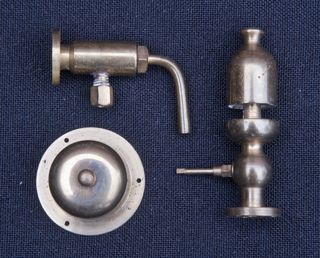 005 A1 Boiler fittings 005 A1 Boiler fittings by ed cloutman, on Flickr |
|
|
|
Post by ettingtonliam on Jun 27, 2020 16:28:14 GMT
Terriers had speedometers?
|
|


