|
|
Post by Roger on Feb 24, 2019 9:09:18 GMT
Well I am surprised that the amount of metal that can be removed at each cut is so small. Comparing it to a modest lathe, the lathe beats it hands down. If I could swing the length required in a lathe I would have gone down that path, even with interrupted cuts. My analysis is that there is enough power output from the mill to undertake more meaty cuts and the rigidity of the setup is good, no vibration so the weak link is the endmill, which is a new Sutton's one but not designed for roughing, so I will purchase a roughing one. Whilst I am awaiting delivery and it is going to be a dreadful week in Adelaide, another heat wave, I shall limit the activity to using the angle grinder to get nearer to the front elevation profile. If I was in the bush, this week is likely to be a total fire ban so I wouldn't be allowed to use the angle grinder, so I must be thankful for small mercies. Brian Hi Brian, I've not seen pictures of the Lathe and Mill enough to compare them, but I suspect there's an awful lot more metal between the chuck and the tool on the lathe. Small mills usually have a pitifully small and flexible column, and this is probably the reason why they aren't that capable. The construction seems to be aimed at being able to have the maximum traverse in each axis at the expense of rigidity. That's understandable really if you want it to be as flexible as possible. If you scaled down a Bridgeport to the size of a mini mill, I imagine you'd get less than half the traverse that your machine has. I doubt very much if the cutters will have much bearing on the capability of the mill, you won't be able to push very hard whatever you choose. Rippers take less load, but I don't think you can get them smaller than 5mm diameter and that's a bit big for a small mill to be pushing hard. I think your best bet is to look at modifying the machine along the lines of what Doug has done. If you PM him, I'm sure he'll be happy to share his before and after experience following the modification. In the end, the amount of metal and where it's put it in the mill structure more important than almost anything else when it comes to how much material you can remove in one pass. The column is the weakest link, and that's where I'd be looking to make the biggest difference for the least amount of effort. |
|
|
|
Post by runner42 on Mar 5, 2019 6:46:57 GMT
Well I overcame all the niggling issues with the milling machine, due mainly to set up and thereby complete the connecting rods. I have kept the small end at 12 mm due to the fact that my changed crosshead has a 1/2" slot, so the difference between the small end and crosshead is reduced and the side float be accommodated by the gun metal bearing. Still no sign of the driving and driven wheels, it looks like the cylinder castings are going to arrive before the wheels. I was hoping to have received the castings and have them machined and fitted to the axles by now. They say patience is a virtue but this is trying the patience of a ....... Brian  connecting rods connecting rods by Brian Leach, on Flickr |
|
|
|
Post by runner42 on Mar 7, 2019 6:15:51 GMT
Hooray the cylinder castings arrived today, a bit early in the day, I was on my run and the wife was on her walk so no one home which meant I had to traipse across Adelaide to pick them up from the Courier's Depot. It was a bit iffy whether the castings for Springbok was going to be suitable because the length which is a 1/16" shorter than the Black 5. However, although I initially thought that the castings were too short, opening the box in the shed with the drawing indoors I was confused on the length dimensions and said to myself sh*t. Hence, the photos showing the slight porosity that could affect the length after machining and the actual length displayed on the digital vernier. But all's well that ends well, because the actual dimension is 3 5/16". Not a lot of metal to play with but with careful machining it will be OK. 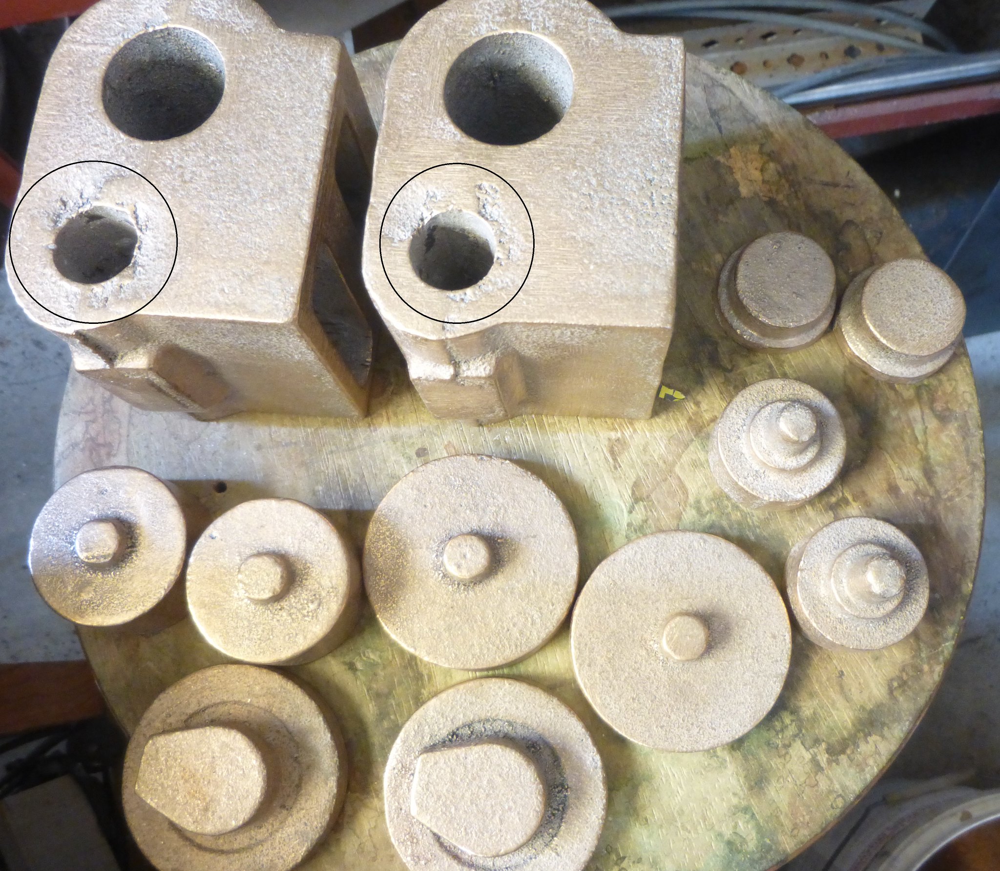 cylinder casting cylinder casting by Brian Leach, on Flickr 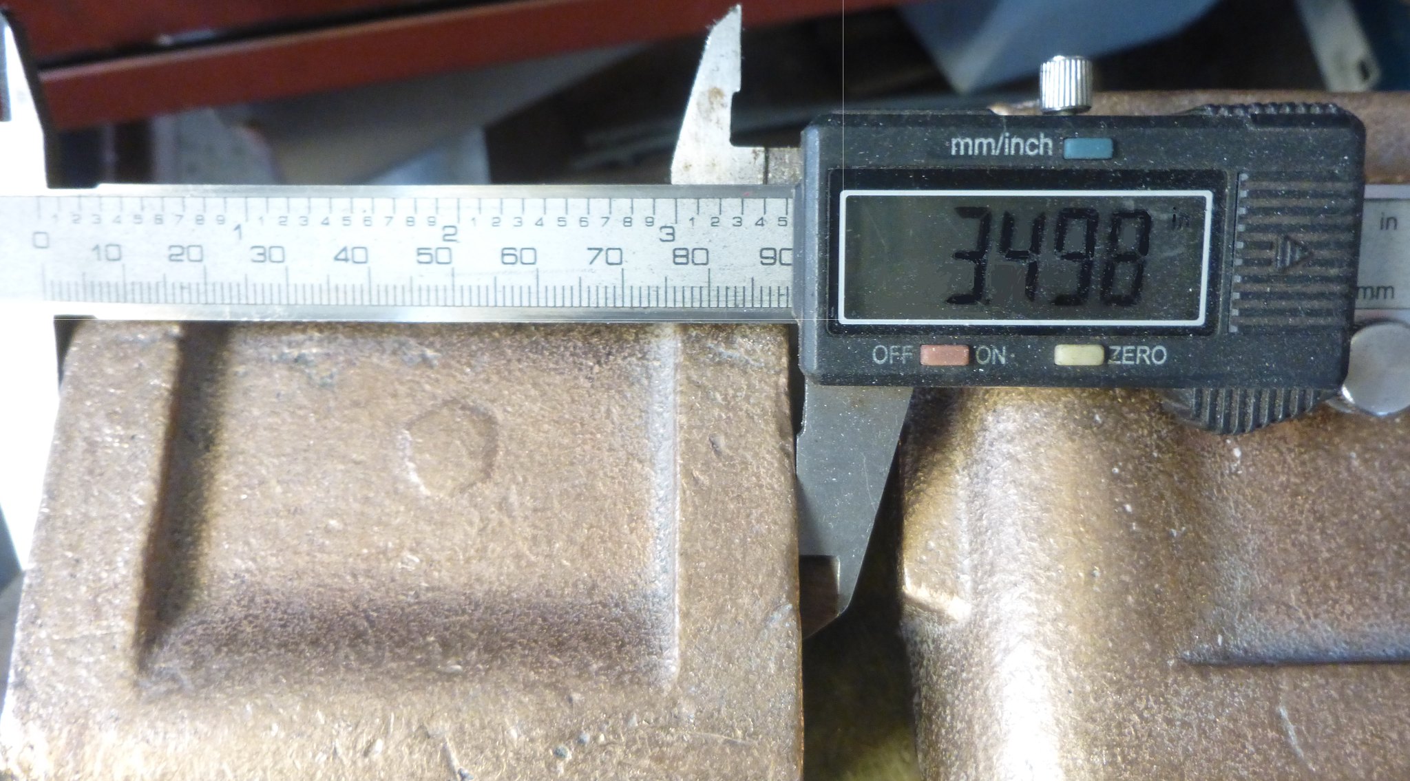 cylinder casting length cylinder casting length by Brian Leach, on Flickr PS I did a price comparison with AJ Reeves and their gunmetal cylinder set is 360.96 pounds plus a lot of postage costs. From E J Winter is costs $A385 delivered. Exchange rate is 0.53. |
|
JonL
Elder Statesman
   WWSME (Wiltshire)
Posts: 2,993
|
Post by JonL on Mar 7, 2019 7:07:03 GMT
Would you be sleeving the piston valve anyway? I hate the unpredictable nature of castings, but they do save a lot of work...
|
|
|
|
Post by runner42 on Mar 7, 2019 7:33:38 GMT
Would you be sleeving the piston valve anyway? I hate the unpredictable nature of castings, but they do save a lot of work... If you mean will I use a separate piston valve liner the answer is yes. This is made from just a length of gunmetal rod and I don't think it is usually included in the casting set. Brian |
|
|
|
Post by runner42 on Mar 15, 2019 7:41:50 GMT
Whilst I am awaiting my MT3 shank fly cutter for facing the cylinders to arrive ( I see Pete is using an end mill) I thought I would tackle an on the face of it a seemingly simple task of fabricating the smoke box saddle. Like most of my construction bits for the chassis I used 3 mm steel plate. It would have been straightforward if I had pinned the parts before silver soldering, instead I used my eye to judge a 90 deg corner which for 3 of them I was near enough but the fourth was not so good. So it required some de-soldering to get it right. Cutting corners (no pun intended) is you spend more time getting it right than if you had used correct procedures in the first place. However that was just the beginning, I decided to produce the exhaust pipe as it is an integral part of the smokebox saddle, I purchased some 3/4" copper tube which is designed to mate with 20 mm long radius 90 deg bends, however I have been unable to source these components so I went with short 90 deg bends which was a waste of time. I was not happy that the exhaust passage was too constrictive. I attempted to produce long 90 deg bends with the 3/4" copper tube which is a standard plumbing gauge but it is thin walled and impossible to bend without special tooling. I tried by inserting a number of cuts in halve the diameter with the intention of silver soldering these. The end result was a nearly acceptable exhaust pipe, but failed because the completed assembly could not be fitted to the smokebox saddle it had to be available during construction of box section. DY doesn't provide information on the drawing on how this is achieved. 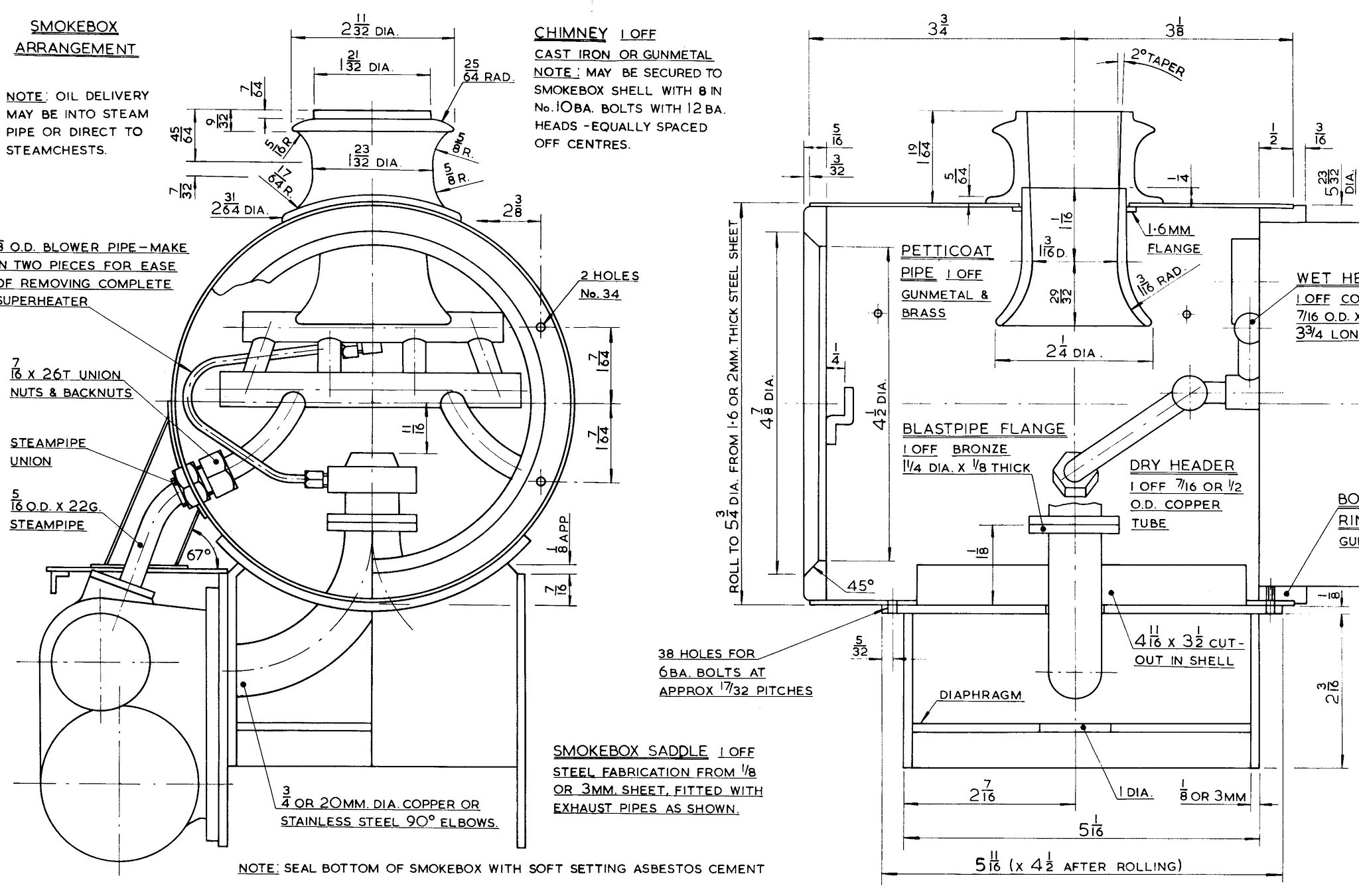 smokebox saddle drg smokebox saddle drg by Brian Leach, on Flickr 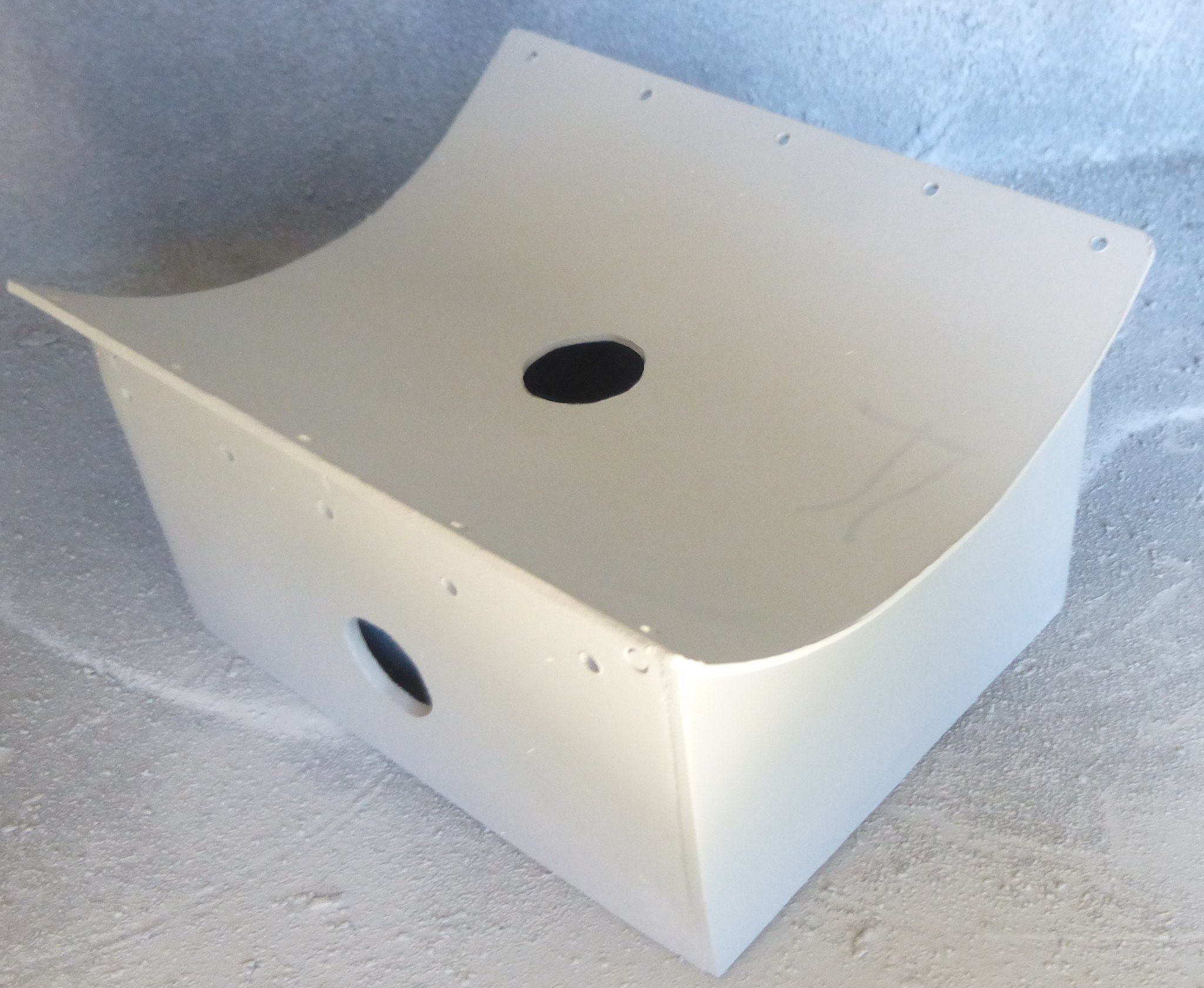 Smokebox saddle Smokebox saddle by Brian Leach, on Flickr On fitting the smokebox saddle to the chassis it became apparent that I will have to lower the mechanical lubricator because it will interfere with the smokebox. Brian 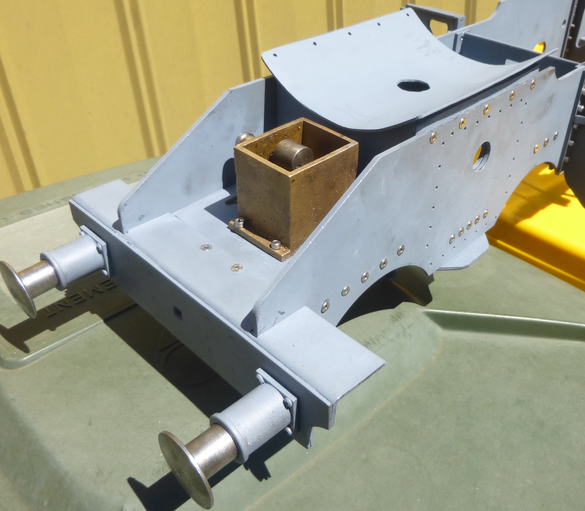 Smokebox saddle fitted Smokebox saddle fitted by Brian Leach, on Flickr 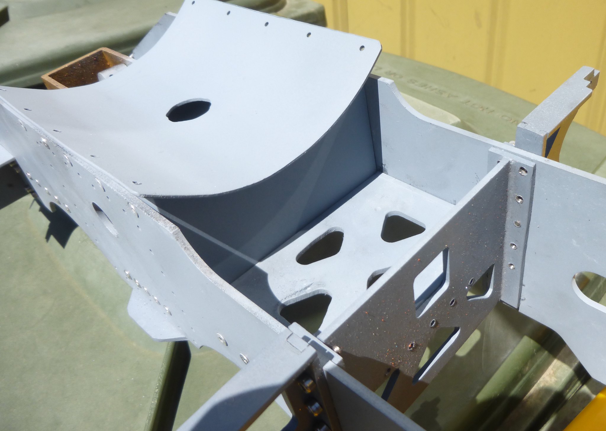 Smokebox saddle fitted1 Smokebox saddle fitted1 by Brian Leach, on Flickr |
|
|
|
Post by runner42 on Mar 16, 2019 6:40:28 GMT
Just a small step to start machining the cylinders. I have checked the raw casting and everything appears OK in terms of maximum metal condition and that the bolting face is reasonably at right angles to the bottom face shown in the photo, so I have elected to machine the top face first and then the bolting face. I would like some comment if this is not the optimum approach and indicate another machining procedure. Also I am utilising parts of the setup kit as spacers to lift the casting above the right angle block. I know these are not gauges but appear to be reasonably flat and parallel to be an option. Any other comments on the robustness or otherwise of the clamping setup. Brian 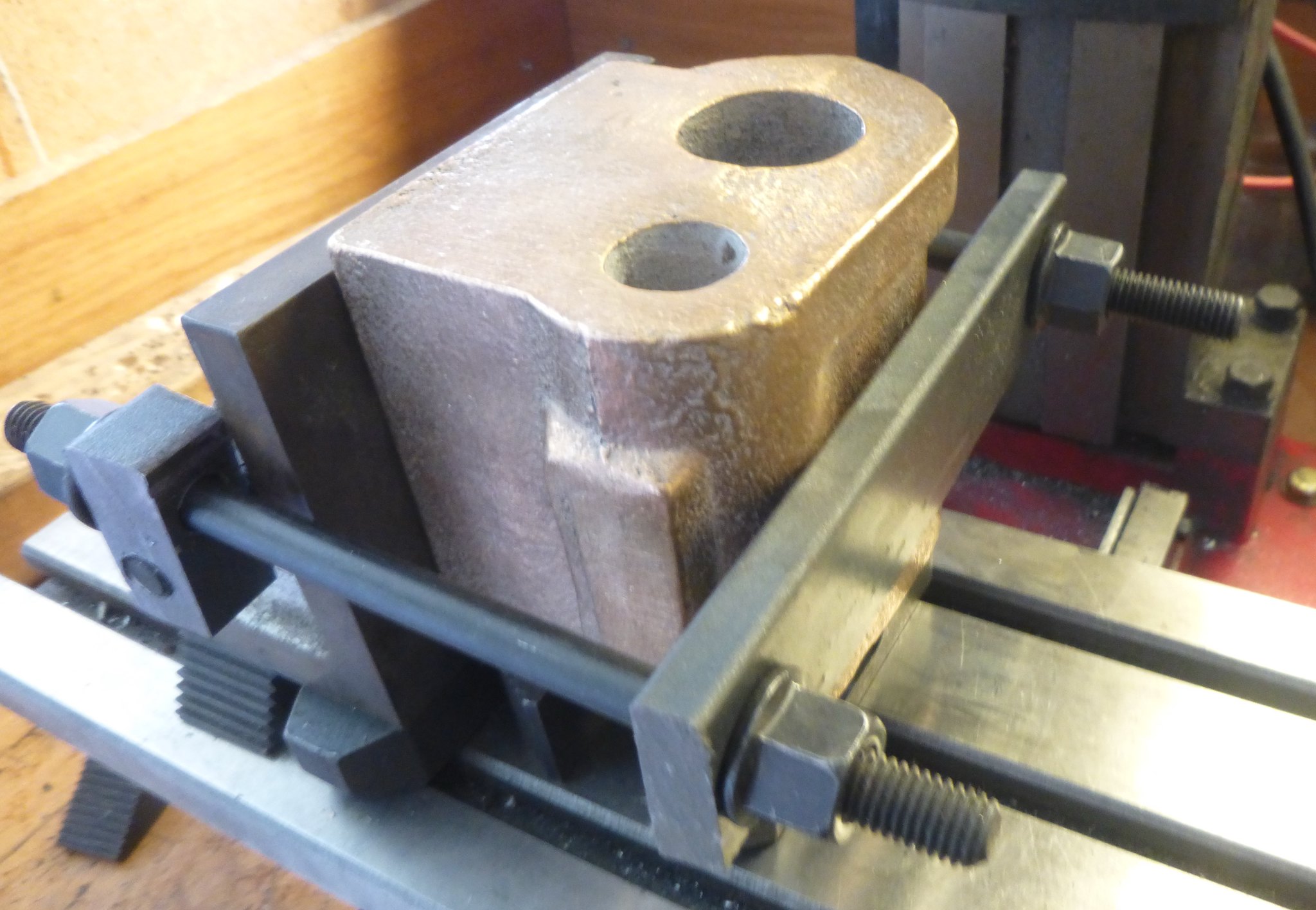 cylinder setup cylinder setup by Brian Leach, on Flickr 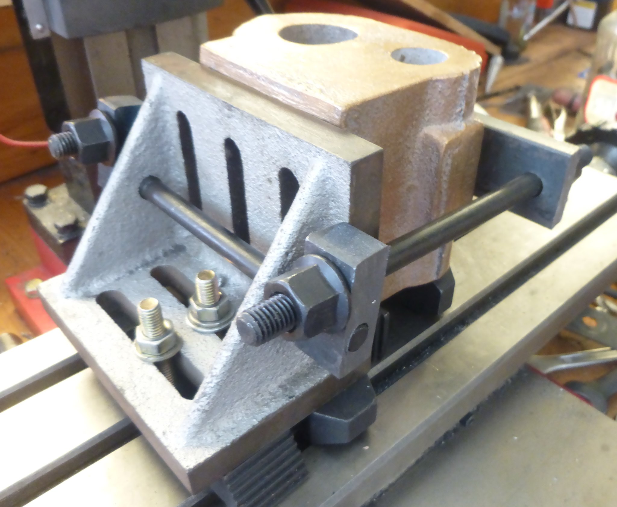 cylinder setup1 cylinder setup1 by Brian Leach, on Flickr |
|
|
|
Post by Deleted on Mar 16, 2019 7:21:26 GMT
Hi Brian
If I may comment, I wouldn't put any spacers under the angle itself, just bolt that flat to the bed. I'd get the casting as close to the bed as you can, some flat bar stock will do to bring the face clear of the angle. I have a large engineer's square that I then use off the column to check if the casting is square.
Regards
Pete
|
|
uuu
Elder Statesman
   your message here...
Posts: 2,864
|
Post by uuu on Mar 16, 2019 7:51:50 GMT
More hold-downs for the angle plate? If slots don't line up, then arrange a couple of finger clamps. Then the other end, you could add one on the bar holding the casting, to reduce any chance of lifting.
Wilf
|
|
stevep
Elder Statesman
  
Posts: 1,073
|
Post by stevep on Mar 16, 2019 9:00:50 GMT
Brian,
I think the main reason for castings moving when being machined is because the surfaces are so rough, and even when clamped tight, there is insufficient friction to stop the casting moving. This is often the case when castings are held in a machine vice.
The way around this is, of course, to get machined surfaces - so I try to start with very light cuts until I get a flat surface, and then re-position the casting to do another face, trying to use the previously machined surface against the reference surface (angle plate or milling machine bed).
When you are happy that you have something flat to clamp against, then you can start taking bigger cuts.
|
|
|
|
Post by Deleted on Mar 16, 2019 9:05:56 GMT
I forgot to say, I cut towards the angle in these situations, this greatly reduces the risk of things moving, I only take light cuts, takes time but is my preferred approach..
|
|
timb
Statesman
 
Posts: 512 
|
Post by timb on Mar 16, 2019 15:04:54 GMT
The only thing I would say is dont bolt the casting direct to any ground or true face, there is bound to be some hard spots or bits of sand on the cast face which will leave some annoying dings in your nice surface. I find brown wrapping paper (the thick stuff for parcels) does the job nicely and helps with friction too.
Tim
|
|
|
|
Post by ettingtonliam on Mar 16, 2019 15:05:07 GMT
I don't quite understand why you've packed up the angleplate itself. I'd have bolted it down flat to the table, probably using 4 bolts instead of just 2. Maybe then you wouldn't need packing under the cylinder block either?
A couple of pieces of 1" x 1/2" steel flat drilled to suit the tee slot spacings, bolted down, one each end of the angle plate helps to stop any tendency of the angle plate to move during machining, too.
|
|
|
|
Post by runner42 on Mar 16, 2019 20:43:41 GMT
I don't quite understand why you've packed up the angleplate itself. I'd have bolted it down flat to the table, probably using 4 bolts instead of just 2. Maybe then you wouldn't need packing under the cylinder block either? A couple of pieces of 1" x 1/2" steel flat drilled to suit the tee slot spacings, bolted down, one each end of the angle plate helps to stop any tendency of the angle plate to move during machining, too. You are right it was one of those situations where I was trying out certain things and thought there was a need to raise the angle block because it is a small one and having done that then in the further development needed to raise the casting above the angle block so I could undertake a full cut. Having done this it later dawned on me that if I didn't use them I would have a similar setup to what I was wanting to achieve. Brian |
|
|
|
Post by runner42 on Mar 16, 2019 20:52:12 GMT
Thanks for the replies all sound advice just what I was needing being a beginner in using a milling machine. The consensus is that I should beef up the clamping of the angle block to the bed, I too thought that this was the Achilles Heel.
Brian
|
|
|
|
Post by runner42 on Mar 19, 2019 7:30:07 GMT
I thought that it is a good idea to produce a cardboard template from the Black 5 drawing and apply it to the Springbok cylinder just to see what modifications I need to apply in the machining. The photo shows some difference in the position of the bores. In addition although it is not obvious from the photo is that quite a bit needs to be removed from the bolting face such that it will affect the cast cut outs for the exhaust. I will have to increase the depth of the bolting face by 4 mm and reduce the cylinder flange from 5 mm to 1 mm. This will become more of a closure from the rectangular cast exhaust port to the circular opening in the main frames. Brian 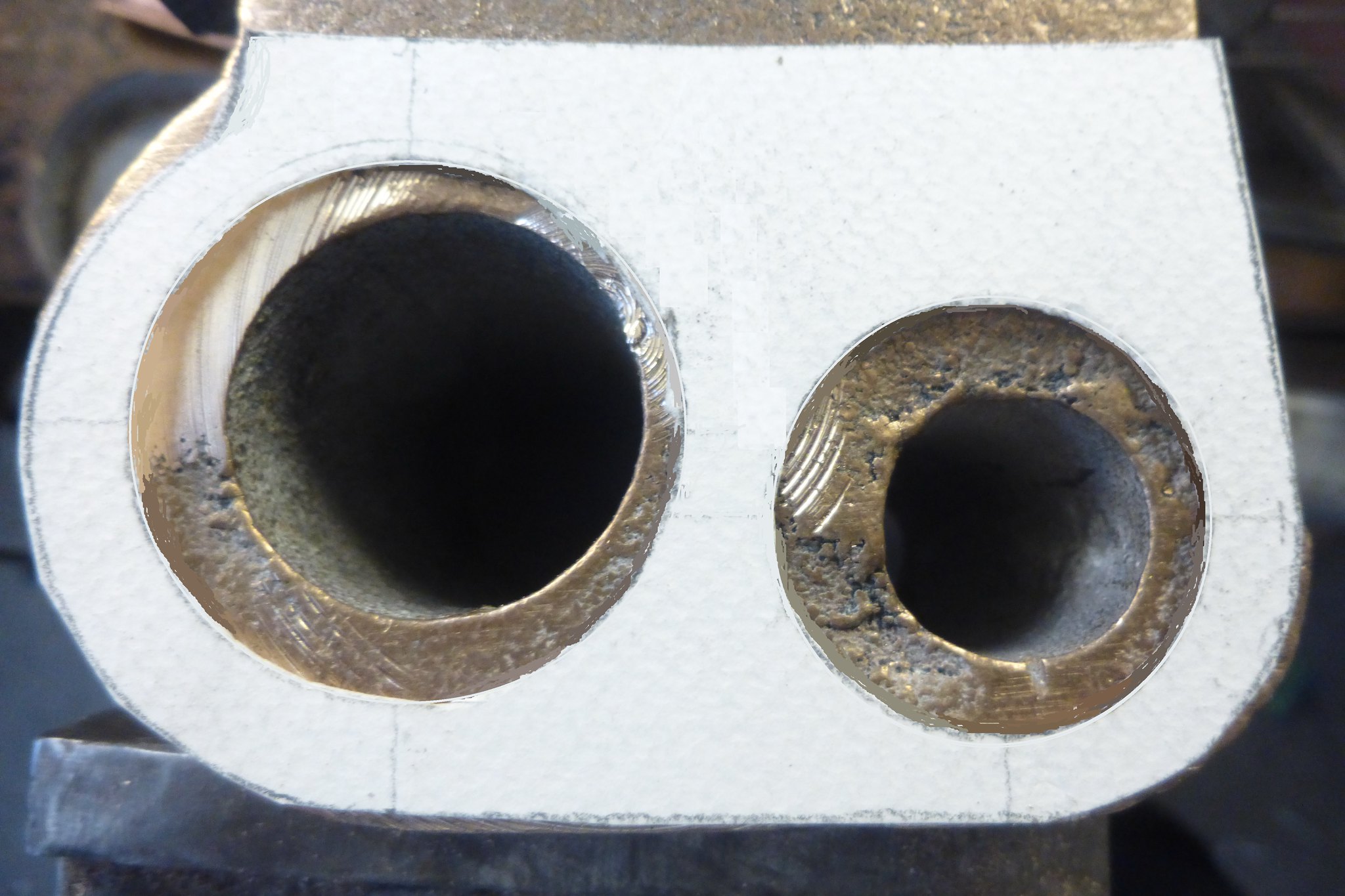 cylinder template1 cylinder template1 by Brian Leach, on Flickr |
|
|
|
Post by runner42 on Mar 20, 2019 6:53:45 GMT
Having received my 4 insert facing cutter I started on the ends of the cylinders being the most important facing operation. Although the setup appears very rigid there appears to be some very small variation in the Z axis such that at times one or more of the cutters digs in a produces a shallow groove. At first although the Z axis was stopped from inadvertently increasing the depth of cut by the large Z clamp I noticed that either due to backlash in the Z screw dial and or insufficient clamping of the small Z clamp that allowed the cutter to push away from the work piece and reduce the depth of cut over a single pass. I have minimized this as far as possible, I am still unsure what could be causing this to happen. At initial setup I didn't affix the 4 insert cutters sufficiently tight and one became loose and caused the mill to overload and stop. However I have fixed this so loose insert cutters are no longer an issue. Any ideas as to what is causing this intermittent slight variation in depth of cut? Brian 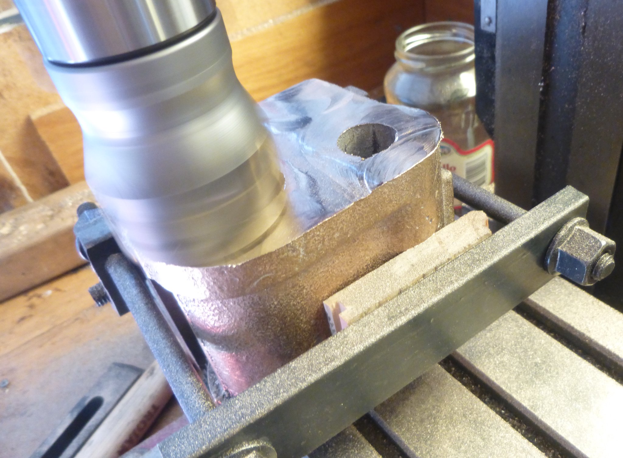 facing1 facing1 by Brian Leach, on Flickr 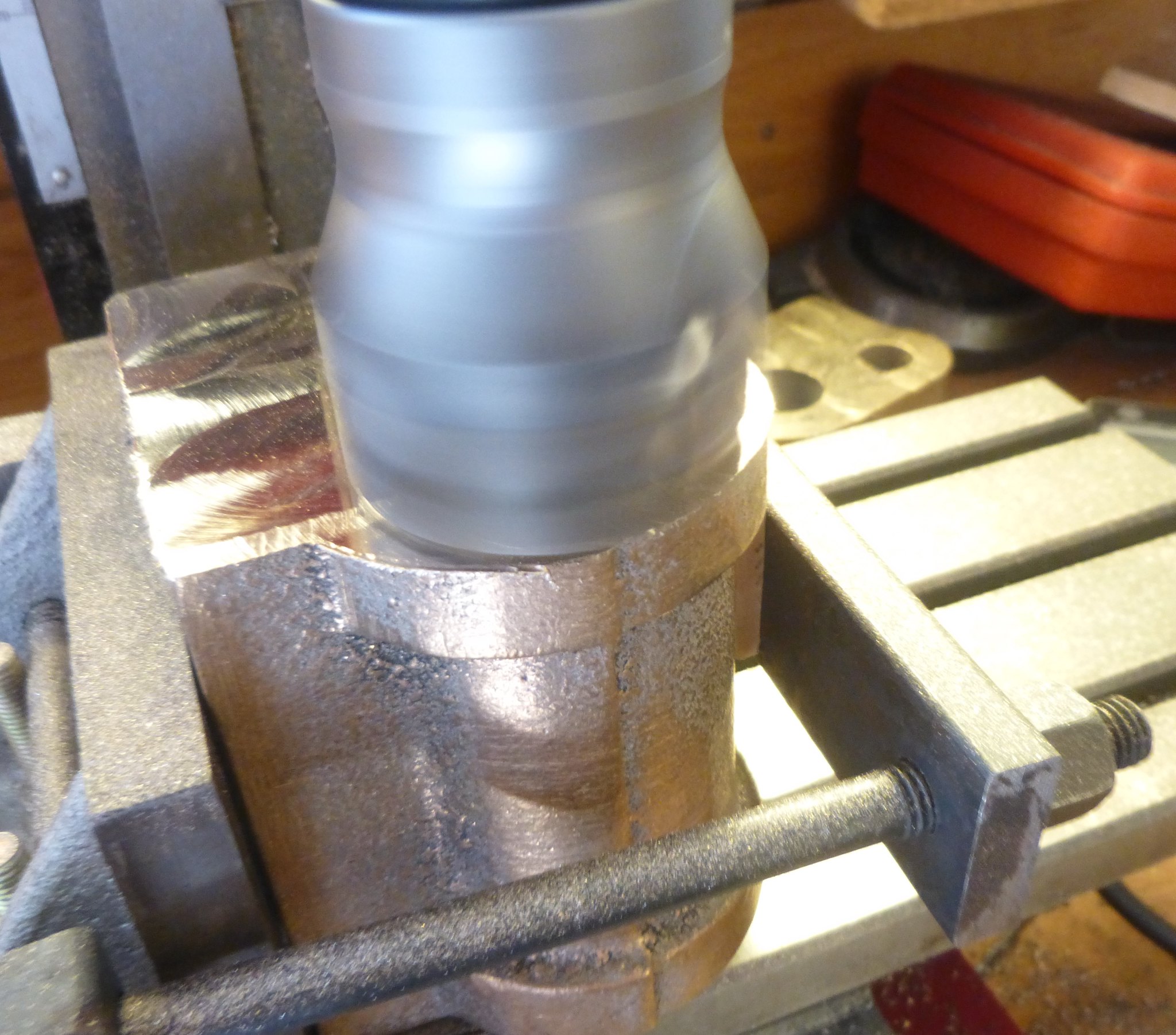 facing2 facing2 by Brian Leach, on Flickr 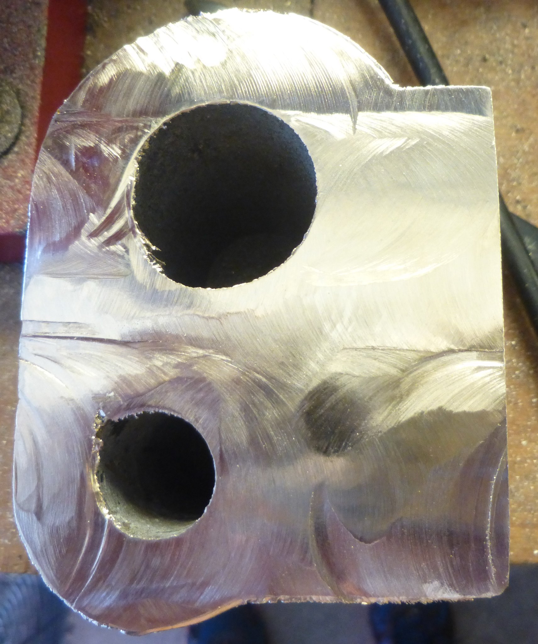 facing surface finish facing surface finish by Brian Leach, on Flickr |
|
|
|
Post by ettingtonliam on Mar 20, 2019 7:57:09 GMT
Are you sure the inserts themselves are tight, its not just the fixing screws bottoming out in the thread and seeming to be tight?
|
|
JonL
Elder Statesman
   WWSME (Wiltshire)
Posts: 2,993
|
Post by JonL on Mar 20, 2019 8:14:08 GMT
I have a couple of cheaper carbide insert tools and found that the screw could be tight and they would still turn half a degree or so in each direction if abused enough. I'm not saying this is happening but it might be worth revisiting, I thought mine were tight too. I removed the insert and cleaned under it and it improved things. I think I had a film of protective oil under the tip.
|
|
nonort
Part of the e-furniture
 If all the worlds a Stage someone's nicked the Horses
Posts: 279 
|
Post by nonort on Mar 20, 2019 9:39:15 GMT
I suspect that the tips you are using are of a general purpose grade? These tips are not sharp and if you look at them through an eye glass you will see this. Don't forget you are machining a bearing material which is supposed to resist wear. I would suggest that you either change to what is sometimes called an aluminium tip which is sharp. Or even go back to a high speed steel fly cutter. I also humbly suggest that from the powdery swarf I see in the pictures that either you are running the spindle to fast or not feeding the table quick enough. A ball park figure would be 0.005 per tooth times the number of revs of the spindle. If you were facing this on your lathe would you be running the chuck as fast as you are the mill spindle? All the best keep at it.
|
|


