|
|
Post by Roger on Mar 20, 2019 17:07:47 GMT
Having received my 4 insert facing cutter I started on the ends of the cylinders being the most important facing operation. Although the setup appears very rigid there appears to be some very small variation in the Z axis such that at times one or more of the cutters digs in a produces a shallow groove. At first although the Z axis was stopped from inadvertently increasing the depth of cut by the large Z clamp I noticed that either due to backlash in the Z screw dial and or insufficient clamping of the small Z clamp that allowed the cutter to push away from the work piece and reduce the depth of cut over a single pass. I have minimized this as far as possible, I am still unsure what could be causing this to happen. At initial setup I didn't affix the 4 insert cutters sufficiently tight and one became loose and caused the mill to overload and stop. However I have fixed this so loose insert cutters are no longer an issue. Any ideas as to what is causing this intermittent slight variation in depth of cut? Brian Hi Brian, I think the cutter is way too big for your machine, it's bouncing up and down because the machine simply isn't rigid enough. If you want to clear a large area in one pass, you might consider using a single point fly cutter for taking the very fine finishing cuts but say a 6mm cutter back and forth to remove the bulk of the material. There's little advantage in using such a big cutter if you can't clear the whole face in one pass anyway. Beefing up the column on the machine would help, but I don't think you'll ever use that cutter effectively. The only chance you've got is if you buy inserts that are optimised for Aluminium. That sounds nonsensical because the geometry is all wrong, but they are absolutely razor sharp, something that I suspect your general purpose(?) inserts are not. |
|
|
|
Post by runner42 on Mar 21, 2019 6:43:56 GMT
Thanks for the replies it appears that the inserts on the facing cutter are not suitable for use on gunmetal and that the facing cutter is too big for the mill. So a change of tact and back to the procedure I would have used before I obtained the milling machine and that was to use the lathe. I made up a mandrel from an old piece of galvanized water pipe the wall thickness was large enough to take a cut to reduce the diameter so that it just fitted the cylinder bore. I added a collar to enable the casting to butt up against and used this collar to enable an old large Allen wrench to be used as a driving dog inserted into the piston valve bore to turn the casting. I initially used a carbide inserts lathe tool which produced a rough surface finish but having switched to HSS lathe tool the finish was much better, enforcing the observation that it is only suitable for roughing. The last photo shows the finish using the carbide tool bits. I was a bit edgy that the weight of the casting, the large overhang and the need for interrupted cuts it would all go tits up. But it was quite successful. Brian 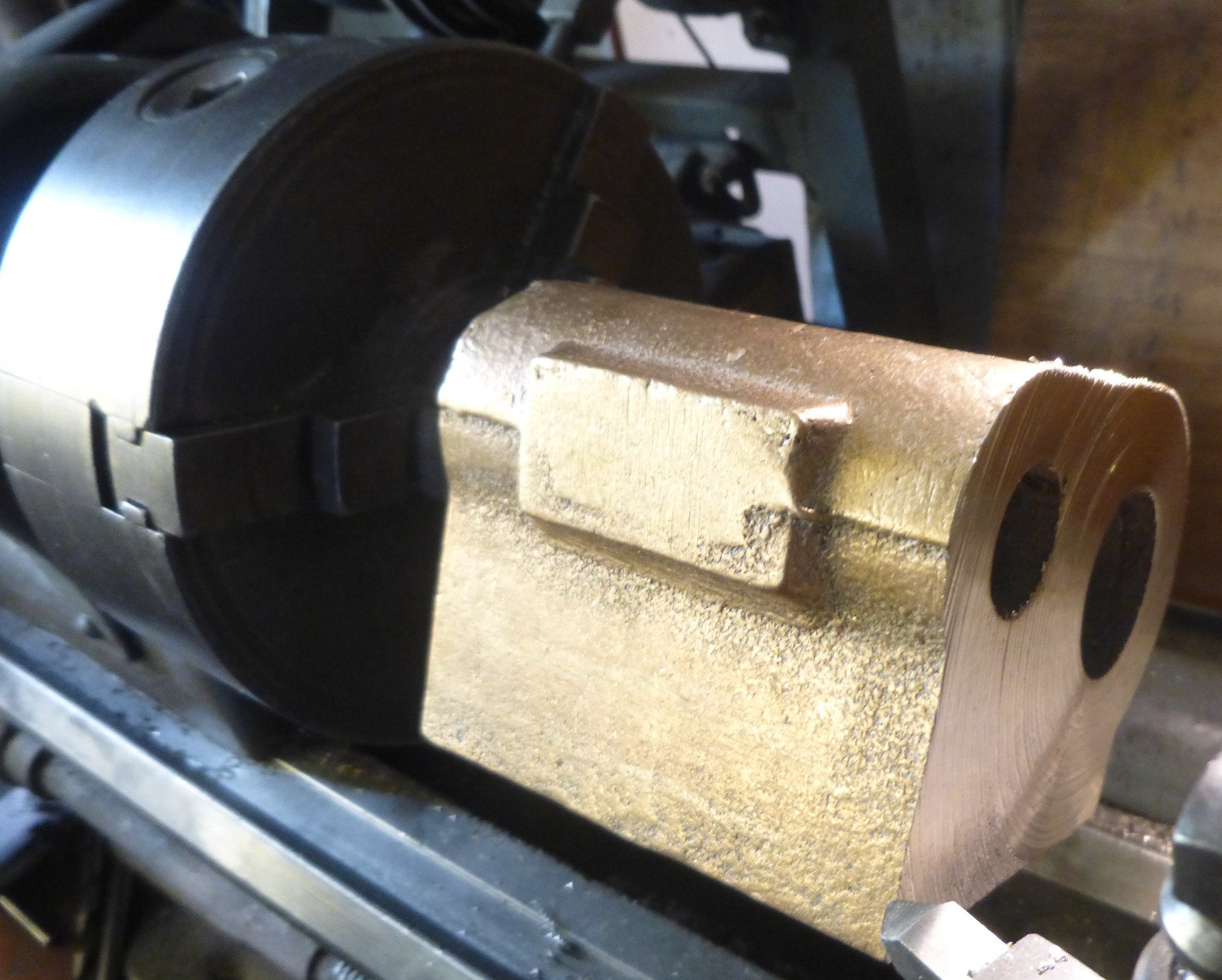 Facing in the lathe4 Facing in the lathe4 by Brian Leach, on Flickr 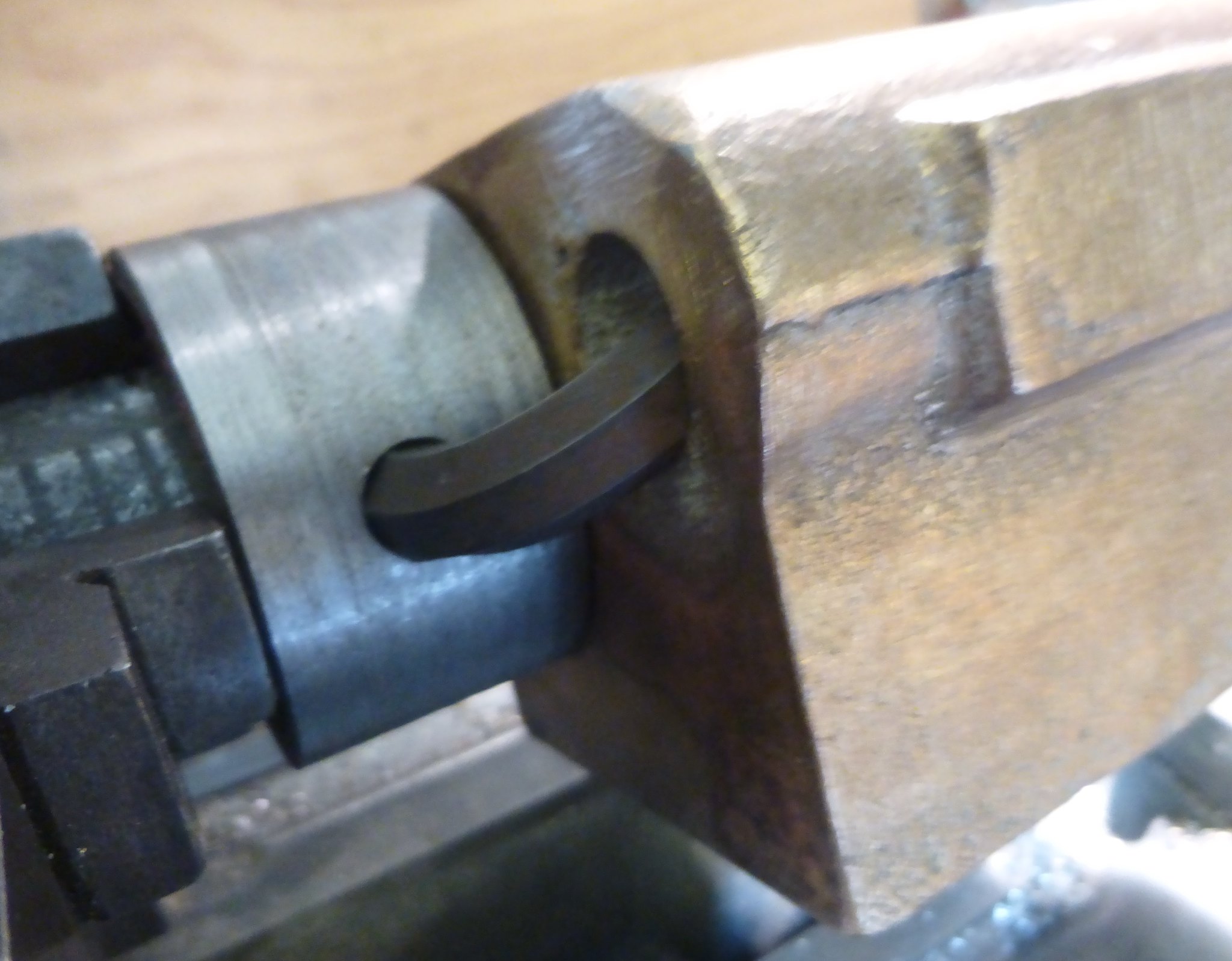 Facing in the lathe2 Facing in the lathe2 by Brian Leach, on Flickr 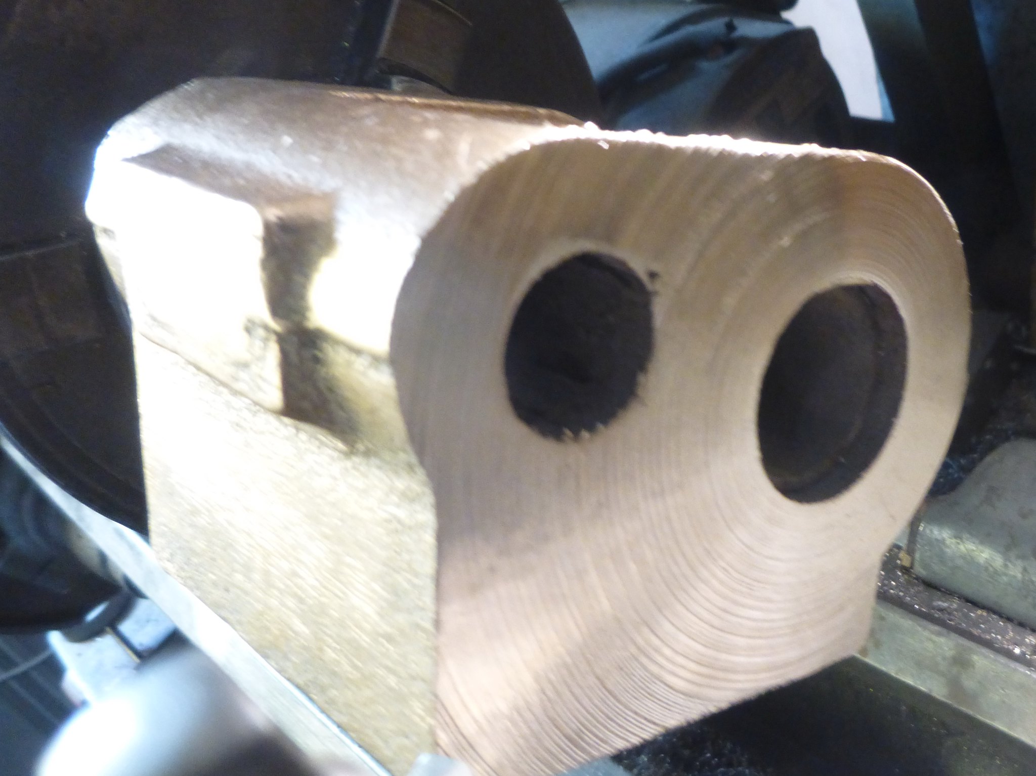 Facing in the lathe1 Facing in the lathe1 by Brian Leach, on Flickr |
|
JonL
Elder Statesman
   WWSME (Wiltshire)
Posts: 2,993
|
Post by JonL on Mar 21, 2019 6:54:50 GMT
I seem to have better results using HSS for finer stuff, but the carbide is great for getting through the skin on a casting. I think in my case a lot of it is technique, I'm getting better with them. For some things the versatility of being able to easily grind your own shaped edge is a bonus.
I say all of the above as a complete novice mind.
|
|
stevep
Elder Statesman
  
Posts: 1,073
|
Post by stevep on Mar 21, 2019 9:45:41 GMT
Brian, If I might offer some opinions on how to address your machining sequence. I see from the template that you offered up to the casting that the bores are 'off' from where they need to be. This is neither unusual nor a problem. I would use the milling machine to try and get the back, bolting face to the right position. Then I would clamp the casting to the lathe cross-slide, with the rear face to the headstock. The casting should be packed up to bring one of the bores to the right place (probably the piston one), and then I would use a tool in the lathe to face off the casting. I use a single point tool, mounted on a catch-plate. 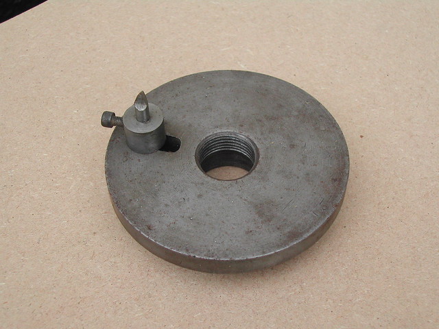 Then I would use a between centres boring bar to bring the bore to size. (I would actually use two - one that I would keep adjusting until the bore is close to size, and the second one which would be left un-touched, to do the final boring. This ensures the two bores are the same size). You might even have to use a third, much slimmer boring bar, until the bore has been cleaned up and is concentric to the final position. By doing it this way, you can be absolutely sure that the rear face - to which the slide-bars are ultimately connected, is dead square with the bore. The front face can then be cleaned up using the same process, with the casting turned through 180 degrees, after all the boring has been done. Even though I have a big, heavy milling machine, I think I would still do my cylinders this way. Steve |
|
|
|
Post by runner42 on Mar 21, 2019 22:32:24 GMT
Thanks Steve, excellent advice. I have a small problem with setting up the castings on the lathe's cross slide because being a Southbend it doesn't have the flat section with keyways similar to the bed on a milling machine, so I will have to make something to clamp the casting to. But part of ME is making jigs and fixtures.
Brian
|
|
|
|
Post by Roger on Mar 22, 2019 7:09:27 GMT
Thanks Steve, excellent advice. I have a small problem with setting up the castings on the lathe's cross slide because being a Southbend it doesn't have the flat section with keyways similar to the bed on a milling machine, so I will have to make something to clamp the casting to. But part of ME is making jigs and fixtures. Brian Hi Brian, I machined a flat on my Southbend lathe cross slide and added six M10 tapped holes on a grid so I could attach whatever I wanted to it. That's a very useful modification. |
|
JonL
Elder Statesman
   WWSME (Wiltshire)
Posts: 2,993
|
Post by JonL on Mar 22, 2019 10:18:25 GMT
...But part of ME is making jigs and fixtures. It's an interesting point; when I started I thought of the process of making jigs and such a bit of a pain, but now I enjoy it as much as the job in hand. |
|
|
|
Post by Roger on Mar 22, 2019 10:34:55 GMT
...But part of ME is making jigs and fixtures. It's an interesting point; when I started I thought of the process of making jigs and such a bit of a pain, but now I enjoy it as much as the job in hand. I couldn't agree more. I'd much rather spend an hour or more designing and making something to make the job quick and simple rather than work on a wing and a prayer, possibly scrapping the job in the process or ending up with a less accurate result. I've never regretted making a fixture, the same can't be said of the reverse! I can't understand the reluctance to engage with the whole process. Modifying tools and making these things is enormously satisfying and takes little more time in the long run, especially if you have more than one part to make, or can press a tool into use on more than one job. I always think about making something more general purpose with that in mind if at all possible. It's all part of making the piece, even though it's an indirect contribution. |
|
timb
Statesman
 
Posts: 512 
|
Post by timb on Mar 22, 2019 16:26:15 GMT
Hi Guys,
Just an observation but try to use 0 degree rake tools with rounded tips and a flat but short end cut angle(as for Brass) on GM. HSS is best in my experience and you should get a really smooth glass like finish. Give the cutting edge a rub on a diamond hone after the casting surface is removed.
Tim
|
|
|
|
Post by runner42 on Mar 23, 2019 5:06:30 GMT
Well following on from the jigs and fixtures comment I have started the fixture for boring between centres. It is basically a copy of the Southbend compound slide fixing which supports a flat plate for general applications similar to the boring between centres requirement. It shows the clamping for the flat section of the cross slide and where the cross slide casting tapers it has a couple of adjustable feet to keep the attachment level. The photo shows the basic setup and when tightening the cylinder casting clamp this caused the whole setup to turn so I had to add a spigot that locks it to the cross slide to prevent this occurring. This is just the beginning I am trying to understand how I would position the casting to commence the boring between centres' operation. The dilemma is what do I use as the reference? The bolting face could be used and the X distance from this could position the centre of the cylinder bore, alternatively I could find centre position of the cylinder bore and work back to establish the bolting face position. The first would be the most logical but because it isn't a Black 5 casting working this way would not necessarily position the centre of the bore so that it was sitting concentric with the casting outline and have equal distance all round. What do you suggest? Brian 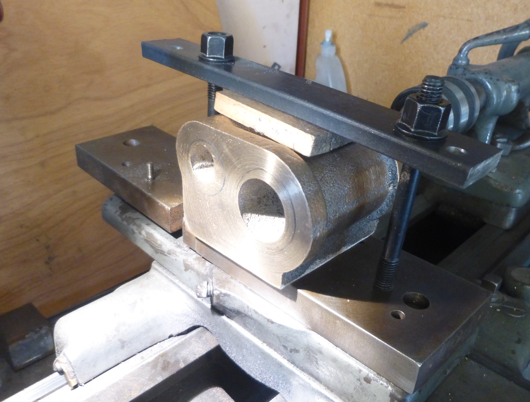 boring between centres setup1 boring between centres setup1 by Brian Leach, on Flickr 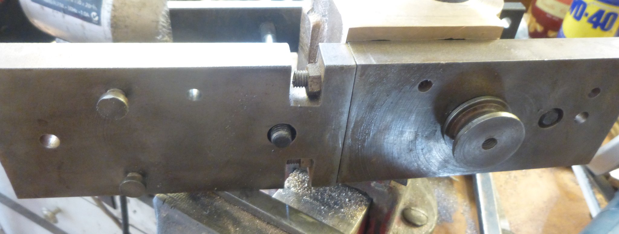 boring between centres setup3 boring between centres setup3 by Brian Leach, on Flickr 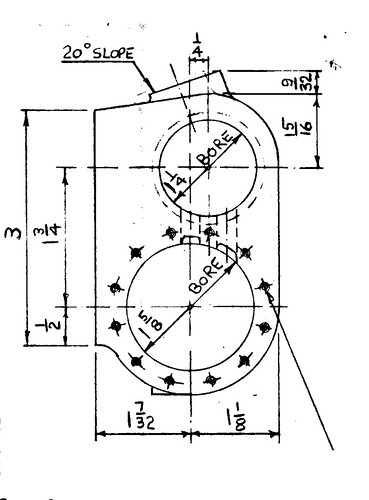 boring between centres setup4 boring between centres setup4 by Brian Leach, on Flickr |
|
|
|
Post by ettingtonliam on Mar 23, 2019 7:46:14 GMT
I strongly suggest that you plug the ends of the bores with wood, shaped roughly to fit, then tapped in. Then you can put cylinder bore centres where you think fits best, and generally play around marking the bores and bolting face till you think you've got the best fit. Then centre punch the bore ODs, and the edge of the bolting face and work off these, aiming to 'split the dots'. I'd machine the bolting face first, then you've got a true face to bolt down to, and you will know haw much packing you need to put under it.
|
|
|
|
Post by runner42 on Mar 25, 2019 6:25:27 GMT
Made wooden plugs for the cored holes and fiddled around with the marking out. It appears OK just as a rough guide, but I will have to think of ways of measuring the various dimensions. A height gauge and a surface plate would be ideal, which I don't have so it will have to be utilising what I currently have. When I finish tailoring the jig to holding the cylinders I intend to have the cylinder's bolting face at an angle of around 8 deg bringing the cylinder bore and piston valve bore in line so that I can machine both bores but still retain the same fixture. It will be just a simple operation to adjust the cross slide to the bring the bore centres to align with the lathe's axis. 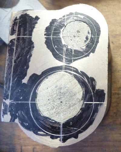 cylinder marking out cylinder marking out by Brian Leach, on Flickr I received the Driving and Driven wheels today after a long wait and was keen to start machining them. I was disappointed that they could not be machined even using carbide cutting tools, they contain many hard spots at the periphery. Sparks fly when I try to get under the casting skin. I don't know what to do to overcome this I will probably have to obtain a subcontract annealing and or machining service. Brian 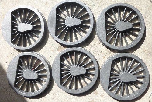 Driving and Driven Wheels Driving and Driven Wheels by Brian Leach, on Flickr 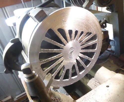 Driving Wheel machining Driving Wheel machining by Brian Leach, on Flickr |
|
JonL
Elder Statesman
   WWSME (Wiltshire)
Posts: 2,993
|
Post by JonL on Mar 25, 2019 6:41:29 GMT
That's disappointing. They look like quite nicely finished castings otherwise. Does the prototype have "straight edge" balance weights too?
|
|
|
|
Post by ettingtonliam on Mar 25, 2019 7:27:36 GMT
Sparks fly? What speed are you using? As low as possible, a decent carbide tool should get through any cast iron hard spots. If this doesn't work, do you have a wood burning stove, if so put them in the fire so they get up to red heat, then leave them overnight in the fire to cool down. That usually helps.
|
|
|
|
Post by runner42 on Mar 25, 2019 7:29:30 GMT
That's disappointing. They look like quite nicely finished castings otherwise. Does the prototype have "straight edge" balance weights too? No, similar to the cylinder castings these wheel castings are the right sized diameter but not a Black 5 casting. Brian |
|
|
|
Post by runner42 on Mar 26, 2019 7:30:50 GMT
I followed the advice to run the lathe at the slowest speed possible to machine the backs of the driving and driven wheels, this I did by engaging the back gear on the lathe. This however did improve the cutting on the centre hub and the periphery because the cutting tool is in constant contact with the wheel. However it was a totally hazardous and difficult process to machine the spokes because this was a series of interrupted cuts. The tool was being smacked to and fro with each interruption. The amount of metal I could remove at each pass was a few thou. I couldn't sustain that effort and gave up. This needs a different approach, so for the time being this task is put on the back burner. I went back to the cylinder boring and opted to use Steve (springcrocus) method of rough boring the cylinders by using a boring bar inserted into a square section and mounted in a 4 jaw chuck. But I didn't have a suitable boring bar, now on order but in the interim to use my boring head. Brian 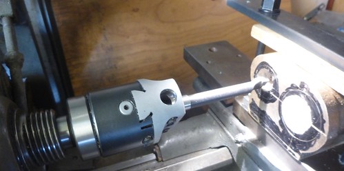 Rough boring in the lathe Rough boring in the lathe by Brian Leach, on Flickr |
|
|
|
Post by ettingtonliam on Mar 26, 2019 7:45:24 GMT
Depending on how much metal you have to remove from the backs of your wheels, you could take a pass over with an angle grinder, see if that gets the skin off. I'm not a huge fan of replaceable tip tools, at least for the initial cuts on iron castings. I find the older brazed tip carbide tools perform better on this work, and no I don't mean the cheap chinese ones. The tool being smacked too and fro doesn't sound right at all. What is the lowest speed you have available? Still leaves you the option to anneal them as I described earlier. I suppose having waited so long for these wheels you don't feel like sending them back and demanding some decent ones? You should complain anyway, see what your supplier says.
|
|
|
|
Post by Roger on Mar 26, 2019 8:54:36 GMT
I followed the advice to run the lathe at the slowest speed possible to machine the backs of the driving and driven wheels, this I did by engaging the back gear on the lathe. This however did improve the cutting on the centre hub and the periphery because the cutting tool is in constant contact with the wheel. However it was a totally hazardous and difficult process to machine the spokes because this was a series of interrupted cuts. The tool was being smacked to and fro with each interruption. The amount of metal I could remove at each pass was a few thou. I couldn't sustain that effort and gave up. This needs a different approach, so for the time being this task is put on the back burner. Hi Brian, It sounds like the setup isn't rigid enough and the speed is still probably too high. Intermittent cuts aren't usually a problem if you reduce the overhangs to the absolute minimum and use the biggest carbide insert holder that will fit the tool post. My parting/grooving tool was slightly too big for my tool post, so I machined a couple of millimetres off the bottom so it would fit rather than use a smaller one. A few thou in a pass is fine, it doesn't matter if it takes a long time, especially if you have power feed. Locking the carriage can help with the rigidity and also stop it being pushed away by the cutting forces which can be a problem. On the issue of speed, this is another reason why variable speed drives are so useful. Not only do they allow you to slow down the RPM, but they also reduce the torque which is usually way more than you need or want for this sort of work. There are some situations where in old school books they tell you to pull the belt by hand, a clear admission that the lathe can't be driven slowly enough. Usually the issue they are trying to avoid is chatter. So for a final finishing cut, you can always do it that way. It's slow, but it does work. |
|
|
|
Post by ettingtonliam on Mar 26, 2019 11:28:26 GMT
Looking again at the photo of the wheel turning operation, I tend to agree with Roger's comments about rigidity. Those lantern toolposts are not the most rigid in the world, so you should get the tool overhang down to an absolute minimum, speed as low as possible, 50 rpm or less, 25 if you can and try again. You shouldn't let the tool rub, try a decent cut to get under what is hopefully only a hard skin. Then there is the subject of the grade of tip you are using, is it recommended as suitable for cast iron?
Are all the wheels just as bad?
|
|
|
|
Post by Deleted on Mar 26, 2019 11:51:48 GMT
I followed the advice to run the lathe at the slowest speed possible to machine the backs of the driving and driven wheels, this I did by engaging the back gear on the lathe. This however did improve the cutting on the centre hub and the periphery because the cutting tool is in constant contact with the wheel. However it was a totally hazardous and difficult process to machine the spokes because this was a series of interrupted cuts. The tool was being smacked to and fro with each interruption. The amount of metal I could remove at each pass was a few thou. I couldn't sustain that effort and gave up. This needs a different approach, so for the time being this task is put on the back burner. I went back to the cylinder boring and opted to use Steve (springcrocus) method of rough boring the cylinders by using a boring bar inserted into a square section and mounted in a 4 jaw chuck. But I didn't have a suitable boring bar, now on order but in the interim to use my boring head. Brian  Rough boring in the lathe Rough boring in the lathe by Brian Leach, on Flickr Hi Brian I really don't like that idea with the boring head, especially as you say the lathe has a high low speed, I would stick to a 'between centre's' boring bar. These are easy to make with a suitable length of steel, centre drilled deeply each end and cross-drilled to accept whichever size tool steel you wish to use. Use the largest dia steel that can fit in the bores as they are, you may need a second larger boring bar to finish. I find the chuck is good enough for the headstock end but others prefer another centre with dog drive. Pete |
|


