uuu
Elder Statesman
 your message here...
Posts: 2,809
|
Post by uuu on May 1, 2020 12:28:48 GMT
I don't see a slot. I interpret the 1/2" as being the spacing of the top fixing holes. If there were a slot, you'd not have 8 bearing fixing holes.
Wilf
|
|
|
|
Post by Deleted on May 1, 2020 13:22:38 GMT
The slot wouldn't work as drawn due to the placement of the bearing bolts.. in the first reply I had written up about doing a slot and clocking the bearing mounts by 45 degrees but deleted it as it was getting too long....I'm sure that Brian will sort it, as the saying goes 'there are many ways to skin a cat'.
Pete
|
|
don9f
Statesman
 Les Warnett 9F, Martin Evans “Jinty”, a part built “Austin 7” and now a part built Springbok B1.
Posts: 960 
|
Post by don9f on May 1, 2020 23:05:34 GMT
Hi, whilst the idea in the post by d304 is quite feasible, I thought the 1/2 inch dimension referred to the hole spacings....ie 4 holes 1/2 inch apart. I am pretty certain that the bearings will be “blind” as Pete said and fitted from the outside, projecting through the 13/32 holes somewhat as this follows the full size arrangement. Also I would have expected the brakeshaft assembly to be finished as one piece, but the other ideas about a separate 9/32 “shaft” could also work.
What are the dimensions of the bearings, as they could determine if Don has incorrectly drawn the lengths of the 9/32 dia. parts of the shaft?
Cheers Don
|
|
|
|
Post by runner42 on May 2, 2020 0:22:24 GMT
Thanks for the replies. The brake shaft bearings holes are not blind, I had already made the brake shaft assembly and found that it could not be rotated to enter one trunnion hole and then straightened to enter the other trunnion hole. The trunnion holes are two small to get the required rotation, Wilf's drawing I think demonstrates this. The shaft could be reduced to enable it to be assembled in the manner stated but it would reduce the amount of shaft held in the bearing. Don Young doesn't appear to state how assembly is achieved, it assumed it to be axiomatic, but he states that the whole brake shaft assembly is silver soldered, so no suggestion that the shaft be left separate. What I am going to do is make the shaft in two pieces, in line screwed together. One piece is going to be of a length to include the actuating hub and extend to the outside of one bearing and the other of a length to cover the remaining bearing. With the reduced shaft length I will be able to install it in the trunnion and then screw the stub shaft into the brake shaft assembly. The bearings then installed as per drawing. Brian  brake shaft bearing brake shaft bearing by Brian Leach, on Flickr |
|
don9f
Statesman
Les Warnett 9F, Martin Evans “Jinty”, a part built “Austin 7” and now a part built Springbok B1.
Posts: 960
|
Post by don9f on May 2, 2020 8:22:40 GMT
Right well the 11/32 lengths of the two 9/32 dias, plus the other brakeshaft and bearing dimensions confirm that the assembled parts would all look right, it’s just that it definitely cannot be assembled! Your solution is a good one.
Cheers Don
|
|
nonort
Part of the e-furniture
If all the worlds a Stage someone's nicked the Horses
Posts: 277
|
Post by nonort on May 2, 2020 9:44:14 GMT
Could it be that like LBSC's Britannia expansion brackets that you can't assemble as drawn. That you could chamfer one of the holes on the inside edge to allow the shaft the twist more. The removal of this metal won't make a figs worth of difference to the strength of the bracket. You could even slot the the bracket without it making any real difference to the bracket strength. Unless you run someone over with the loco no one will ever see it.
|
|
|
|
Post by d304 on May 2, 2020 10:36:03 GMT
Two ideas. Use my way of the slot on one side and use the bearings. The bearing on the slot side will have the bottom hole drilled and tapped for 10 BA for a cosmetic bolt.
Alternative 2 is to have blind bearings. The fabrication would be able to spin on the shaft which is held in place by the bearings and easy to assemble.
Brian, have you tried a quick rough mock up of the brake shaft and see will it wiggle through.
regards
David
|
|
44767
Statesman
Posts: 529
|
Post by 44767 on May 3, 2020 15:16:28 GMT
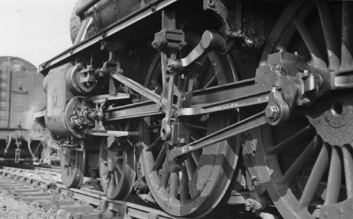
I have to put you all out of your misery! Don's design doesn't work, as you have demonstrated. I must have had the same problem when I built my model. I made most of my parts with reference to photographs of the full size. I would make the overall and important dimensions to the drawing but add detail if I thought it were necessary. So, for this part, I noticed that the full size one is not a welded fabrication, it is bolted together. Another detail that I included in my model is that the bushes are held in by five bolts, not the four shown on the drawing. Here's a random view under 44767 which shows the bracket.  Here's a pic that I have just taken of mine.  If you've already made yours as a soldered fabrication, I would look at making the holes for the bushes a diameter that would allow the shaft to feed in to position and make bushes to suit. Cheers,Mike |
|
oldnorton
Statesman
5" gauge LMS enthusiast
Posts: 693
|
Post by oldnorton on May 3, 2020 21:50:17 GMT
Make a separate shaft that slides in to support the crank lever and locate it with blind bushes.
|
|
|
|
Post by runner42 on May 4, 2020 7:45:56 GMT
Some novel suggestions and confirmation that Don Young's drawing is a bit off and another indication that he didn't build a Black 5. However, I went ahead with my proposal of making the shaft in two pieces and screwed together. The pictures show the bits with a temporary assembly. I had little wiggle room when installing the rod carrying the return spring not shown in the photos. But everything is now finally assembled and now waiting for the tender wheels to arrive, hopefully this week to finish the tender chassis. Brian  Steam Brake trunnion and shaft Steam Brake trunnion and shaft by Brian Leach, on Flickr  Steam Brake assembly Steam Brake assembly by Brian Leach, on Flickr |
|
|
|
Post by coniston on May 4, 2020 19:36:30 GMT
Nice one Brian, I'm sure that's an excellent solution.
Chris D
|
|
|
|
Post by runner42 on May 7, 2020 22:34:19 GMT
Whoopee! Received the tender wheels after 5 months wait, but the look very good and unlike the locomotives driving and driven wheels these have been tempered so machining is going to be like cutting butter and can use HSS tools. Brian  tender wheels tender wheels by Brian Leach, on Flickr |
|
|
|
Post by steamer5 on May 7, 2020 22:43:04 GMT
Hi Brian,
So how did they temper them? 5 months under the bench wouldn’t be enough!
I’ve had mine sitting under the bench of 18 years, I’m thinking that they may just about be ready.
Cheers Kerrin
|
|
|
|
Post by runner42 on May 8, 2020 7:18:10 GMT
Hi Brian, So how did they temper them? 5 months under the bench wouldn’t be enough! I’ve had mine sitting under the bench of 18 years, I’m thinking that they may just about be ready. Cheers Kerrin Hi Kerrin, they were heat treated, ie heated to the required temperature and allowed to cool very slowly. I didn't know that a prolonged elapsed time could produce the same result. Waiting 18 years is being very patient, returning them is out of the question now so I hope for your sake that they are easily machined. Brian |
|
|
|
Post by ettingtonliam on May 8, 2020 8:08:48 GMT
Waiting won't soften cast iron. When time wasn't so important, castings were left outside in the weather to 'season' This allowed residual stresses to settle out, and the rusting tended to lift off casting sand from the surface.
Over the years I haven't often had issues with hardness in castings, but those which I did, I put in the fire towards the end of the evening, and left them overnight to cool in the ashes. That usually did the trick.
|
|
|
|
Post by delaplume on May 8, 2020 15:29:21 GMT
Hello Brian,
I think if anything you might come across a hard spot or a small void (pocket) .... Unlikely in this day and age of quality controll but it can happen....like so}-----
A few years ago I ordered a set of GWR Star / Castle castings for my Great Bear project from a well-known Model Engineer main supplier ( It doesn't matter who... it's just the experience I wish to illustrate )....
During machining an inclusion was encountered within the main steam chest area......It was "Glass-hard" and deflected the tool no matter how small a cut was used...... As it was partly within the piston valve liner area it had to be machined, or replaced..
After informing the supplier -- and the inevitable lost time due to arguments, correspondence etc.... a replacement casting was forthcoming.
If you can I'd use carbide tools / tips --- Nowadays they are in plentiful supply and numerous profiles to suit most needs...
|
|
|
|
Post by ettingtonliam on May 8, 2020 19:04:11 GMT
The biggest enemy to successful machining of iron castings is speed. The traditional cutting speed is 50 feet per second, which, for an 8" dia wheel means something between 25 and 30 rpm. OK, thats for high speed steel, but even with carbide tooling, it probably shouldn't be more than about 50 rpm to start with. The other essential is to make the first cut a decent one, to get under the'skin' of the casting. I light cut where the tool rubs is fatal, you'll loose the edge of the tool in a few seconds.
I had a hard spot incident years ago when I was machining the trunk guide casting for a 4" scale traction engine. The main bore and flange was fine, but when I came to drill out for the weighshaft bearings, there was a dreadful hard spot, which just deflected any HSS tooling (this was before the ready availability of carbide drills and endmills). I was doing it in evening class at Dewsbury Tech, and the technician told me to make a D bit from silver steel, harden it but not to temper it, then use it at very low speed. I did, and it worked!
Some of the fullsize traction engine makers used to use a 'chill' when casting cylinders so the bore was really hard to resist wear. How they managed the machining I don't know, but however they did it, all they had was carbon steel tooling, even HSS wasn't available to them.
|
|
|
|
Post by Roger on May 8, 2020 20:34:45 GMT
The biggest enemy to successful machining of iron castings is speed. The traditional cutting speed is 50 feet per second, which, for an 8" dia wheel means something between 25 and 30 rpm. OK, thats for high speed steel, but even with carbide tooling, it probably shouldn't be more than about 50 rpm to start with. The other essential is to make the first cut a decent one, to get under the'skin' of the casting. I light cut where the tool rubs is fatal, you'll loose the edge of the tool in a few seconds. I had a hard spot incident years ago when I was machining the trunk guide casting for a 4" scale traction engine. The main bore and flange was fine, but when I came to drill out for the weighshaft bearings, there was a dreadful hard spot, which just deflected any HSS tooling (this was before the ready availability of carbide drills and endmills). I was doing it in evening class at Dewsbury Tech, and the technician told me to make a D bit from silver steel, harden it but not to temper it, then use it at very low speed. I did, and it worked! Some of the fullsize traction engine makers used to use a 'chill' when casting cylinders so the bore was really hard to resist wear. How they managed the machining I don't know, but however they did it, all they had was carbon steel tooling, even HSS wasn't available to them. These days I think it's fair to say that Indexable Carbide inserts will cope with anything that Cast Iron can throw at them. The first generation of Carbide, Brazed to a holder was nowhere near as tough as the ones on sale today. Although in principle it sounds plausible to get under the skin with the first cut, the reality is rather different. You're almost certainly going to get intermittent cuts and some places where it's going to be very light cuts. Inserts don't have any trouble this this in my experience. I only use HSS when I want to grind a shape onto the tool that isn't available in an insert. There's a good reason why they use Carbide in industry. |
|
|
|
Post by steamer5 on May 9, 2020 4:10:34 GMT
Hi Brian,
Sorry for putting your post on a side track! My comment was more than a little tongue in cheek.
I always knew my castings were going to be under the bench for awhile, I was lucky that my Dad came across a guy, from Australia as it happens, who was at the NZ Model Engineer Convention & in discussion Dad found out that he was building a K1 & got his contact details. At the time the guy had just about finished all the patterns, well the vast majority of them, so once they were proven I jumped at the chance to get a set. So I now have in excess of 50 kgs (I’ve not weighed the whole lot but each LP cylinder is currently 11plus kg, & that’s with piston & valve bores cored!) of casting sitting under the bench waiting......quite a bit longer than I had thought!
I’m very hopeful that there aren’t any hard spots as we don’t have an open fire.
Cheers Kerrin
|
|
|
|
Post by ettingtonliam on May 9, 2020 6:47:00 GMT
As Roger says, there shouldn't be anything that modern carbide tooling can't deal with. Visually, hard spots can show as a shiny patch on the finished article, but K1 is outside framed isn't it, so the wheels don't show much?
|
|