mbrown
Elder Statesman
  
Posts: 1,790
|
Post by mbrown on Jan 3, 2021 21:37:44 GMT
There are still a number of bits to add to the frames before they can be erected - today's job was the brake hanger brackets. The prototype is braked on the first and third axles only, which means there are four brake hangers. The holes in the frames had been drilled already using a jig (a slab of 1/4" BMS located by two other holes already in the frame). I used the same jig to drill the backs of the brackets. The brackets themselves were made from 3/4" dia BMS - this is just too big to go through the Myford spindle and, as I hadn't much material to spare, I made them in pairs back to back so that one could be the chucking piece for the other. There they are before parting off and facing to length.  IMG_20210103_150009 IMG_20210103_150009 by malcolm brown, on Flickr Each one then had a 6 BA threaded hole put in the centre of the back. This was used to screw the part to the jig which had been used to drill the frames so that the three holes could be spotted through to match. Here's one mounted on the jig.  IMG_20210103_160212 IMG_20210103_160212 by malcolm brown, on Flickr To make the backs triangular, as on the real thing, I put 8 BA cheesehead screws into two of the holes and used them with a spacer to set the piece level in the machine vice. It was then easy to do all the sides at the same setting. 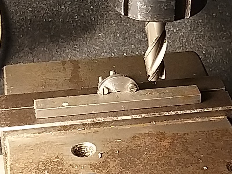 IMG_20210103_162134 IMG_20210103_162134 by malcolm brown, on Flickr With the corners rounded off with a file, here they are. The triangles are not equilateral as the bolt holes are used to fix bits on the other side of the frames - again, as on the prototype.  IMG_20210103_171346 IMG_20210103_171346 by malcolm brown, on Flickr Best wishes Malcolm |
|
mbrown
Elder Statesman
  
Posts: 1,790
|
Post by mbrown on Jan 10, 2021 18:20:15 GMT
Finishing the frame stretchers has taken ages, but it was all much of a muchness, so no point posting photos. Only a couple of tricky ones left to do, and those need fitting to place. So, at last, I am at the point where the frames can be erected. For this, I decided to approach it the way I have seen it done in pictures of the old railway workshops - holding the frames the right distance apart with turned spacers and long bolts and resting on a true surface.  IMG_20210110_170849 IMG_20210110_170849 by malcolm brown, on Flickr I found three places where existing holes, of various diameters, could be utilised. The spacer at the rear is from square tubing as it just accommodates the four 10 BA nuts which secure the brake shaft bearings. It took ages to get everything truly square in every direction, but this method means that it is possible to tighten everything up firmly before starting to drill for fixing bolts. So much less chance of anything going awry. Here it is the other (right) way up.  IMG_20210110_170927 IMG_20210110_170927 by malcolm brown, on Flickr The assembly is too large to line up on the lathe bed so I am using a length of laminated kitchen worktop which seems very flat. As well as the trusty engineer's square, I am double checking things like the corner to corner dimensions, so that I can be absolutely certain everything is true before bolting it all together. That in itself will take a fair while, I suspect.... Cheers Malcolm |
|
mbrown
Elder Statesman
  
Posts: 1,790
|
Post by mbrown on Jan 16, 2021 22:07:00 GMT
This weekend, the frame erection continues.... The front and rear buffer beams went on quite quickly and then the cross stays which form the front and back of a box between the cylinders.  IMG_20210116_175656 IMG_20210116_175656 by malcolm brown, on Flickr I have checked, and the pump can be wangled in and out of its mounting on the front stretcher without too much difficulty. The bottom of the box is a horizontal stretcher which ties together the buffer beam and the two vertical stretchers. Because I am too big to get my head and arms through the openings to reach the cylinder mounting bolts, it will have to be removable, and as the upper side of it is inaccessible too, I needed to tap the angles and use screws to fix it. On the prototype, the horizontal stretcher is fixed with rivets with shallow domed heads and I am trying to replicate that with 8 BA raised countersunk screws. I may fill the slots when the whole thing is finished and painted, but as no one will see any of this without turning the loco upside down, I may just leave them. Looked at from a low angle, the heads should just be visible as the rivets are in full size.  IMG_20210116_175729 IMG_20210116_175729 by malcolm brown, on Flickr Some of the intermediate stays are seen beside the frames. They may get assembled tomorrow when I have done the rear end horizontal stretcher. However, I anticipate a problem there as I drilled the fixing holes in the frame before deciding to make the stretcher of thicker material (because it takes all the drawbar forces) and I suspect the holes will pierce the fixing angle so close to the web that I won't be able to fit nuts as planned. We'll see. But if that does happen, I have a cunning plan (although it will slow down assembly. More soon. Malcolm |
|
JonL
Elder Statesman
   WWSME (Wiltshire)
Posts: 2,990
|
Post by JonL on Jan 16, 2021 22:48:24 GMT
Lovely work, very neat.
|
|
|
|
Post by steamer5 on Jan 17, 2021 2:38:35 GMT
Hi Malcolm,
Coming on very nicely!
On the screw front have you checked out button head cap screws? They might just give you the rivet look you are after & given we’re they are you probable won’t see the hexhole in the head.
Cheers Kerrin
|
|
mbrown
Elder Statesman
  
Posts: 1,790
|
Post by mbrown on Jan 17, 2021 11:14:56 GMT
Thanks Kerrin - that would have been an excellent solution... if I had thought of it in time!
I don't think button headed cap screws are available in 8 BA (at least I can't find any) but there are 2mm and 2.5mm ones out there. However, as I have countersunk the holes and tapped the angles, it's too late now. One to think about for another time.
Best wishes
Malcolm
|
|
|
|
Post by norfolkandgood on Jan 17, 2021 13:31:08 GMT
Very nice work.
|
|
barlowworks
Statesman
  Now finished my other projects, Britannia here I come
Posts: 878 
|
Post by barlowworks on Jan 17, 2021 15:47:36 GMT
EKP supplies 8ba roundhead screws, no slots.
Mike
|
|
mbrown
Elder Statesman
  
Posts: 1,790
|
Post by mbrown on Jan 17, 2021 16:38:21 GMT
Thanks. I am using a lot of those. But you can't put them in from one side - there's no traction on the head so they need nutting from behind.
I am actually wrestling with some EKP slotless 8BA screws (and nuts) right now!
Malcolm
|
|
mbrown
Elder Statesman
  
Posts: 1,790
|
Post by mbrown on Jan 17, 2021 21:08:33 GMT
Talking of slot-less round headed screws.... I have been using a lot of EKP's 8BA slot-less screws as the heads are about the right size for many of the rivets on the loco and tender frames of 99 3462. But for some applications they are rather too large - and I don't know of anyone doing smaller roundhead screws without slots. So I did a bit of experimenting. Ages ago, I made a small fixture to use in the lathe to shorten small screws. Basically, It's just a 1/4" threaded spigot and a nut with a small hole at the end to take a screw. You put the screw into the nut, tighten it onto the spigot, and can then work on the protruding end. It's not an original idea - I picked it up from an old issue of ME, I think. I have made nuts to suit 12, 10 and 8 BA screws.  IMG_20210117_152930 IMG_20210117_152930 by malcolm brown, on Flickr I found that I could use it to hold 5/64" rivets tightly enough to put an 8BA thread on the end.  IMG_20210117_153115 IMG_20210117_153115 by malcolm brown, on Flickr The rivet is a bit undersize for 8 BA, but what matters is that part of the stem can be left unthreaded and the hole is drilled to suit. It then acts as a bolt rather than a set screw. I haven't done many yet - it is a job for when I am in the right mood for repetition work - but each one was very easy to do. 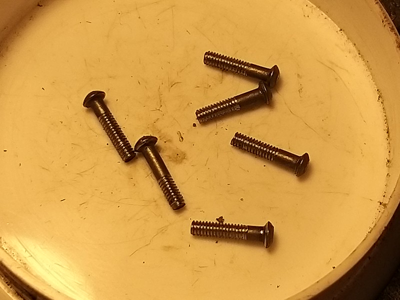 IMG_20210117_153806 IMG_20210117_153806 by malcolm brown, on Flickr It is certainly quicker and easier than turning the heads on the slot less screws to a smaller profile. Malcolm |
|
mbrown
Elder Statesman
  
Posts: 1,790
|
Post by mbrown on Jan 17, 2021 21:21:17 GMT
As I feared, the use of 2.5 mm instead of 1.5 mm plate for the rear horizontal stay meant that the fixing screws came too near to the web of the angles to be able to fit nuts. As the screws were slot-less 8 BA roundheads, I had to use nuts and couldn't drive them into tapped holes. So off came the angles. This was fairly easy to do without damaging them - I filed a small flat on the head of each rivet which made it easy to centre pop it centrally. I then drilled into the head at a fraction under the rivet diameter to just below the level of the head. A tap with a small cold chisel took the heads off easily, and then the shank drove out without much persuasion using a 1/16" punch. Instead of the angles, I silver soldered lengths of 1/4" x 1/8" BMS to the edges and put in some countersunk dummy rivets to fill the holes and give the right appearance from below. That left just enough room to bolt the stretcher in place as originally planned. Here it is from on top:  IMG_20210117_175733 IMG_20210117_175733 by malcolm brown, on Flickr It also shows the small vertical stretcher to which it is attached. And here it is from beneath - which is the more interesting view! It shows how the stretcher attaches to the buffer beam via the brackets for the safety chains which were made months ago at the same time as the ones for the tender - as was the coupler pocket, also attached.  IMG_20210117_175750 IMG_20210117_175750 by malcolm brown, on Flickr One of the other vertical stretchers has gone in too - it uses the bolts which also hold the equaliser pivot pockets to the outside of the frame. And finally, the acid test - the brake shaft, which is a close fit in the reamed bushes, slides in nicely and rotates freely. Evidence, I hope, that the frames are true and square in every plane.  IMG_20210117_183745 IMG_20210117_183745 by malcolm brown, on Flickr There are still a lot of bits to assemble between the frames, but it is getting there. Best wishes Malcolm |
|
|
|
Post by coniston on Jan 17, 2021 22:06:39 GMT
Excellent work Malcolm, when you see it assembled like that you can really appreciate the amount of work involved in making such a wonderfully scale loco, and to your own design
Chris D
|
|
mbrown
Elder Statesman
  
Posts: 1,790
|
Post by mbrown on Jan 24, 2021 21:19:08 GMT
Two lengthy sessions in the workshop this weekend have seen the erection of the frames almost completed - albeit at the cost of several 8 BA (9 BA Hex) nuts dropped on the floor from cold fingers.... The prototype has a rather interesting stretcher under the ashpan - leading forward from the rear cross member alongside the frames, sculpted to fit around the brake shaft bearings then turned up to mate with another shallow cross member immediately in rear of the fourth set of wheels. Here is a picture taken from the pit - you can see the brake shaft going across and the ashpan above. This is a view of the RH frame with the rear of the loco to the right. You can just see the steam brake cylinder through the inspection hole in the frame. With no pit in the WEM's loco shed, only in the workshops, it is no wonder it doesn't get cleaned around there very often....  DSC00512 DSC00512 by malcolm brown, on Flickr I had the basic "three sides of a square" water jet cut with the last order, and it was straightforward to shape it to match the frame profile and meet the shallow cross stay. For fixing to the frame, I silver soldered small pieces of plate into the corners which gives added reinforcement. This was easy enough, standing each leg in turn on the hearth, the bent up ends keeping it all square.  IMG_20210124_170208 IMG_20210124_170208 by malcolm brown, on Flickr Meanwhile, between the frames, all the cross members between the rear of the cylinders and the front of the firebox are tied together with a longitudinal horizontal stay, strengthened with angles along each side. All this assembly has now been installed. Here it is looking forward (some of the bolts need trimming back a bit...):  IMG_20210124_183128 IMG_20210124_183128 by malcolm brown, on Flickr And, looking at it from below, you can see the rear horizontal stay in place - although I ran out of time before I could bolt it in.  IMG_20210124_183113 IMG_20210124_183113 by malcolm brown, on Flickr I must be crazy as none of this work between the frames will be visible unless the loco is turned upside down - and then most of it will be hidden, as I found when in the pit under the real thing.... I am also having to remind myself that every single bit of this will be painted bright red in true German style. I will soon have to think what to tackle next... Best wishes Malcolm |
|
mbrown
Elder Statesman
  
Posts: 1,790
|
Post by mbrown on Jan 30, 2021 22:17:51 GMT
Most of today's workshop time has been spent fitting the final stretcher into the mainframes as in the previous post. Fiddly and tedious, but all done now. I am seriously weary of 8 BA nuts and bolts and 5/64" rivets - I have lost count of the number involved in these frames but it is well into three figures for each. Nevertheless, while I have all the relevant tools out, it seemed sensible to revisit the tender chassis one more time. I have never been completely happy with the rear tender buffer beam. It was one of my very early CAD drawings and I hadn't quite mastered complex curves. Here is the beam as I drew it and received it back from MEL...  IMG_20210130_173137 IMG_20210130_173137 by malcolm brown, on Flickr And here is the original which is significantly more... well - "voluptuous" in its curves.... 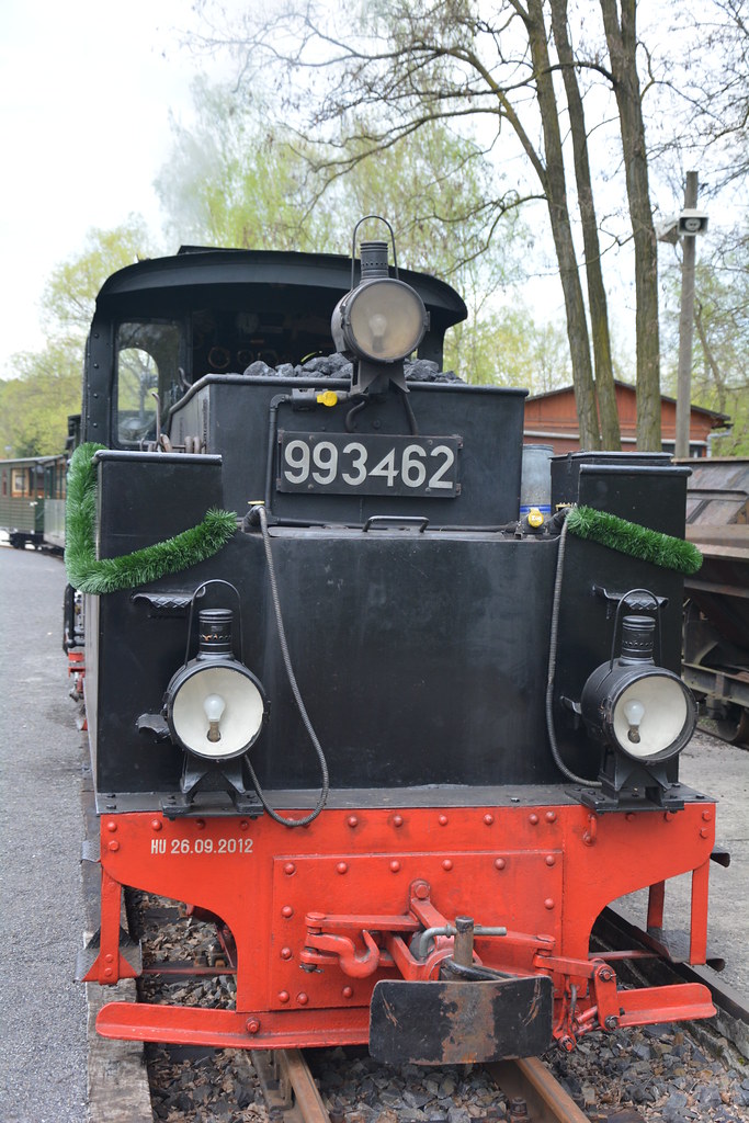 Bad_Muskauer_Bahn_BR_99_3462..005 Bad_Muskauer_Bahn_BR_99_3462..005 by malcolm brown, on Flickr So, a while ago, I redid the drawing and a new buffer beam came in the batch of waterjet cut parts received from GS Models before Christmas. Today, I have managed to unbolt the old beam and knock out the rivets. Tomorrow's job is drilling the new beam and reassembling it again. Best wishes Malcolm |
|
mbrown
Elder Statesman
  
Posts: 1,790
|
Post by mbrown on Jan 31, 2021 21:38:14 GMT
And here's the finished job for comparison with the photos above. The variation in the profile is not huge, but I think it makes a big difference and it won't now nag at me every time I se it!  IMG_20210131_181623 IMG_20210131_181623 by malcolm brown, on Flickr Making a new doubler plate to go with the new buffer beam enabled me to set the height of the buffer-coupling at the correct position for the loco in DR days rather than the lower position it gained in preservation to go with the altered buffer and draw gear. I have also added the angle which runs beneath the buffer beam - not sure what to call it... guard iron? Cow catcher? bumper?? I used the old buffer beam as a template to drill the new one. In order to make sure the angles for fixing to the frame were accurate and firmly rivetted, I opened the holes out to 3/32" and used the larger rivets, but with the heads turned down to match the old ones and the others on the beam. This was actually not "turning" exactly but done very quickly by eye using a file in the lathe. The pressure of the rivet sett ensured all the heads were true. In other news, as they say. the steam brake cylinder is now mounted - you can just see the thin doubler plate behind it which makes up the difference in thickness between the frame and the angle above. There is one just like it on the prototype. And the pump is mounted at the front between the cylinders. The drive will be from an eccentric on the front axle with the rod passing through the opening (again, as per prototype) in the vertical stretcher behind the cylinders. 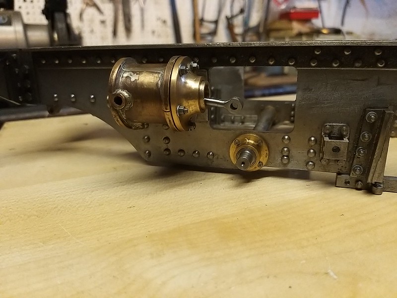 IMG_20210131_181706 IMG_20210131_181706 by malcolm brown, on Flickr 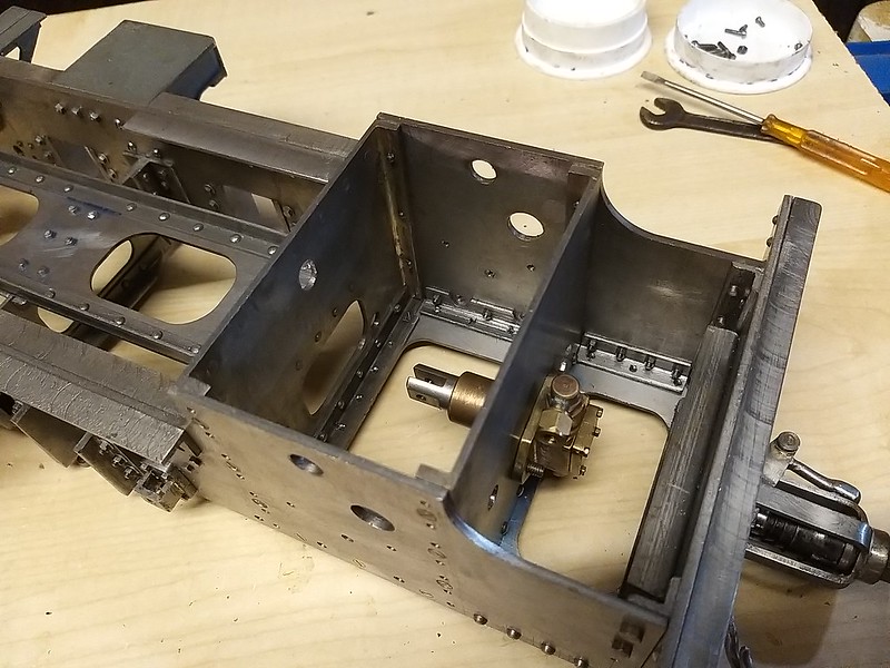 IMG_20210131_181753 IMG_20210131_181753 by malcolm brown, on Flickr I am now spoilt for choice in terms of what to make next. The steam brake cylinder and brake rod are crying out to be coupled together, so maybe the brake levers - or possibly the steam and exhaust pipework. More soon, anyway... Best wishes Malcolm |
|
mbrown
Elder Statesman
  
Posts: 1,790
|
Post by mbrown on Feb 4, 2021 11:02:04 GMT
A quick question.....
I have the leaves for my springs cut from spring steel and will need to silver solder a short bar on each end of the top leaves to take the spring pin bearing.
Don Young suggests that the way to silver solder things like this without losing the temper of the spring steel is to stick the main part of the leaf in a large potato leaving just the bit to be soldered visible.
Has anyone tried this, and does it work OK?
If so, I shall have to beg borrow or steal a large spud - but I won't go raiding the pantry if there are better ways of tackling the problem.
Thanks
Malcolm
|
|
|
|
Post by Deleted on Feb 4, 2021 17:50:27 GMT
Hi Malcolm yes, it does work, gives off a lovely smell of baked potatoes too..  I think that I posted a picture of when I did my tender springs...I pushed the spring leaf all the way into the spud just leaving exposed the part that needed silver soldering. Pete |
|
mbrown
Elder Statesman
  
Posts: 1,790
|
Post by mbrown on Feb 4, 2021 19:11:11 GMT
Thanks Pete - good to know it is feasible. Not sure I'd want to eat the potato afterwards, whatever it smells like!
I must see what SWMBO has in stock....
Malcolm
|
|
|
|
Post by steamer5 on Feb 5, 2021 0:05:12 GMT
Hi Malcolm,
Thanks for reminding me of the spud idea, now all I have to do is remember that when I get round to doing my springs!
Cheers Kerrin
|
|
mbrown
Elder Statesman
  
Posts: 1,790
|
Post by mbrown on Feb 6, 2021 21:57:29 GMT
The best laid plans, and all that.... Last weekend I discovered that I had made a monumental cock-up at an early stage of erecting the frames and I have spent a fair bit of time in the week wondering how to resolve it. I had stared measuring up for the section between the cylinders that carries the steam and exhaust pipework - when I discovered that, despite all my efforts to get the frames level and square before erecting them, something must have slipped slightly and the RH frame sat about 1/64" low at the front end. I don't know how or when this happened, but the moral is to check and check again, not only before drilling holes but after every separate stage. It isn't easy to photograph the error, but in the picture below you may just make out that the frame is a fraction below the top of the front buffer beam. As a result, the tops of the two frame plates are not quite level and the error would be transferred to the smokebox saddle and ultimately the rather tall chimney would be noticeably on the squint. Moreover, the steam and exhaust pipes wouldn't line up and the error would also affect the cylinders and valve gear.  IMG_20210206_145139 IMG_20210206_145139 by malcolm brown, on Flickr A few things are working in my favour. As you can see, the lower two holes attaching the frame to the buffer beam haven't been drilled through as they also hold the angles to support the front "bumper". Secondly, the cross stretchers at front and rear of the cylinders are currently held by three countersunk screws each side and the holes for the additional bolts which attach the cylinders haven't been drilled through to the stretchers. So if I can shift the position of those screws and the top two on the buffer beam, all other holes will be to the new alignment. Countersunk holes, of course, can't be shifted by elongating the outer hole - the tapped hole will have to be filled and re-drilled. There are, of course lots of other fixings for the various cross stretchers, but the further back one goes, the less movement will be needed. And although best practice would have been to attach stretchers with fitted bolts in reamed holes, I used ordinary screws - so with a bit of luck there may be a bit of "give". I didn't take photos as I went because it wasn't very "visual". Having removed the buffer beam and stretchers between the cylinders, I cleaned the holes and put short 8 BA screwed stubs into them with a dose of Loctite retaining compound. Before it went off, I gave the ends of the stub a squeeze in the vice so that the threads filled the tapped holes fully. When the Loctite had cured and the stubs filed down, There was no sign of the old holes in the flanges on the stretchers or the buffer beam angle. Next, I slackened off all the screws on one side of the stretchers further back. This gave me just enough movement at the front to get the frames level. I held things in place with a long bolt through the exhaust pipe holes, tightened onto a tube faced off to the distance between frames, and could then replace the buffer beam and stretchers through the original holes on one side and re-drill and tap the holes on the other. With the bolt and spacer tube removed, everything stayed level and I was able to tighten up the stretcher screws and make everything solid again. If I hadn't been able to get a bit of movement in the remaining stretchers by slackening the bolts, I would have had to re-drill the holes to the next size up (7 BA) and make new screws with 9 BA heads to match the others. There is an interesting historical precedent for doing that... When Talyllyn Railway No.3, Sir Haydn, was being rebuilt some years ago, it was found that the bolts holding the buffer beams and stretchers on one side were all 1" dia - but on the other they were 1 1/8" dia. Much detective work revealed that, back in the 1920s, the Corris Railway had cannibalised its three Falcon locos to make one good one - and for some reason had replaced one frame plate with the equivalent from a different loco. The holes had had to be reamed out to the larger diameter because they didn't precisely match the holes in the stretchers etc. But I wasn't driven to go to those lengths, thank goodness. All is now square and solid - and I have learned an important lesson about checking things over and over again.... Malcolm |
|