|
|
Post by martyn1936 on May 25, 2021 12:04:53 GMT
Gary can you please advise me as to why David Adams shows the lubricator sight glasses on the left hand side of the back head and yet yours are on the right hand side? The model shown a few years ago at the Midlands Exhibition also had them on the RHS.I understand David used works drawings as the basis of his design but you have obviously done a lot of research for your model. Hence my dilemma. I am still struggling to find photographs of 1501. I intend that my model will be based on 1501 as it was built i.e. with the rear steps facing backwards.
I apologise if this has all been discussed before. As you suggested I started to read the Speedy thread but at over 700 pages it would take an age to get through them.
Martyn
|
|
uuu
Elder Statesman
 your message here...
Posts: 2,811
|
Post by uuu on May 25, 2021 12:20:47 GMT
This is from Roger's Speedy thread, presumably as 1501 is now: 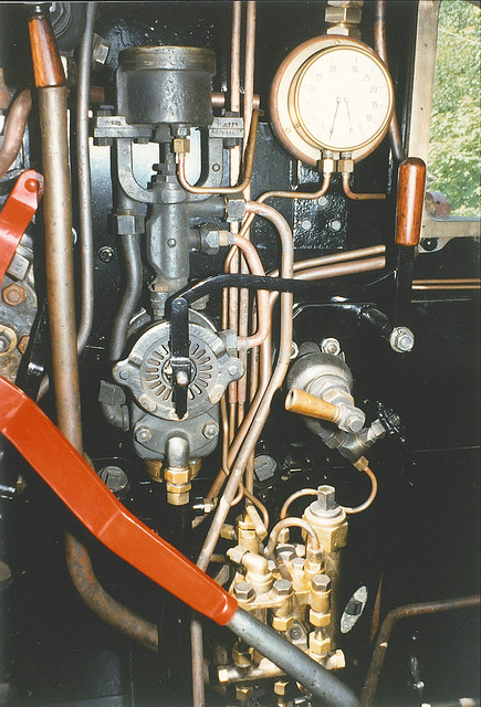 c5 c5 by Roger Froud, on Flickr Wilf |
|
Gary L
Elder Statesman
Posts: 1,208
|
Post by Gary L on May 25, 2021 15:48:25 GMT
Gary can you please advise me as to why David Adams shows the lubricator sight glasses on the left hand side of the back head and yet yours are on the right hand side? The model shown a few years ago at the Midlands Exhibition also had them on the RHS.I understand David used works drawings as the basis of his design but you have obviously done a lot of research for your model. Hence my dilemma. I am still struggling to find photographs of 1501. I intend that my model will be based on 1501 as it was built i.e. with the rear steps facing backwards. I apologise if this has all been discussed before. As you suggested I started to read the Speedy thread but at over 700 pages it would take an age to get through them. Martyn Hi Martyn Wilf’s photo says it all really. Adams’s Paddington backhead doesn’t bear even a passing resemblance to the real thing. It’s a bit if a downer if your boiler has already been completed to the Adams layout, but it can be adapted. It is of course impossible to create a scale backhead for a working model; all controls have to be handled by full-size fingers, not ⅛ scale hands, and a scale water gauge just couldn’t work at all. But there are characteristics of layout and style that you can emulate to get the Swindon ‘look’, which was consistent across nearly all classes and ages. Thus there is the sight-feed on the right, the regulator quadrant, the single water gauge on the left, the fountain on top and the injector steam pipes running down the centre and dividing at the firehole tray. Adams worked from a Swindon GA drawing, and as far as I can see only a GA drawing- if it wasn’t on the GA he guessed, and often guessed wrong. The lubricator pipes that he drew passing through the boiler on the LHS are a good example, they are just wrong both in fact and in principle. Roger’s thread has numerous photos of 1501, so that is your starting point for pictures. Then look up the website of the 1501 preservation society (I forget the URL, but it is linked a couple of times from photos in my thread.) There are lots of helpful people around here too, several are GW experts, so I strongly recommend you start a thread with some photos so people can see how you are progressing and understand the problems. HTH Gary |
|
Gary L
Elder Statesman
Posts: 1,208
|
Post by Gary L on May 27, 2021 0:22:41 GMT
I'm picking up the story now from May 14th. The outer skins have been put on one side for the time being; I've realized that it will be best to finish the inner access panels first. They fit inside the outer skins, so it will be easier to trim them to size, in fact to do everything necessary, before doing any more work on the outers. Also the outer skins will be permanently attached eventually, along with the frame parts, whereas I might need to unscrew certain of those frame parts for easier drilling and tapping for the inner access panels. So with the smaller, flat, rear access panels finished, it is time to turn to the forward panels, which need to be curved to (approximately) fit round the boiler. First job, after squaring off the sides was to roll them to get the curvature. The Formit was almost exactly too narrow to accept them, by about ¾" (duh!) but fortunately the club has a bigger set of rolls which I was able to use. They were rather worn unfortunately, so the rollers were not perfect cylinders, but that's another story. Suffice to say, after a struggle I achieved a reasonable fit to the pannier frames, but didn't take any photos... My Formit was, however, just wide enough to admit the panels lengthways in the bending department as you can see:  However the full set of 'fingers' was not wide enough in total, hence the 'gap-toothed' effect in the picture above. This was not the end of the world; by bending in small bites and sliding the work from side to side each time, any imperfections were smoothed out and are almost unnoticeable:  These bends at each long edge are required to fit to the frame edges. You will note that the plates are well over-width; this folded edge only needs to be ¼" wide, but you need a bit more width for ease of handling. (It was also a precaution against getting flats at the ends of the curve in the roller, but I've since learnt there is a startlingly simple way of minimising this- just reverse the plate in the rolls!) In this photo, the bent edges have been bashed flat to remove most of the curvature in them. In the photo above, the angles are being checked in the frame, and it is pretty close... Now to centre and align one of the frames on the table of the mill, and then use a wiggler and the ÷2 function on the DRO to find the exact centre of the plate. This is the datum I will use to locate and drill for the hideous quantity of 6BA tapped holes:  Now you would expect that it would be helpful to rough-trim back the excess metal on the bent edges first, to more closely fit into the frames? Me too! But it didn't work out that way because this is what happened:  The photo would be clearer if the bench top was not almost the same colour as the brass, but you can see that the trimmed edge has developed a curve, partly releasing the stresses built up in the brass by the rolling and bending. The brass was the normal 'half-hard' to begin with, and the rolling and bending has left it tough and springy- too much to remove this adverse curvature by hand (it is 18 SWG by the way). It will however lie flat and straight when clamped or screwed into the frame, so it isn't fatal, but it makes it more difficult to drill a line of straight holes in it! (Should that be a straight line of holes? Anyway YSWIM.) So I'll leave the other edges uncut till after the drilling; and that will be the subject of the next exciting instalment! |
|
Gary L
Elder Statesman
Posts: 1,208
|
Post by Gary L on May 28, 2021 0:27:37 GMT
'Next Exciting Instalment'Here we are with the plate clamped in position on the frame, which we finished the last instalment setting up carefully in X and Y on the mill table with the DRO Zeroed at the exact centre in each direction. So irrespective of the excess material (or not) beyond the folds, by measuring and setting correct distance from Zero, the drill will always find the exact midline of the frame bars. You can see how clamping it down has removed the bend in the rough-sawn edge:  The 'divide line' function has been used to space 16 6BA tapping holes at 0.8438" centres (that's 27/32") with the datum zero at exactly midway; then back again to drill a clearance hole through the plate, and then a third time with the tapping tool you can see in the photo. The spacing of these holes is a bit of an issue. Firstly (I might have mentioned) the frames themselves are only 5mm thick instead of the ¼" specified in the drawings. This is manageable, but not ideal, and was determined by the material available to MEL at the time. It does call for some precision when tapping holes into the edges, as there is little room to spare. Fortunately the DRO can give this precision (subject always to the immutable law of GIGO: Garbage In- Garbage Out). The longitudinal bars are the full ¼" as drawn, giving slightly more margin for error if you don't have a nice machine like this one. Secondly is the spacing. For the flat Rear Access Plates I stuck to ¾" as drawn, though I think this is a bit closer together than really necessary, even though I am using 18 SWG not 16 SWG as specified. But for these front panels, with a curve across the height and a fold running the full length, the material is given extra rigidity in both directions. Adams shows ¾" spacing again, though in a rather vague fashion, and I couldn't use this anyway, because the holes would conflict with the frame screws and maybe some of the tank fittings- hence the rather strange spacing. (I know you can vary the spacing to get round obstacles, but that complicates the use of the divide line function considerably.) For the holes in the curved edges, life will be much more tricky. You can see I have already inserted one screw each end at the exact centre height of the curve (which is offset towards the top, BTW). The remaining screws have to be drilled radial to the curve, and lacking a large angle table this will be very awkward. However the curvature imparts significant extra stiffness, so I think I will be able to increase the designed hole spacing by quite a lot, perhaps by as much as double the specified ¾". This won't make finding and setting the radial positions any easier, but it will at least reduce the number of times I have to do it! To be continued...
|
|
|
|
Post by Roger on May 28, 2021 21:48:00 GMT
Looks great Gary. I would strongly recommend a trial assembly with the boiler and its cladding to make certain that everything fits as it should. I had to trim the inside top of the tank because it was too close.
|
|
Gary L
Elder Statesman
Posts: 1,208
|
Post by Gary L on May 28, 2021 22:28:55 GMT
Looks great Gary. I would strongly recommend a trial assembly with the boiler and its cladding to make certain that everything fits as it should. I had to trim the inside top of the tank because it was too close. Yes indeedy! I’ve done that already with the assembled frames, and it is a very necessary step. Boilers are not precision assemblies, even when made by a professional. I had to carve off (ISTR) ⅜” from the plates either side of the firebox because the accumulated width of boiler plus cleading was too great. It’s OK now. It is one advantage of building the tanks the Adams way (rib and stringer) with a substantial frame instead of ‘monocoque’ with stressed skin (though both ways are equally valid, and the latter is more prototypical.) Gary |
|
Gary L
Elder Statesman
Posts: 1,208
|
Post by Gary L on Jun 7, 2021 1:10:26 GMT
It's been a while since the last update 'cos (erm) nothing much has been happening in the workshop, with other matters conspiring to take up all my time. Also, progress has been very slow (read tedious) even when I have been able to look in there... Still working on those Pannier Tank Access Plates. The rear pair were bad enough, but at least they were flat. The front ones are curved though, to match the boiler (approximately), and this causes a fresh order of difficulty as I'll explain shortly. But let's bring the story up to date. In the last episode I was drilling and tapping for the 6BA screws on the longitudinals, which was tolerably easy though not at all interesting. Having done that, and with the plates firmly screwed in place, it was an opportunity to trim off the strips of waste left after the bending. An ⅛" slot cutter did the job, set to about 3 thou deeper than the plate edge, and about 5 thou inset from the edge of the frame longitudinal. This is to give a little clearance for removing the plates (it won't be done often, but why make it hard?):  With that done, there was nothing for it but to tackle the screw holes on the curvature. First job was to drill a pair of templates from strips of thin steel, to set the desired hole spacing; I decided on 1" (though 1⅛" would have been better, as you will see.) In the photo below, the template strip has been swivelled out of the way for drilling and tapping once the hole position has been fixed. The template sets the Y axis; then, positioning the drill on the X axis so it is exactly central to each 5mm plate is done by finding the frame centre (with DRO and wiggler) and then measuring outwards in each direction- with a great deal of handle-windey, since this has to be repeated after every every pair of holes! If I had a big tilting table, this would have been a lot simpler, but as it was, I had to use blocks and shims to tilt the job so that the drill would be within a degree or two of radial to the curve. I did this by standing a square on edge exactly at the Y hole position, and sighting against a rod held in the drill chuck. In effect, the job had to be set up afresh after every pair of holes. Trust me, this was not a task I could grow to love, and partly accounts for the very slow progress... 
The baffle holes in the laser-cut plates were unexpectedly helpful, in giving something for the clamps to bite on. Below is a better picture of a typical clamping arrangement: 
As if this wasn't bad enough, there was another unexpected difficulty with the tapping. Tapping the extruded ½" x ¼" brass frame stringers had been slow, but 'no taps were hurt in the course of the operation'. But tapping into the edge of the brass plates was more than twice as hard. The grade of brass used for the plates seemed to make a much tougher chip than the extrusion material, with the result that backing off the tap to break the chips (as I was taught to do back in the Stone Age) was inconsistent and fraught. Sometimes the chip would break easily, sometimes no amount of backing off would release the tap. It is a minor miracle that I only broke one tap (a new HSS one -grrr!) while trying to get it out- one broken tap into the alum bath for only 16 holes completed. This was not fun at all. So that is the reason why after completing 4 holes on each frame, I decided not to put in the 5th and 6th I had planned. This left a gap of about 1½" top and bottom, but the access plates seem to be held firmly enough for sealant to do its job, and I convinced myself that tapping a further 8 holes in this recalcitrant material, exacerbated by the intricate setting-up involved, was simply not worth the candle. It would not be visible in any case. So here is a view of the 'finished' (as far as I am concerned!) access plates on one tank, (though not all the screws are in place): 
Functional if not elegant. The plates can now be unscrewed until the outer skin plates have been finally fixed in place, and that will be in the next episode. (Don't hold your breath!) |
|
|
|
Post by Roger on Jun 7, 2021 6:27:22 GMT
Great jog Gary. I'm not sure why you need access to the insides though. Is there an item in there that needs servicing?
|
|
Gary L
Elder Statesman
Posts: 1,208
|
Post by Gary L on Jun 7, 2021 15:04:14 GMT
Great jog Gary. I'm not sure why you need access to the insides though. Is there an item in there that needs servicing? Hi Roger Good question, and “Because it’s on the drawings” is a very poor answer. I think it is partly about fixing on various details like lifting rings. Plus, Adams’s construction plan envisages bolting on the skins via plain through-drilled holes, so you have to be able to get at the backs. I don’t like the idea much, it seems crude and possibly leak-prone to me, but equally I’m not keen on the alternative of tapping for a huge quantity of 8BA * screws (and even less so after doing all the 6BAs for the access panels!) So even starting with grand intentions, it is only prudent to have nutting as a back-up strategy. Rivetting is another possibility, but that also needs access to the insides (much of which will be out of range of my posh rivet-setting tool  ) I can’t really say I like any of the means of fastening on offer, and the uncertainty is slowing down progress. Added to which, a number of other concerns at the moment are cutting down on my time for thinking about it! I knew all along that the pannier tanks would be my biggest challenge, and nothing has happened to revise that opinion! Gary * If I do go the screw route, or indeed the nut and bolt route,I will follow your example and use metric threads. No point in paying premium prices for fastenings that can’t be seen and can’t be removed! |
|
Gary L
Elder Statesman
Posts: 1,208
|
Post by Gary L on Jun 22, 2021 15:29:56 GMT
I'd like to report lots of progress on the Pannier Tanks. There has been lots of thinking, but that and a multitude of other distractions has reduced visible headway to the 'not worth writing about' level. BUT on a job like that, I'm always ready to grab at 'displacement activity' and today's big news is the Cab Windows have arrived from Polly! So I can spend a little while fitting them into the Spectacle Plate, and then the Cab can be finally rivetted and painted, so this is an important step forward. Here is what they look like, fresh out of the packaging:  No, I haven't got 4 right-hand windows! The left-hand 'column' shows the inside of the windows, the right-hand column the outside. The top row are the front windows, the bottom are the rears (note the different handles). Needless to say, being CNC machined, they are a perfect fit in the apertures awaiting them (which I drew a few thou oversize to allow for painting). For the price of a pair of injectors and a steam valve, I am delighted with them! Well worth the wait. You can see that the hinges are included, but what you can't see is that they are ready-glazed as well (in plastic, not glass). For anyone who doesn't have CNC and the drawing skills to go with it, these windows would present a huge challenge, so Polly's product was a no-brainer for me. A key point here for Paddington builders (applies to Speedy too) is that you cannot fit scale front windows, because the boiler backhead (as drawn) is too big. One modern answer would be to order a boiler to the Polly 2251 design, but with key dimensions (particularly the length) slightly reduced to 1.5" scale instead of the slightly bigger scale that David Aitken chose. That particular boiler is virtually the same prototype (No 10), but has the correctly tapered firebox. However most of us seem to have ordered or inherited the David Adams boiler and have to make the best of it... I chose to have the front windows reduced to suit an aperture 80% of the scale size in the Spectacle Plate, but with the frames (and therefore the handles and hinges) to scale width. Polly were happy to accommodate this. As I understand it, they will make GWR windows to any profile, not just for the classes that they list in their 'Practical Scale' catalogue. I did this on the basis that the eye is very sensitive to correct proportion, but is easily deceived as to scale (just ask the Director of Lord of the Rings !) The other way would be to shrink the profile in the horizontal direction, but keep the vertical dimension to scale. This would produce a tall narrow window, more redolent of the Castles and Kings, and any GWR fan would spot the error a mile off... but you pays yer money and takes yer choice. (Said fan would already have picked on the firebox profile anyway, but why make it worse?  ) Above all, don't trust the Adams drawing. Wait till you have the boiler installed in the frames, and an accurate template for the Spectacle Plate profile. By the time you have allowed for the ¼" corner angles (which you will probably need to cut back in way of the windows anyway, but you still need to get rivets in) and some out-of-scale allowance for boiler movement, plus a certain unpredictability in the crinolines and cleading, it is very unlikely that a mere drawing will tell you what size you need. Also, it is much easier to err on the small side, than end up with window frames that are 'almost exactly' too big! Anyway, I'm extremely pleased with them, and will report progress with fitting and finishing the cab in the next few instalments, before getting back to the tank skinning. |
|
|
|
Post by Roger on Jun 22, 2021 16:54:59 GMT
Hi Gary,
Those look great.
It is actually possible to fit scale windows in the Spectacle plate of a SPEEDY, but it is very tight, for the reasons you state.
|
|
Gary L
Elder Statesman
Posts: 1,208
|
Post by Gary L on Jun 22, 2021 18:56:20 GMT
Hi Gary, Those look great. It is actually possible to fit scale windows in the Spectacle plate of a SPEEDY, but it is very tight, for the reasons you state. Yerrrsss…well it certainly wasn’t possible on my Speedy! But I think your ‘Speedy’ is built to rather tighter dimensions all round though Roger! To get an accurate ‘look’, builders have to take account of the fairly wide margins between the windows and the cab sides on the 15xx, so just squeezing in a scale window isn’t enough; you have to get the proportions right relative to the surrounds as well. There are no rules about it; it is very much “in the eye of the beholder” -but some people definitely have a better eye than others. In my view we can’t always work to accurate scale for lots of reasons (in the cab in particular) but we can still try to capture the character of the prototype. An analogy I’ve used before is coarse-scale Gauge O. The track (and wheels) are significantly out of scale, but if the rail, sleepers and chairs are in proportion to each other, the effect is satisfying and handsome. But if you try to use (for example) fine-scale rail on coarse-scale sleepers the effect is horrid; so an accurate scale component but in the wrong position can spoil the whole effect. That’s how I see it anyway  Gary |
|
Gary L
Elder Statesman
Posts: 1,208
|
Post by Gary L on Jul 1, 2021 0:47:12 GMT
Front WindowsHere is a snippet of a drawing of a Spec Plate Window on the 94xx class; the 15xx cab is almost identical: Points to note are: (1) the ingenious catch mechanism. A plate spring is riveted to the cab side, and the end of it bears on the back of the window frame. The eccentric shape on the handle pushes the spring sideways towards the cab side until the window is free to pull back and open. (2) the hinge plates appear from inside the cab to be small items secured with one large bolt each, in a not very well-engineered arrangement. In reality, what you see is just the visible part of the fixed window frame, which doubles the opening part, but can only be seen near the bolts and the hinge pins. The Polly window does not use an inner frame, in the interests of simplicity and robustness, but provides the hinge pin mountings which create the illusion of the full-size item. Only when the window is opened is the deception revealed, but how often do we do that? You can also see that on the real thing, there is plenty of clearance from the boiler backhead. For reasons given in my last post, this is not possible with the standard Paddington boiler. Even with the window reduced to 80% of the scale profile, it is still very tight to the boiler at the inner lower corners: 
The fitting there, was originally identical to the top pin mounting, but after bolting and soldering the pin plate in position I have had to carve away most of the mounting and some of the window boss at the lower inside corner to allow it to open, (and indeed to allow the Spec Plate to fit around the boiler at all!) I knew this would be necessary, but I didn't want to make the window any smaller. As it happens, it worked, but there is nothing to spare at all. The butchery will be all but invisible when the cab is painted and installed. (It looks worse than it is, in the photo, due to tricks of the light). Here's a close-up of the 'amended' pin mount:  The Spec Plate's boiler aperture is (erm) 'generously dimensioned' but entirely masked from outside by the angle infill. Again, it won't be visible from inside, because it is hidden by pipework. Here's the LH window, also carved:  Not pretty, but it works, and it won't be easily visible. And here is the top pin on the RHS:  No carving necessary here of course, except for the shaping of the pin mount itself, which meant cutting off one 'leg' and shaping the other around the bolt hole. I'm very pleased with these windows. The rear windows are dead to scale and will need no modifications at all, but they go in the 'removable' section of the cab, which can wait till the loco is running and the pressure is off. Because of the carving away of the lower mountings, the lower pin plates and their Hex screw 'pins' all had to be soldered in position so they don't disintegrate. This means that installing the windows after painting can only be done by unscrewing the top hinge pin. It is not in an easy place to access, so there will be a considerable amount of cussing and blinding in the process, but I think it can be done. It will only need to be done once! It might be easier to secure it using the smaller bolt through the Spec Plate, but it will be hard to prevent the hinge plate swivelling out of line, since it wouldn't be soldered. Possibly Loctite will suffice; I'll need to investigate further.
|
|
|
|
Post by doubletop on Jul 1, 2021 8:05:06 GMT
Gary
This is a great thread. I've just ordered the John Smiths full platework kit for 14xx from Polly and thought it about time I found out what I needed to put it all together. It didn't take long to find your write up. There's so many similarities between 14xx and 15xx its just like a set of instructions.
While I wait for delivery, I'm told 4 months, I'm getting the tooling organised 3in1 "Formit" is on order and I'm going to give the Polly Rivet setter a go rather than fork out £140odd for the swish piece of kit you've got.
One challenge I know I'm going to have is making the cab and tanks easily removable. I need to do this as 14xx has internal Stephenson gear and geting them off helps enormously with servicing. I can get my existing cab and tanks off in about 20 mins. The tanks being dry with 10Kg of lead in each to aid with adhesion.
Keep up the good work.
Pete
(I thought I posted this yesterday, apparently not
|
|
Gary L
Elder Statesman
Posts: 1,208
|
Post by Gary L on Jul 1, 2021 8:38:48 GMT
Gary This is a great thread. I've just ordered the John Smiths full platework kit for 14xx from Polly and thought it about time I found out what I needed to put it all together. It didn't take long to find your write up. There's so many similarities between 14xx and 15xx its just like a set of instructions. While I wait for delivery, I'm told 4 months, I'm getting the tooling organised 3in1 "Formit" is on order and I'm going to give the Polly Rivet setter a go rather than fork out £140odd for the swish piece of kit you've got. One challenge I know I'm going to have is making the cab and tanks easily removable. I need to do this as 14xx has internal Stephenson gear and geting them off helps enormously with servicing. I can get my existing cab and tanks off in about 20 mins. The tanks being dry with 10Kg of lead in each to aid with adhesion. Keep up the good work. Pete ( I thought I posted this yesterday, apparently notGlad you like it Pete I think it is always good to make parts easily removable, you never know when something inaccessible is going to break or jam, or seize or fall off (not too often we hope, but still a pain!) I have certainly amended the fastenings on Paddington's cab with this in mind; the pannier tanks are not in the way of anything much. Good access always helps, though TBH access to inside valve gear will only be improved a little, because the boiler is the main obstruction. The attraction of the 15xx to me is that it is the only GWR/WR tank engine that has the valve gear outside, where it is more convenient for fat 12'' to 1ft fingers to work on. The 14xx is a prettier engine though, and worth building for that reason alone. Good luck with the build- let us know how you get on! Gary PS. Perhaps it's the International Date Line?? |
|
|
|
Post by doubletop on Jul 1, 2021 8:51:27 GMT
Glad you like it Pete I think it is always good to make parts easily removable, you never know when something inaccessible is going to break or jam, or seize or fall off (not too often we hope, but still a pain!) I have certainly amended the fastenings on Paddington's cab with this in mind; the pannier tanks are not in the way of anything much. Good access always helps, though TBH access to inside valve gear will only be improved a little, because the boiler is the main obstruction. The attraction of the 15xx to me is that it is the only GWR/WR tank engine that has the valve gear outside, where it is more convenient for fat 12'' to 1ft fingers to work on. The 14xx is a prettier engine though, and worth building for that reason alone. Good luck with the build- let us know how you get on! Gary PS. Perhaps it's the International Date Line?? It was a lesson learned when I started this lark with my father’s nearly completed Rob Roy. He was an instrument maker, not a loco person and he'd built it over a number of years, layering one thing on top of another with not thinking about maintenance. Taking it apart to finish it was a struggle but it was enough to make me think about being able to get to things. The Dart boiler does get in the way a bit, but I can get mine out in another 30 mins. That is if I remember to take out the blowdowns!! I was struggling the other day wondering what was getting in the way, then I remembered. Anyway less about me back to your thread.... Pete |
|
stevep
Elder Statesman
Posts: 1,070
|
Post by stevep on Jul 1, 2021 10:40:42 GMT
When I built my Rob Roy, I wrote the assembly process in a notebook, so I could dismantle it in the future. Some 30 odd years on, that book has been a godsend several times.
I use the rest of the book as a running log.
|
|
Gary L
Elder Statesman
Posts: 1,208
|
Post by Gary L on Jul 1, 2021 11:43:59 GMT
When I built my Rob Roy, I wrote the assembly process in a notebook, so I could dismantle it in the future. Some 30 odd years on, that book has been a godsend several times. I use the rest of the book as a running log. Great minds, obviously Steve! I do exactly the same, except of late this thread has replaced the notebook. But the running log is invaluable. I keep a note of defects and what I've done about it, so that at the next run (which might be several weeks or a whole winter later) I know what to look out for and test. I log the miles run too, which is illuminating; my driving truck has a bicycle speedometer attached. Gary |
|
stevep
Elder Statesman
Posts: 1,070
|
Post by stevep on Jul 1, 2021 12:05:09 GMT
SNIP ... my driving truck has a bicycle speedometer attached. SNIP Gary Mine too. |
|


 )
) ) Above all, don't trust the Adams drawing. Wait till you have the boiler installed in the frames, and an accurate template for the Spectacle Plate profile. By the time you have allowed for the ¼" corner angles (which you will probably need to cut back in way of the windows anyway, but you still need to get rivets in) and some out-of-scale allowance for boiler movement, plus a certain unpredictability in the crinolines and cleading, it is very unlikely that a mere drawing will tell you what size you need. Also, it is much easier to err on the small side, than end up with window frames that are 'almost exactly' too big!


