Gary L
Elder Statesman

Posts: 1,208
|
Post by Gary L on Jul 2, 2021 0:17:52 GMT
Following on from yesterday's post, I've determined that the windows can be easily removed by loosening just the upper hinge pin Hex screws, so the upper pin mounts can also be soldered permanently in position. But first, to add some dummy rivets around the window frames. These are just ordinary R/H rivets, but they don't join anything, and the back of the rivet holes are lightly countersunk. Clip to length, a light squeeze with the rivetting tool and job done. File off the backs flush, and they are almost invisible. I'm not a massive fan of dummy anything, but there are lots of places where it is unavoidable, and this is one of them. So this is what the finished Spectacle Plate looks like, prior to rivetting it into final position in the cab:  The circular plate on the LHS represents a patch that all the 15xx carried, due to re-routing of the ejector exhaust pipe to a position nearer the roof. I don't know when this was done, but as usual you need to decide what date you are modelling if possible. Here is a view of the Spectacle plate loosely assembled in position:  (I haven't added the retaining spring plate yet) I won't show the RH side, because a pipe fouls the hinge boss on that side, so I need to reroute it. I've just remembered that the angle trim that covers the cab-firebox joint needs some short extensions each side to cover the pannier tank-cab joint. So I think I will have to temporarily bolt the Spec Plate in position, until the tanks are finished enough to mark the position of the trim angle for soldering in position. Maybe I'll put some small rivets into the angle trim as well... but when do you stop? Here is a reminder of what this area looks like on 1501; I believe this is one of Roger's excellent photos:  You can see how the real-life firebox profile is significantly lower and narrower, hence the need for smaller windows in a model that uses the Adams boiler. The difference is plain to see, comparing the two photos, but without the prototype photo in your hand, I think the proportions of the windows are reasonably convincing. For me, there's no alternative anyway, so I won't obsess about it! Finally, here is the view from inside the cab of a (very tall) scale fireman:  Note how the ¼" brass angle needs to be scalloped to clear the window frame. Also the window handles will need a bit of shaping; as supplied they are just flat brass. That won't be problem. |
|
|
|
Post by theflyingscotsman on Jul 3, 2021 22:21:47 GMT
wow, that looks brilliant. i've enjoyed looking through some of the methods you used and will where possible be applying them to my loco
|
|
Gary L
Elder Statesman
Posts: 1,208
|
Post by Gary L on Jul 4, 2021 0:47:57 GMT
Thanks theflyingscotsman. I'm learning, like all of us, and there is quite a lot of luck involved when it goes well! Back to the Pannier Tanks now. After the bending, and a little bit of fine adjustment at home, I clamped the skins in place on the frames, and scribed the frame positions on to the inside face of the skins. The lower skin panels were then taken to the bandsaw at the club and cut to the scribed line as closely as I dared. (The upper skins are to be treated differently, because they have to be cut to match the boiler contours. For them, the scribed line will serve as a datum for measuring and transferring the boiler contour to make a cutting line- spiling, as boatbuilders call it.) But that is for later. The LH lower panel was then clamped to the frame again; carefully adjusting for length; in particular to make sure there is just enough overlap at the front end to cover the edges of the cosmetic fascia plate. Then the assembly was transferred to the mill to drill for 8BA x ¼" CSK screws. David Adams's method is for dozens of little screws like these at ¾" spacing to stitch the edges and mid frames to the skins, but I'm rebelling against this, and putting in just enough to hold the skin flush for soldering. The solder will then keep everything watertight and together. That's the plan anyway. The tanks are big and heavy items to heat up for soldering without distortion, so if anybody thinks this is a risky plan, please shout! (I was originally going to use cheap metric screws here, but I find I have plenty of BAs in stock so I will use them first) The tanks are also rather large items to mount on the mill table for drilling. Not for the first time, I'm glad of the baffle apertures for something for the clamps to bite on, at least at the rear end (hidden, at right of the picture):  Adams suggests shallow countersinking to leave the screw heads proud, so that after final assembly they can be filed back flush, removing the screw slots in the process. That sounds like a good idea. As you can see in photo, I'm starting with the middle pair of frames, and for photographic purposes I've emphasised the initial four holes I'm drilling and tapping, with felt-tip pen. You might wonder if there is a need for such accuracy here, but indeed there is. I am drilling blind into the edges of 5mm plate, so the holes have to be precisely positioned lengthwise or I might miss the frames altogether! The easiest way to do this is to set the tank accurately square on the table, then to use the wiggler and the DRO 'halving' function to find the centreline of each frame as I come to it. With screws in these initial holes, I can work outwards to put a few more into the longitudinal centre rib, and the outermost frames. |
|
don9f
Statesman
 Les Warnett 9F, Martin Evans “Jinty”, a part built “Austin 7” and now a part built Springbok B1.
Posts: 960 
|
Post by don9f on Jul 4, 2021 19:01:18 GMT
Hi Gary, I have also filed screw heads away, including the slot and yes it works well, apart from the possibility of unintentionally filing away or marking the material round the holes!
I have just finished the process of filling dozens of fully countersunk screws used in the assembly of my current Fowler tender project, with Isopon P38 (from Halfords) and just wanted to remark on how well I found it will adhere to properly cleaned & degreased brass....as an alternative method.
I know your tanks are only 18g, so maybe a bit thin to take the full head depth using that method?
Cheers Don
|
|
Gary L
Elder Statesman
Posts: 1,208
|
Post by Gary L on Jul 4, 2021 23:21:14 GMT
Hi Gary, I have also filed screw heads away, including the slot and yes it works well, apart from the possibility of unintentionally filing away or marking the material round the holes! I have just finished the process of filling dozens of fully countersunk screws used in the assembly of my current Fowler tender project, with Isopon P38 (from Halfords) and just wanted to remark on how well I found it will adhere to properly cleaned & degreased brass....as an alternative method. I know your tanks are only 18g, so maybe a bit thin to take the full head depth using that method? Cheers Don Hi Don Yes, I think you are right on all counts. I prefer to get the metal right, to minimise filling, if only because filling has to be done again for every repaint… though I don’t think that will be my problem… I’m thinking ahead to the soldering stage, and wondering if I will get a lot of trouble from distortion, bearing in mind that my fastenings are about 2” centres, not ¾” as Adams shows. I’d like to ‘do the job properly’ but there is the alternative of using adhesives. Sikaflex (for example) makes an excellent bond; the down side is that it will bleed out of seams and make them difficult to fill and paint over. Gary |
|
Gary L
Elder Statesman
Posts: 1,208
|
Post by Gary L on Jul 13, 2021 0:04:32 GMT
Work on the tanks proceeds at slightly more than glacial pace, but it is possible to see an end in sight. The current task is fixing the outer skins in place on the frames, and that has been completed for the lower half of each tank, as you can see here:  In the picture, the lower tank is right-way-up, the upper one is upside-down. There is nothing very unusual or even very interesting to comment on here, except for one thing. I trimmed the lower skins to fit the framework exactly, as not hinted at even vaguely in Adams dwg no 21. He shows a profile which might be the top of the tank, to be shaped on the job to make a close fit to the boiler cleading. This is very necessary for the top surface, even though an infill plate is used on the prototype- the infill plate will need this extra support on my model. (I think Adams is suggesting that careful profiling of the tank top makes an infill unnecessary, but I'm not going that route) For the lower surface though, I cut the plate edge flush to the frame, so as to locate the holes for the 8BA screws from the edge of the tank frame itself, without having a rough-cut plate edge in the way. After offering the plated tank to the chassis, I realised that this results in a significant gap alongside the firebox, because the full-size tank follows the waisted profile of the firebox sides, whereas the model tank presents a vertical flat surface. I doubt if anybody will notice this on my model, but anybody following these notes might choose to make a better job of it. Another feature of this job, is that when you turn the tank frame to sit upright on the mill table for drilling and tapping the underside, there is little room to spare under the quill, even at its highest extension. This is not a problem for the drilling, but the tapping is more of an issue:  I have a variety of tap holding devices, but this is the only one that would fit in the available headroom, and there is barely a quarter-inch to spare. It has an M2 taper fitted into a M3 adapter sleeve. The securing clamps act on the frame stringer furthest from the drill, which is not as rigid as is desirable. A machine jack or two, propped up on a suitable spacer(s) as shown, improves this significantly when drilling. I mentioned a few episodes back, that the edges of the laser-cut frame brass are much tougher to tap than the extruded brass stringers (which are easier still by virtue of being through-drilled, rather than blind). For the record, I'm a bit slow sometimes, but the fix is obvious- drill the tapping hole a size bigger, in this case 1.9mm instead of the 1.8mm in the thread tables. Great care is still needed, but no more taps have been injured in the course of this production... Before moving on to skin the upper half of the tanks, there are a couple of jobs that will be easier done now, including marking and drilling the tank support pads and the flanges for the balance pipe, so that will be covered in the next instalment. |
|
|
|
Post by doubletop on Jul 23, 2021 22:55:30 GMT
Gary, if you want to make one similar to the one you show on ebay then Polly sell a casting and drawing for £24, it is advertised as 75mm (I guess the throat depth). They also have snaps at £21.50 per set Chris D PS, the metal bashing is excellent, just goes what you can do with a bit of planning and perseverance, well done. An old post but as I'm tooling up to do my Dart platework I went to Polly to order their riveter kit. They don't stock it now and it has been removed from their recent catalogue. However, I did ask if they still had the drawings and they kindly sent me a copy. Very easy to fabricate, no need for castings and you can make the throat as deep as you need.  In the interests of supporting the suppliers the originator can be found here www.ateliermb.com/shops/gussteile/eu/contents/en-uk/d32.htmlHopefully useful to somebody doing a similar job to Gary. Pete |
|
|
|
Post by steamer5 on Jul 24, 2021 1:20:23 GMT
Hi Pete,
The water cut guys are your friend! Had them do a couple of the number 12 bits...NOT this design.....i got a 16 ton hydraulic crimpler on mine....a bit of an overkill but the price was right!
Hope things a well down your end of the country
Cheers Kerrin
|
|
|
|
Post by doubletop on Jul 24, 2021 2:51:27 GMT
Hi Pete, The water cut guys are your friend! Had them do a couple of the number 12 bits...NOT this design.....i got a 16 ton hydraulic crimpler on mine....a bit of an overkill but the price was right! Hope things a well down your end of the country Cheers Kerrin Kerrin Hi I'm thinking of using aluminium tool plate and tubular handles to keep the weight down. It's not like 16 tons is required for the rivets for this job and lightweight may reduce handling errors dinging the platework. What is more, I've got the material to hand. Things are well down here thanks. Surviving the winter reasonably well. Pete |
|
Gary L
Elder Statesman
Posts: 1,208
|
Post by Gary L on Jul 25, 2021 0:09:25 GMT
Hi Pete, The water cut guys are your friend! Had them do a couple of the number 12 bits...NOT this design.....i got a 16 ton hydraulic crimpler on mine....a bit of an overkill but the price was right! Hope things a well down your end of the country Cheers Kerrin Kerrin Hi I'm thinking of using aluminium tool plate and tubular handles to keep the weight down. It's not like 16 tons is required for the rivets for this job and lightweight may reduce handling errors dinging the platework. What is more, I've got the material to hand. Things are well down here thanks. Surviving the winter reasonably well. Pete Hi Pete, Kerrin et al The biggest rivets I will use with my deluxe stainless aircraft riveter are 1/16", and I agree; the rivetting force is not great, and the tool could cope with significantly bigger fasteners. Both your proposals are sound, but I would advocate for as deep a 'U' as possible so that you can access as much as possible of a joint running across a plate from top and bottom when the end of the plate is closed (IYSWIM). Of course, the deeper the U, the stiffer it needs to be, which is why the price of the tool increases exponentially as it gets bigger. (I'm not in my workshop at the moment, but mine is about 3 or 4 inches). For this reason, I would suggest a casting with substantial ribs is more likely to be satisfactory than an item cut from plate, unless you can add some ribs by welding or brazing (with attendant risks of distortion) -or even by rivetting! Mine is quite heavy, but I generally (possibly always) use it with the U body clamped in the vice. Platework is quite delicate, even in 7.25" gauge, and you need to be able to feel the pressure of the riveter and stop squeezing if it tries to force the plate out of true. Used freehand it is very cumbersome on my work, though probably not so bad on aircraft structures. You might wonder why not make a tool with a column and a base (as you sometimes see), but it is the ability to change the orientation in the vice that makes it much more versatile. Another bonus, completely unexpected, is that I can swap the anvils around, top for bottom and v-versa. This can be very useful for dummy rivets, with snap head at one end and a flush countersink at the other. Sometimes changing the snap anvil from the static to the moving head makes all the difference between being able to reach the rivet or not. To any doubters I would say that the alternative of using a traditional hammer and sets is just so much more awkward, more slow, more inconsistent that I regret not buying this tool a lot earlier- even though there were relatively few rivets to set until I came to the cab and bunker. And tap-tap-tapping the rivet causes the head to harden, which is not helpful. A controlled squeeze gives a far better job. Last observation, which applies to all riveting. It is vital to plan the sequence of riveting, or you end up like the riveting equivalent of painting yourself into a corner so you can't get out of the door. It still happens sometimes, and the favourite 'get out of jail' tool is a small sharp cold chisel, but not ground to the usual isosceles edge. Mine has an edge like a wood chisel, so you can lay it flat on the plate, edge to the offending rivet head. A light tap will behead the rivet cleanly and leave no marks at all. HTH Gary EDIT. Thanks for the link Pete. That has gone into my bookmarks. Not a big range but an unusual one, and the riveter castings will be very useful to those who like making their own tools (which I don't!). It's a pity that Brexit adds to the cost/difficulty of UK buying direct from Europe. |
|
Gary L
Elder Statesman
Posts: 1,208
|
Post by Gary L on Jul 26, 2021 0:45:22 GMT
With the Lower Tank Skins screwed into position, and then trimmed back to the frame, there is now some important and rather critical marking and drilling to be done before anything else happens. First there is marking out the Upper Tank Skin. This has already been scribed with the top outline of the tank frame (see July 4th posting), to establish a marking datum. Now the tanks can be clamped onto the loco, complete with the lower skin (but not the upper). This needs to be done very accurately, as we are going to mark out for the Tank Pad fixing bolts and the Balance Pipe at the same time:  The strings in the picture are safety lines- I don't want the tanks falling to the floor before they are properly clamped in place! The tank heights and levels need to be adjusted with shims under the tank pads. Full-size uses ¼" wood packing, presumably as an anti-drumming measure; I shall use some butyl pond liner which is a good colour and about the right thickness. Rubber is virtually incompressible, so I can add a layer or two if levelling is necessary. I have one of those little electronic protractor boxes, which can be zeroed to act as a spirit level to 0.1 degree, so zero to the top of the frames, and then level the tank frame to it- easy peasy. Aligning the tanks laterally is a bit more tricky. They must be flush to the cab at the back, and then parallel (of course) to the frames. On the "measure thrice and cut once" principle, time spent on this is unlikely to be wasted. Then clamp everything securely for the next steps. As noted, the position of the top of the tank frame is scribed on the inside of the upper skin. So measure at a number of stations from the frame to the boiler cleading, making sure the rule is perfectly level:  ... then transfer the measurement to the skin, from the scribed datum line. Join up the dots with a second scribed line, and this is the line for bandsawing the top edge profile to:  If you follow the Adams drawing, where the tank edge is exposed, then you should insert some 18g packing under the rule, so you can bandsaw tidily to the upper edge of the plate and then bevel the underside to suit. But I shall follow the prototype practice of adding a thin trimming plate to mask the gap, so the actual tank edge can be fairly approximate and bevelling will be unnecessary, as long as there is a small gap to keep it clear of the boiler paintwork. Then the Tank Upper Plates can be put on one side for a while, while we turn to some important additions to the lower plates... |
|
stevep
Elder Statesman
Posts: 1,070
|
Post by stevep on Jul 26, 2021 8:26:19 GMT
Brave man, doing all that measuring against the pristine painted boiler cleading!
|
|
Gary L
Elder Statesman
Posts: 1,208
|
Post by Gary L on Jul 26, 2021 16:45:37 GMT
While the tanks were clamped in place, I scribed around the tank mounting pads and through the bolt holes. This gives a check against gross errors, but I never get particularly accurate results this way, especially since, here, there is a degree of slop in the mountings- intentional, but it means that the pads could have been slightly out of position from the start. I like to confirm the scribed positions where possible by measurement from fixed parts of the structure. To do this, the first step is to screw the tanks firmly to a flat surface, upside down. My workshop table (ex-IKEA laminated timber) is suitably rigid, but benefited from running a plane over it to remove the high spots. Not perfect, but this doesn't call for surface plate accuracy. All dimensions will be gauged from the tank bottom, which is currently the top*, so if the tanks are not perfectly square in the vertical it won't matter much:  One tank was easy to screw down (through the filler and vent holes in the frame) but getting the second one accurately positioned was too difficult without some tooling. So first I made a gauge to set the width between the tank outer skins- this dimension (12.75") has to be identical to the width of the cab. A length of steel bar and a couple of scrap lugs was all that was needed. I also needed a square, but my biggest was nowhere near big enough for the overall width. Solution was to clamp a rule to extend the blade of the biggest square (not shown; or -since this is a Swindon loco- perhaps I should say not shewn):   Once again, this is best not rushed, and checked at every stage. First items to locate are the rear tank mounting pads. The single upstanding studs made good fixed points to measure the exact distance from the cab front, and then across the frames beneath the boiler. Provided those are correctly placed and the pads are squared, nothing can go wrong (it says here!). There are two countersunk 4BA screw holes in each which will secure the pads through the skins and into the frames. When everything was as it should be, and clamped up tight, I spotted through those holes with a Black & Decker, to be drilled and tapped properly later. You can see the 'deliberate mistake' here. At the firebox I had to make the tanks narrower than the drawings, to compensate for excess width in the firebox cleading. The Rear Tank Pads are made to prototype dimensions, so they overhang the inside edge of the tank rather a lot. I don't think this will matter structurally, and it will be out of sight, but if I'd thought about it before trimming the tank skin, I'd have left a lug of skin plating to mount the full width of the pad on. But I've said already that I would have left the skin wider in way of the firebox anyway, to match the prototype dimensions. Too late, what's done is done! You'll need an inspection mirror to see it in the finished product:  A similar method was used for the front pads- you can see them in black at the top of the photo. However these were too awkward to clamp, so I had to rely on square and centre-pop to mark the hole locations. All these items were previously drilled using DRO coordinates on the mill, so any errors will be limited to the marking out on the skin, and I will use coordinate drilling to at least make sure the pattern is accurate. The last item that must be marked out before this rig is broken up is the Balance Pipe. The method will be much the same, but I haven't done it yet... *Famously the RN once applied this label to shell casings, during the changeover from muzzle-loading to breech loaders I believe. Thus "The bottom is labelled TOP to avoid confusion"  I'm sure it made perfect sense at the time. I'm sure it made perfect sense at the time. |
|
Gary L
Elder Statesman
Posts: 1,208
|
Post by Gary L on Jul 26, 2021 23:24:19 GMT
And here is the Balance Pipe:  Clamped into position, and spotted through the flange holes. There are two additional flanges to support the joint, these will be screwed and soldered to the tank skin once the rectangular waterway holes are cut out.
I forgot to mention there is an issue with the Tank Front Support Pads. The foremost bolt holes where they are fastened to the skin, are about ¼" in from the tank front. My tank fronts are 5mm thick plus a 16g fascia plate which adds up to -um- about ¼", so the centres of the bolt holes will fall almost exactly on the inner edge of the plates.  This can be resolved by adding a doubler strip of ¼" sq brass in way of the bolt holes, so the drill and tap can stay within solid metal. It would have been easier if I'd done it before assembling the tank frame, but we are where we are. Something else where those coming after needn't make the same mistake! It isn't evident from the Adams drawings either, but at least it won't be very difficult to fix. |
|
Gary L
Elder Statesman
Posts: 1,208
|
Post by Gary L on Jul 31, 2021 0:29:03 GMT
After the marking-out and spotting, the tanks were unscrewed from the table-top and returned to the mill for drilling and tapping. Like the marking and spotting, it is important now to drill to the marks as precisely as possible, so that the tank mounting pads will screw accurately onto the tanks, and then the mounting studs on the pads will meet the supporting brackets attached to the loco frames. Mistakes here could be cumulative, and we want the tanks to fit snugly to the front of the cab (without being attached) and the tank sides to be flush with the cab sides. It's the difference between looking like an engineering product and looking like a shanty town... However once the alignment is done, there is nothing very interesting or special about the actual drilling, so I won't go into details. There is a pointed wiggler tool in the set, which is useful for aligning the drill to a pop mark (though the pop mark needs to be accurate to the scribed cross-hairs, which is easier said than done I find!) If using a normal HSS drill (as opposed to carbide) I find I can set the drill quite well to a spotted-through drilled mark by watching the rotating drill tip just kissing the mark. You can see (and hear) the drill tip deflect if it is not perfectly central, even if it is only a few thou out. Of course this only works when the drills are thin enough to be flexible, but it does it for me... There is also a big hole (¾" dia) to bore for the vertical conduit that passes the feed pipes from the injectors below, to the top feeds above the tanks. Adams draws the feed pipes passing between the boiler and the tanks with a notch cut out of the inner tank edge. This is very logical from the engineering POV, but as Roger has commented, it is slightly baffling that Swindon chose to do it by adding a large-bore duct passing through the tanks themselves. But they are a very prominent feature, seen from above, as most 7¼" gauge models are. Here is the duct hole opened out with a step drill...  ...and here it is being finished off to size with a boring tool to suit the copper pipe that is waiting to form the ducts themselves:  For anybody who wants to copy this feature, the duct pipes scale at 5½" i.d., 3/16" wall thickness, and the centres are 6' 10½" from the tank rear/cab front, and 15¼" from the outer vertical face of each tank. Roger struggled to fit them in his Speedy tanks and had to resort to judicious bending, and I shall have to do the same, though there is another option, of contouring the inner access panel, if there is enough clearance (I think there is). These pipes are large enough to hide the necessary union to split the feed tube, otherwise the bends at top and bottom would make it impossible for the feed tubes to enter the pipes. And since the unions have to be there anyway, it is only slightly more effort to add a clack ball, to supplement the 'official' clacks either side of the safety valve. This shouldn't be necessary, but I've done it anyway! With all this done, the lower half of the tanks are complete, so I attached the mounting pads and offered the tanks to the loco to check that the tanks would fit in place. I'm pleased to say they did, though I inconsiderately forgot to take photos, sorry! With some dummy packings in place, I was able to accurately mark out the contour of the tank tops on the Spectacle Plate. From this I will be able to add the covering angle, and then finish the assembly of the cab at last. |
|
Gary L
Elder Statesman
Posts: 1,208
|
Post by Gary L on Jul 31, 2021 23:36:43 GMT
One of the 'tidying up' jobs I want to do before embarking on the Tank Upper Skins, is (are) the cosmetic false fronts for the pannier tanks (I'm going to call them Fascias for short). These are needed for various reasons- there is a big gap to fill between tanks and boiler at the front, and a surface is needed to mount the handrails and steps. Above all, it hides the structure of the tank frame, which is non-prototypical and shouldn't be there by rights- the full-size tanks are all-welded 'stressed skin' construction, which is not very easy (for me!) to replicate accurately in a model. Anyway, the point is, I had the fascias laser-cut oversize, to the outside profile of the skinned tanks, in case anything went wrong with the bending of the skins. I had cut the skins to exact length pre-bending; which squared everything up nicely for the bender. But I knew that if the bending went a little off-square for any reason, the skins would have to be trimmed straight at the ends, and that would leave them short, and it would then be expensive to shorten the frames (new stringers needed). If that happened, I could circumvent the drama by trimming the skins back to the frame, and taking the fascia plates out to the very edge of the tanks. Fortunately nothing bad happened, so the fascias can sit inside the plates of the tank skins, as intended. But that meant that I needed to remove approx 1/16" from 3 sides, which I scribed 'from the job' as LBSC used to say. Removing the excess metal by hand would mean rather heavyweight filing, but the mill makes life much easier, taking care not to cut too far:  The rounded corners, and the last few thou were trimmed to the frame profile with a file. This would have been very awkward if I had forgotten, and left it till after the tanks were soldered up! Anyway it is done, so the fascias can be put on one side till I'm ready to add the cosmetic details. |
|
Gary L
Elder Statesman
Posts: 1,208
|
Post by Gary L on Aug 2, 2021 23:43:09 GMT
Next 'tidying' job is finishing off the Spectacle Plate, by completing the angle that covers the gap where the tanks join the cab front. You can just see it in this picture from the Engine House in 2009, before 1501 was refurbished. The angle that covers the firebox joint is already done, it is just the short section that covers the top of the tanks and extends down the radius that is needed, and now that I have been able to scribe the tank profile on the Spec Plate I might as well get it done:  Exact scale is impossible because of the overscale backhead, so the best I can hope for hope for is to give a decent representation of this part of the loco. First thing to do is to make a fresh former for my crude angle bender, then insert the annealed thin brass angle and -erm- bend it:  There are no easy ways of getting a nice bend in angle, and this tool isn't great, but it did the job. If you try to curve too tightly, or too far (beyond about 90 degrees), this device will split the angle open at the apex (as I found!) but luckily the damage occurred just clear of the length I needed. With the curves done, the mitre can be cut, and the angle soft-soldered onto the Spec Plate. Solder paint is ideal for this, applying heat with a small torch from behind, making sure the clamp gets warm enough as well:  Finally, the outer edge can be trimmed off, remembering to allow for the thickness of the cab sides that go outside the Spec Plate. Unlike the section that covers the firebox, there should be no movement here 'twixt cab and tank, so the angle can fit more snugly to the tanks than to the firebox. Add a couple of rivets (somewhat cosmetic, but they also forestall any mishaps) and job done. Well almost- the angle is almost exactly in the wrong place for one of the rivet holes at the cab corner. Examination of the prototype photo shows that Swindon missed out a rivet in this position, probably for the same reason, so the hole will need to be filled with some solder (hurrah for 'cosmetic' rivets, to stop the angle coming adrift!)  Tomorrow the Spec Plate can be riveted finally into place, to finish the cab assembly ready for painting. |
|
Gary L
Elder Statesman
Posts: 1,208
|
Post by Gary L on Aug 6, 2021 0:45:00 GMT
So now the Cab is all rivetted up and finished, except for painting*, and of course adding the handrails and other details which are all complete, but the painting must be done before they can be reattached: 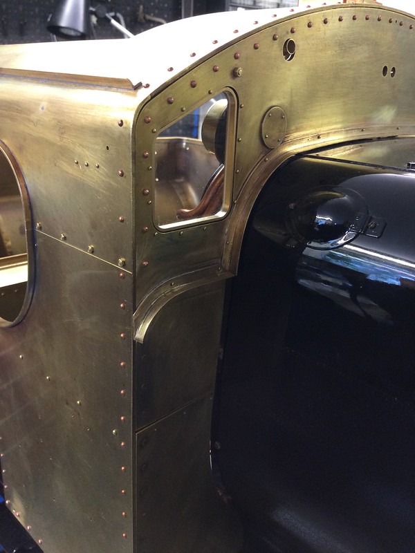 Here is a trivial item, but an oddly satisfying one, the 'catch' arrangement for the Spectacle Plate windows. As on the full-size, they are kept closed by a leaf spring (phos-bronze strip in my model, retrieved from a redundant electrical device). You can see it, secured by tiny rivets, to the right of the window frame in this picture. (They are bolts in FS, but that would be impossibly fiddly here):  As far as I can tell, in the FS version, the blunt end of the leaf spring bears on the back of the window frame, holding it shut, and the handle hangs vertical and clear of it. To open the window, the handle is lifted; the semicircular 'cam' makes contact with the leaf spring, pushing it sideways until it clears the window frame, whereupon the window can be pulled backwards and open with the handle:  If If that is indeed how it works in FS, I couldn't make it work to my satisfaction in the model. The clearances and precision required in the spring deflection did not give a good result. So instead of the spring bearing directly on the rear of the window frame, I formed the tip into a 45 degree angle, so it bears on the rear edge of the window frame in the manner of a clip. It is hard to describe, and even harder to photograph, but this gives a smoother action, and restrains the spring from coming too far inboard. If not restrained in this way, the spring bears on the handle cam and deflects the handle at an unnatural and unprotypical angle. It has the side benefit of making the window slightly more damage-proof too- a determined thump will overcome the spring and the window will spring open, instead of being broken. Not that I'll be opening the Spectacle Windows to clear the raindrops very often, but it is nice when these things work as they should! * and the removable section. I will tackle that at my leisure when the loco is up and running. |
|
Gary L
Elder Statesman
Posts: 1,208
|
Post by Gary L on Nov 24, 2021 1:32:23 GMT
It's been a long time since I last did some work on Paddington, but now that the debris from a long spell afloat has been variously tidied away, repaired, or improved, I have rediscovered enough floor space in the workshop to restart the work on Paddington. So first a resumé; as much for my benefit as yours! We left the story after a brief digression in the cab, half-way through constructing the pannier tanks. The framing is complete, along with the detachable covers on the tank faces nearest the boiler. The outer skins meet at the horizontal mid-seam, and the two lower panels are finished, so the next job is the two upper panels. These differ from the lowers, in that the profile of top face needs to be shaped to conform to the boiler. The gap will be closed finally, as in the prototype, by long thin cosmetic infill plates, but they need to be supported underneath for most of their width by the upper face of the tank skin, protruding beyond the framing. NOTE: the Adams plans imply that the tanks themselves will be closely fitted to the boiler (with no infill plates), but I am going to do the job properly, per prototype. If you prefer the simpler D.Adams arrangement, the method below will still be valid, but you will need to be extra careful about profiling the inner edge (and with more detail, at the boiler bands for example); in step 7 you will need to stand the ruler on a scrap piece of plating, so that you mark out the top edge of the plate, not the lower edge, and you probably will need to bevel the edges. Thus, although the Adams method seems simpler, it actually requires very careful work on this profiled edge to get an acceptable visual result, and to any GWR enthusiast it will still be altogether wrong! But I digress. Shaping the top face of the upper skins required some careful marking out, which naturally I forgot to photograph, but the procedure was as follows: - Unscrew and remove the finished lower skin panels (to prevent interference at any overlap at the mid-height seam, which you need to mark on the plate for trimming).
- Clamp the embryo upper skin panels in position on the tank framing.
- While there, transfer the position of the mid-height seam to the outside of the upper skin panel, to be trimmed back later.
- Scribe the position of the inner edge of the framing longitudinals onto the inner face of the embryo upper panels.
- Remove the embryo upper panels and replace the lower panels (with all their multiplicity of screws!). This is tedious but necessary to find/confirm the exact finished profile of the tanks.
- Clamp the half-clothed tanks into position on the loco, using all the various brackets, pads and packings. Very important that the outer face is exactly parallel to the chassis frames, and square and flush to the cab sides. (Woodworking clamps with soft plastic faces are best for this.)
- Using a rule on edge, applied to the top edge of each bulkhead frame, measure the distance between the tank frame inner edge (corresponding to the scribed line in 4. above) and where the rule corner touches the boiler cleading. Deduct a safety margin (⅛" IIRC) then transfer the measurement to the inside of the embryo plate from the previously scribed line.
This second scribed line is to be sawn along, so previously blackening the plate with marker pen ('Sharpie'?) makes the cutting out much easier for the aged eyesight. Note. This gives a clearance at the lower edge of the top face of each panel. This is necessary, because the plating meets the boiler at a very acute angle, especially near the front. I have no desire (or need) to bevel the edges, because they will be hidden by the infill trim plates. Thus it is the clearance at the lower edge that is important, not the top. It will be hidden anyway, so a high degree of accuracy is not required. After all that, I took the two plates to the club bandsaw, and was able to achieve a fairly close cut. (Without the bandsaw, I would have had to resort to the old faithful jigsaw, and extra precautions against scoring from swarf dust). Again, no photos of the sawing, but here is the result, with the tanks photographed upside down, and the lower skins roughly back in position: First the rear (firebox) end of the RH tank:  And second, the front end: 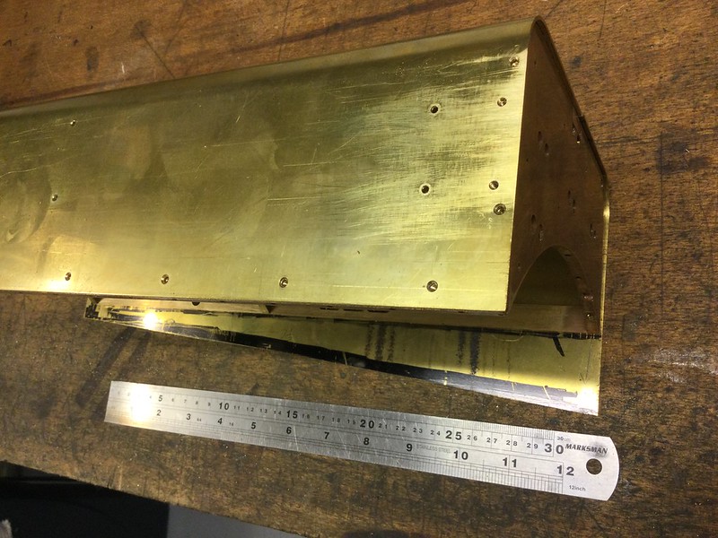 (Note the small overhang at the front of the tank. This is to take a cosmetic fascia plate that will be inserted later.) You can't really see how close the saw cut is to the scribed line, but it is quite close (one of the merits of a decent bandsaw). The pictures illustrate the shaping needed for this edge of the upper plate, where it protrudes beyond the framing. I will run a coarse file along the edges to smooth them and remove the burrs before proceeding. |
|
Gary L
Elder Statesman
Posts: 1,208
|
Post by Gary L on Nov 27, 2021 0:29:40 GMT
So, the preparation done, now to mount the skin for drilling and tapping. (This one is the RHS) The protrusion of the upper skin beyond the tank framework is the first complication, because I can't just clamp the framing down onto the mill bed as with the lower skins. Four identical-height blocks to prop it up on is two more than most people are likely to possess. However the stringers are not symmetrically placed, top and bottom, they differ by about ¾" or thereabouts (I forget). I have a pair of Vee-blocks and a pair of 4-3-1 blocks, and luckily they differ in height by exactly a mm less than the difference I need to make up; so a pair of 1mm shims and that is the supports taken care of. Then it is a matter of lining up the structure so the middle stringer is accurately aligned to the mill bed: (View from behind:)  The wiggler gets me to within about 2-3 thou of parallel which is more than good enough; in any case, the flex in the tank structure makes it very hard to clamp it down and maintain this degree of parallelism. The skin is (of course) just clamped in position; the woodworking clamps in the middle make sure that the central part of the plate is snug and tight to the frames. The rearmost portion of the tank (to LHS of the picture above) can't be drilled on this setting, because the travel of the mill table is not sufficient, but a pair of machine jacks (not shown) will support the extreme end of the structure. (Side view:)  It's quite awkward clamping this up back-to-front, it just happens to fit better on the table this way, because the clamping studs fitted into the Tee-nuts restrict the movement available on the table. And you still have to be able to traverse the work so as to reach all the holes that need drilling. Who doesn't want a bigger mill than they have already got? In my case, I would have to cut a hole in the roof, so it isn't going to happen any time soon... The setting-up took a couple of hours, believe it or not, so the actual drilling had to wait till today; at least to get started:  All of which begs the obvious question- why bother with all this careful accuracy, when (by definition) all these carefully-drilled holes will be completely invisible (I hope!!) on the finished, painted tank? Answer came there none, though to be fair, the holes into the edges of the bulkhead plates have to be pretty accurately centred, because there isn't much thickness to play with. So I will get on with a lot more drilling and tapping. It's mindlessly boring, so I won't report again for a few days, until it is all finished. However I have two tapping tips which might help newbies: 1. The solution to the problems I was having with previous work on these tank skins, in that the brass liked to grab the tap just for fun and make it very difficult to back off, was so obvious that it took me all this time to rumble it. Use a bigger drill! The recommended tapping drill for 8BA is 1.8mm, but I found going up to 1.9mm made life so much easier. (Why didn't I think of that before?) 2. I have several tapping tools for mounting in a drill chuck, but all of them require a lot of headroom that is not available on this job. So, as in the photo, I mount the tap in a suitable pin vice, put it into the chuck, hand-tighten the jaws, then back off just enough to let the pin vice spin. Sorted! Combined with the larger-than-recommended tapping drill, an 8BA tap can be turned happily with just the fingers. I doubt if I could use this method with taps very much larger than 8BA, but it solves the problem here. |
|


 I'm sure it made perfect sense at the time.