|
|
Post by simplyloco on Nov 27, 2021 9:25:21 GMT
So, the preparation done, now to mount the skin for drilling and tapping. (This one is the RHS) SNIP 2. I have several tapping tools for mounting in a drill chuck, but all of them require a lot of headroom that is not available on this job. So, as in the photo, I mount the tap in a suitable pin vice, put it into the chuck, hand-tighten the jaws, then back off just enough to let the pin vice spin. Sorted! Combined with the larger-than-recommended tapping drill, an 8BA tap can be turned happily with just the fingers. I doubt if I could use this method with taps very much larger than 8BA, but it solves the problem here. Hi Gary. When I've had lots of tapping to do I have put a pin vice in my Bosch 18v drill, set the drag very low, and used that, hand held, to great success! John |
|
Gary L
Elder Statesman

Posts: 1,208
|
Post by Gary L on Nov 27, 2021 11:10:15 GMT
So, the preparation done, now to mount the skin for drilling and tapping. (This one is the RHS) SNIP 2. I have several tapping tools for mounting in a drill chuck, but all of them require a lot of headroom that is not available on this job. So, as in the photo, I mount the tap in a suitable pin vice, put it into the chuck, hand-tighten the jaws, then back off just enough to let the pin vice spin. Sorted! Combined with the larger-than-recommended tapping drill, an 8BA tap can be turned happily with just the fingers. I doubt if I could use this method with taps very much larger than 8BA, but it solves the problem here. Hi John Yes, it would work, on a suitable job. Personally I don't like (don't trust) powered tapping. I was taught to back off the tap after every turn to break the chips, which is impossible using power, even though nowadays I tend to only back off when I feel the tap starting to drag. In the method I described, I don't use the chuck to drive the tap, only to align it while turning the tap by hand. These little taps are very fragile, and if they get misaligned, or accidentally jarred in use they will snap in an instant. Thus, I find support of some kind is essential to keep them square. Even then, a very light touch is needed. There are of course tapping attachments that are designed to be driven in the chuck of a pillar drill or mill. These have an adjustable torque setting, so that if the tap jams or bottoms, the drive stops. When I was very young I used one of these on piecework to scrap a whole skipload of electric motor casings. I daresay I would be more careful if it was my own, but I think I'll stick to manual methods! Gary |
|
barlowworks
Statesman
 Now finished my other projects, Britannia here I come
Posts: 874 
|
Post by barlowworks on Nov 27, 2021 13:43:19 GMT
Hi Gary.
I have used fine taps for years in O gauge (even down to 16ba) and it was always a heart in mouth job. I recently purchased a tapping attachment from Model Engineers Laser, a sort of drill chuck on a drop weight shaft that is held upright on a frame and taps under its own weight. It works a treat and I haven’t broken a tap since.
Mike
|
|
Gary L
Elder Statesman
Posts: 1,208
|
Post by Gary L on Nov 27, 2021 15:31:51 GMT
Hi Gary. I have used fine taps for years in O gauge (even down to 16ba) and it was always a heart in mouth job. I recently purchased a tapping attachment from Model Engineers Laser, a sort of drill chuck on a drop weight shaft that is held upright on a frame and taps under its own weight. It works a treat and I haven’t broken a tap since. Mike Yes, I’ve seen these, and very handy they look, especially for fine work (of which there isn’t much in 1.5” scale!). I’ve acquired various gadgets, but all of them are a touch heavy for 8BA and below… and all of them are rather long, which is a particular limitation in the mill/drill, less so in the lathe. It is good to be able to tap at the same setting as the drilling, but that calls for a very compact tool. I haven’t found anything better than the pin vice. Gary |
|
|
|
Post by doubletop on Nov 28, 2021 9:12:42 GMT
Hi Gary. I have used fine taps for years in O gauge (even down to 16ba) and it was always a heart in mouth job. I recently purchased a tapping attachment from Model Engineers Laser, a sort of drill chuck on a drop weight shaft that is held upright on a frame and taps under its own weight. It works a treat and I haven’t broken a tap since. Mike Yes, I’ve seen these, and very handy they look, especially for fine work (of which there isn’t much in 1.5” scale!). I’ve acquired various gadgets, but all of them are a touch heavy for 8BA and below… and all of them are rather long, which is a particular limitation in the mill/drill, less so in the lathe. It is good to be able to tap at the same setting as the drilling, but that calls for a very compact tool. I haven’t found anything better than the pin vice. Gary Reading these recent posts I've been happily tapping the 1.6mm brass sheet with 8BA under power on my Seig SX3 at 65rpm (it has a tapping reverse function). Then I got a bit cocky this afternoon and decided it would work OK on a double thickness. It did right up to the last hole and I broke the tap. That's over confidence for you. However, I have reverted to doing a single thickness. Pete |
|
Gary L
Elder Statesman
Posts: 1,208
|
Post by Gary L on Dec 2, 2021 18:57:06 GMT
EDIT. Doh! I've lost my previous post!! I must have used 'Edit' instead of 'Quote'. I suspect it has gone for good. Damn.Here is the picture from the previous post; sadly the text has indeed gone for good. I've tried to reconstitute the main points below. It was describing how it is important to plot the holes to be drilled first, to avoid conflicts with the cross-holes and the positions of various fittings. Drawings can't be relied on, and in any case, taking measurements off drawings is another potential source of error. I've started to use paint-pens for this plotting, because unlike magic-markers the paint doesn't dissolve in the white spirit that I use to help the tap cut more easily:  These upper skins are significantly more demanding than the lower skins to get right. In both cases there are pre-existing cross-holes in the framing stringers that have to be avoided (marked in black marker pen; it doesn't matter if these marks dissolve, because once the other holes are marked in paint, they are no longer needed). What makes the top skins extra tricky is that the skin edges overhang the framework in every direction except at the rear face, so the framework (which you need to strike accurately central) cannot be seen. The fact that mistakes will be in plain view is the least of the problems, because the screw heads will be filed away in any case, but there are several fittings that need to be attached accurately, and the worst thing is to find that their attachment points "don't quite miss" a screwhole you have already made. These fittings are: 2 lifting rings on each tank, one mushroom vent, a handrail, and a filler manhole. There are also 2 pads on ech tank for the two profiled cross-girders, but those will have to wait till the tanks are finished and fitted; there is too much that can go wrong with those girders in fabrication. In the picture you can see that I have marked the DRO coordinates for every hole, in different colours to distinguish different sizes. If you are a scriber-and-centre-pop person you can ignore this paragraph, but the issue is that each screw hole requires 4 operations: centre-drilling for the countersink, and to guide the drill; then a short counter-drilling to penetrate the outer skin and clear the shank of each screw because they are never threaded right up to the countersunk head; then a tapping-size drill, and finally the tapping itself. Having clamped the work accurately on the table of the mill, you can perform each operation row-by row in sequence, but only if you can return accurately to the previous positions, hence the paint-pen coordinates. I know that this could (should) be done from a drawing, but the Adams drawings are very unreliable, and even if I redrew it all myself, taking this amount of coordinates from a drawing is very error-prone. Painting them on the work removes all ambiguity, but check, check, and check again before drilling. (Even so, the white dims in both photos proved to be wrong and had to be calculated again! This really was third time lucky!) All the holes are measured from 3 datums ( data!). The Y datum is the outer side face of each tank, because that is what the Swindon drawings use, and it avoids gross errors. The X datums are the centrelines of the front and rearmost bulkheads. There are two, because the job has to be done in two halves, since I don't have enough movement on the table to do the whole length as one operation. The height of the tank above the table (more than 6") might have been another challenge, to keep the assembly adequately rigid under the drill pressure. Happily this didn't prove to be the case...
(One day later...) Clamping the upright tank onto the mill table was less of a challenge than expected, and it is more rigid than I expected, so special measures to support it proved unnecessary. However the aforementioned 6"+ height of the job is still an issue; my mill is only just tall enough. It isn't the drilling that is the problem; I have just enough room for a drill and chuck to perform in BA sizes. If I needed a bigger (i.e. longer) drill bit, it would be difficult, but fortunately I don't. (Buyers of small and midi-sized mills beware; shortage of height can be a very real restriction on what you can do.) However tapping is a worse problem. I described in my last post how I didn't have room for any of my usual collection of tapping guides to operate, and that was with the tanks on their sides. I described a dodge, using a pin vice to hold the tap and the drill chuck to guide it, but even that arrangement needed more headroom than I've got when the tanks are clamped upright. So after much head scratching, this is what I came up with:  I'm using a ⅜" dia end-mill holder to support the tap instead of the drill chuck. ⅜" bore is a bit too big for the pin vice, so I turned a brass ferrule to a running fit in the endmill holder, and pressed it onto the end of the pin vice handle. Problem solved! The picture shows it before inserting into the endmill holder. There is no handle on the pin vice, which is fine for 8BA and below, but will certainly raise blisters on anything larger, so I might add a through-hole to take a small tommy-bar. In the picture, the first line of countersunk screws have been tapped using this improvised tooling, and I am preparing to tap the mounting holes for one of the tank mushroom vents. The central vent hole was enlarged with a 5/16" end-mill. There is not enough headroom for a 5/16" drill of normal length, but in any case an end mill usually does a cleaner job, provided you drill a pilot hole first. (The vents are slightly out of position laterally, in order to strike dead central into the framing longitudinals. I doubt if anyone will notice) The heads of the csk brass screws are deliberately left proud, incidentally. They will never need to be removed after the tanks are soldered, so the Adams suggestion is set them a little proud and file away the excess metal, including the slots, after final assembly, so minimum in-filling will be needed prior to painting. The solder should fill the hairline around what is left of each head. (Actually Adams recommends epoxy glue, rather than solder, but I think solder will be a better job, as long as I can prevent distortion.) This is also the reason I won't be following my own advice and using polyurethane sealant to hold it all together. If poly was used, it would exude around the heads and seal them for sure, but there would be a tiny 'frill' of rubbery sealant that filing and sanding would not adequately smooth away. (The tanks that I have used it on very successfully were pop-riveted aluminium, with no requirement for a fine paint finish!)
|
|
Gary L
Elder Statesman
Posts: 1,208
|
Post by Gary L on Dec 7, 2021 0:52:05 GMT
Yeh! At last the long and tortuous job of drilling and tapping screwholes in the Pannier Tank skins is done! Just a few trivial jobs (in comparison) to do before I can solder them up. The significant one is mounting the Tank Filler Manholes. In the ordinary way, they are just oval rings with a shoulder; cut an oval hole in the tank tops the right size, drop 'em in, glue or solder, job done. The trouble here though, is that the (hidden) inner tank frame top stringer (which defines the edge of the water space) cuts clear across where the hole needs to be. No chance of any sleight-of-hand slight displacement that nobody-will-notice! If, gentle reader, you are working from the Adams drawings, this might come as an unpleasant surprise, because Sheet 21 is a work of imaginative fiction, at least so far as my lagged boiler is concerned. YMMV, but I stongly advise you to take careful measurements and plot transverse sections at the boiler throat plate and the firebox before you cut any metal. Remember that if you allow "too much" space for the boiler (if that is possible) you will just lose a little water capacity, nothing worse, but at least you will have plenty of space for insulation pace Roger. If you make the tanks just ⅛" too big, they won't fit at all unless you carve holes in the boiler lagging, and if your error is greater than that you will have a significant problem... I'm confident my tanks will fit (I checked) but you have been warned! But they need a bit of jiggery-pokery to get the tank fillers in their proper position. The plan is, to have a half-moon opening in the tank top, concealed beneath the oval of the manhole rim. The rest of the area will be blanked off by the non-cutaway portion of the tank skin. The framing stringer (½" wide") has already had slots machined in it so it won't be weakened much, but it will open up a bit of extra area. While the tank frame and the upper skin was mounted in the mill for drilling, I took the opportunity to cut some of the opening (the straight bits) with a 5/32" slot drill, as you can (just) see here, near the LHS of the photo:  Then, when removed from the mill, the tank filler assembly was superimposed on the slotting and clamped in position with a toolmaker's clamp (not shown). (OK it's not the same tank as the previous photo, I'll sack the Continuity Editor!). The important thing is to get the black strongback lying parallel to the vertical face of the tank, because any deviation will be instantly noticeable. If the axis of the oval is not quite in line (and nobody's perfect) nobody will ever know:  Then it is just a matter of scribing round the base, and cutting out as much as possible while the skin is supported by the framing:  In the picture, the slots in the frame stringer are partly exposed by the slot-drilled -er- slot, and I'm using my very last Abrafile blade, mounted in a piercing saw frame, to cut to the scribed line. I gather Abrafiles are no longer made- a pity. I don't use them very often, but for a job like this they are perfect. I'll finish the cut when I unscrew the skin, before it is soldered.
|
|
Gary L
Elder Statesman
Posts: 1,208
|
Post by Gary L on Dec 7, 2021 10:40:17 GMT
Yes, I’ve seen these, and very handy they look, especially for fine work (of which there isn’t much in 1.5” scale!). I’ve acquired various gadgets, but all of them are a touch heavy for 8BA and below… and all of them are rather long, which is a particular limitation in the mill/drill, less so in the lathe. It is good to be able to tap at the same setting as the drilling, but that calls for a very compact tool. I haven’t found anything better than the pin vice. Gary Reading these recent posts I've been happily tapping the 1.6mm brass sheet with 8BA under power on my Seig SX3 at 65rpm (it has a tapping reverse function). Then I got a bit cocky this afternoon and decided it would work OK on a double thickness. It did right up to the last hole and I broke the tap. That's over confidence for you. However, I have reverted to doing a single thickness. Pete Hi Pete Sorry for the late response. The trouble with tapping a double thickness is the risk that the two thicknesses will get displaced slightly, e.g. by burrs forcing the two plates slightly apart, or by the clamping device slipping. This will jam the tap without warning, and yes, under power it is quite likely to break. It's one reason that I am counterboring the screwholes for Paddington's tank skin screws. The counterbore doesn't need to be very deep, but it must go deep enough to eliminate the possibility of having a thread in both parts Gary |
|
|
|
Post by doubletop on Dec 7, 2021 19:06:42 GMT
Hi Pete Sorry for the late response. The trouble with tapping a double thickness is the risk that the two thicknesses will get displaced slightly, e.g. by burrs forcing the two plates slightly apart, or by the clamping device slipping. This will jam the tap without warning, and yes, under power it is quite likely to break. It's one reason that I am counterboring the screwholes for Paddington's tank skin screws. The counterbore doesn't need to be very deep, but it must go deep enough to eliminate the possibility of having a thread in both parts Gary[/quote] Gary Yes that had occured to me after I made the post. These things tend to dwell on the mind seeking reasons for their occurance, part of the hobby is problem solving. (Actually, in my case, another major part is problem creation  ) Pete |
|
Gary L
Elder Statesman
Posts: 1,208
|
Post by Gary L on Dec 8, 2021 0:26:18 GMT
Still dealing with the Tank Filler Manholes.The skins were unscrewed from the framing so that the filler apertures could be finally cut out and trimmed to size. Then the metal beneath the shoulder on the manhole rim could be cut back where it butts onto the blanked off part of the skin and the slotted framing This involved screwing the skin back on to the framing, but it didn't take long and it doesn't need every screw inserting.  This involves 'stepping' the profile of course, as you can see in this view of the underside of the fitting, removed from its hole:  (I cut the slots a thou or two too deep, didn't I? And I measured it so carefully! Annoying but little harm done, it won't be visible except when the manhole cover is open.) You can see from the previous pics that the shouldered part of the rim will solder into the hole quite securely. However I'm not so sure about the blanked-off part. It will be a very slender butt joint, and it will be joined to an unsupported part of the plating. So to be on the safe side, I silver soldered a length of 6BA studding inside the rim. When nutted up, it should keep everything secure: 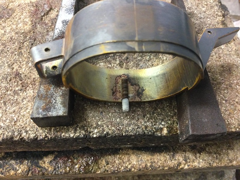 Possibly two studs per fitting would give better support, but it's done now. A flat was filed on the stud to give a more secure bond and stop it rolling around under the blowtorch. Solder was applied in two lengths of thin wire either side of the stud. If not done this way, the melting solder is likely to push the stud out of position. Also note the 'business end' of the stud is well-covered in Tippex. Without this, silver solder has a nasty habit of flowing along threads by capillary action -not a good thing. Into the Citric bath and it should be nice and clean tomorrow, ready to mark and drill the hole in the skin for the stud. While I'm at it, I can bore the ¾" dia hole for the top end of the through-tank conduit which takes the injector feed pipes. I forgot to do this while I was doing all the other drilling and tapping.  |
|
Gary L
Elder Statesman
Posts: 1,208
|
Post by Gary L on Dec 13, 2021 18:24:46 GMT
We left the last posting havimg realised that I forgot to bore the hole in each tank upper skin that takes the through-pipe conduit through which the pipes to the top feeds pass. Boring was a straightforward job and has already been covered with the lower skins. (NB these pipes are not included in the Adams drawing.) However I hadn't done anything about preparing the tubes that will fill the bored holes, so it is time to deal with those. Plan A was just to pass a suitable length of ¾" OD copper tube through, once the tanks were soldered up, and simply solder them in place and trim off the ends. That might indeed be perfectly fine, but soft solder is not very strong, and the slightest tendency of the tanks to 'pant' (e.g. by someone pressing hard on the skin during a moving operation) might cause the joint to fail. I don't know how likely this is, but it seems a good idea to reinforce the joints in some way. I think the main risk is pressure from outside; pressure from within is unlikely verging on impossible. A shoulder in each end of the pipe should be sufficient to add mechanical strength to the structure, without relying on the soft-solder, while also increasing the surface area of the soldered joint. Except that the pipes don't really have enough wall thickness for this to be a sound proposition. So I decided to silver-solder a collar on the pipes, top and bottom instead. I had some copper pipe of the right diameter in stock, so it just entailed parting off 4 slices 5/32" wide- too simple to say any more about it! (If you want to make proper flanges, then why not... I didn't have any suitable material in stock.) That done, the ends of the two pipes could be dressed in the lathe, and the collars squeezed into place (they had to be skimmed internally, so were deliberately made a tight fit). A further, slacker ring is also needed, to press the collars into position:  It is important that all is kept reasonably square ( exactly square would be even better, though any inaccuracy will be hidden). Luckily, as you can see, the pipe fitted snugly into my second-biggest E32 collet, and the drill chuck in the tailstock gave a nice square face and a gentle pressure. So we end up like this:  Then, after fluxing and adding some solder rings, the pipes could be stood on end, ready for heating:  NB. NB. Don't heat the joint directly if you do it this way. The two ends of the solder wire will ball up and run away from where they need to go before the joint gets hot enough for the solder to flash through. Better to apply the flame just above the joint; conduction will do the rest. Once the solder has flashed you can heat the joint directly to be sure of getting decent penetration, though for this job it hardly matters, so long as the collars are stuck on reasonably firmly. Then the collars need to be added to the other end of each pipe. Not quite so easy, because a collet can't be used (think about it), but the 4-jaw SC chuck was adequate. (I don't like turning copper tube in ordinary chucks like this, it is too easy to squeeze it out of shape. If it was very critical I would probably have inserted a plug in the end of the tube.) Then press on the collars as before, checking that the distance between the outer faces is never more than the corresponding dimension of the tank framing (which in this case is 6.25"). I left the lower pipe ends a little over-long, this can be trimmed off when all the tank soldering is finished:  It goes without saying (?) that these pipes must be inserted before the tank skins are finally screwed on and soldered up! |
|
Gary L
Elder Statesman
Posts: 1,208
|
Post by Gary L on Dec 15, 2021 1:51:22 GMT
I think I've done everything, and made everything needed for the Pannier Tanks, so now it is time to stick everything together with solder. I admit to a lot of trepidation, because with screwed and soldered construction they will be very hard to dismantle if any rectification is needed. Anyway, here goes, starting with the Framework. First step is to dismantle the framing parts and 'tin' both faces of every joint. ('Tinning' just means applying a thin coat of solder). This is time-consuming, but the only way to be sure that the solder will fully penetrate the crevices:  Yes, it looks very messy, but it will clean up. As you can see I am using ordinary plumbers lead-free solder; partly because "it was there," and partly because it melts at a slightly higher temperature than ordinary lead-tin solder. This should reduce the prospect of anything going wrong later, when reheating it all to attach the skins. (I plan to use lead-tin solder paint for that, which is self-tinning, but I'm open to advice and suggestions.) The solder appears to be cored, but the flux content certainly isn't enough on its own. Bakers Fluid* seems to give the best results, despite the messy appearance, which is mostly caused by char from the stick I use to apply it. (A brush would be better, but mine lose all their bristles withing minutes). The aim with this tinning is to just 'plate' the joining faces with enough solder to colour them grey. Any more than that, and these close-fitting joints won't fit together! (In the ordinary way, you would be more generous, and apply enough solder to make the joint by 'sweating' the parts together, but that isn't practical here.) I experimented with paste flux incidentally, but the solder didn't flatten out half so well as with the liquid. (* I see the label on the bottle calls it "Stay Clean" flux. Maybe the recipe is different, but it seems very like Bakers to me!) Any excess solder needs to be wiped off hot, or scraped off cold. When I was nearly finished, I discovered (as you do) that tapping the part on a forge brick worked just as well and was much quicker...  Here the tinned and scraped parts are being reassembled. The upper tool is a normal three-cornered scraper. The lower one is a chisel, but made with one side flat like a carpenter's chisel, and kept sharp. I find this a much more useful tool than a conventional cold chisel. Then the whole caboodle is screwed up tight, and carefully checked for squareness and straightness:  And as a final precaution, the skins are positioned with a few screws, enough to check that all the holes still line up perfectly:   Only then did I reckon it was safe to remove the skins and heat the whole frame, adding some extra solder (and flux of course) at every joint. It is quite important to apply the heat evenly, working slowly along all three bars together from one end of the frame to the other. If not, there is a risk that parts will expand out of step with each other, and the frame might not still be square and straight when it cools down. "Here's one I made earlier":  It isn't very neat or pretty, but nobody will see any of it. |
|
|
|
Post by martyn1936 on Jan 3, 2022 10:51:58 GMT
Happy New Year Gary and thank you for your thread it has been a great help to me with my 1501. I am now starting on the back-head fittings and the next one on the list is the lubricator steam valve. The Adams design looks a bit clumsy compared to yours as it is 3/4" deep and yours looks much thinner and with more shape to it. Did you make yours to a different design?
Martyn
|
|
Gary L
Elder Statesman
Posts: 1,208
|
Post by Gary L on Jan 4, 2022 1:24:16 GMT
Happy New Year Gary and thank you for your thread it has been a great help to me with my 1501. I am now starting on the back-head fittings and the next one on the list is the lubricator steam valve. The Adams design looks a bit clumsy compared to yours as it is 3/4" deep and yours looks much thinner and with more shape to it. Did you make yours to a different design? Martyn Hi Martyn Yes indeed, the Adams lubricator layout is unsatisfactory for a variety of reasons. Indeed his whole backhead layout is pretty poor in my view. I’m not going to say mine is better, (because I haven’t tried it yet of course!) but at least I don’t think it will be any worse. I have no experience with hydrostatic lubricators, but that is what the prototype has, so that is what I wanted, but I relied heavily on remarks from others on this forum, particularly Julian. WRT to the valve that I think you mean, internally it is pretty close to Adams’s design (despite the foregoing!) but possibly a little smaller (I forget). But it was feasible to make the outside look considerably less clumsy by paring away unnecessary metal. I was limited by the tappings on the boiler mounting that were already in place. In an ideal world, it would have been nice to represent the design of the prototype, but that was altogether too difficult, as the full-size version works in a different way, and its ‘envelope’ in scaled form is impossibly small, at least for me. HTH Gary |
|
Gary L
Elder Statesman
Posts: 1,208
|
Post by Gary L on Jan 6, 2022 0:24:36 GMT
Paddington's Progress has been glacial lately, here at Gary Towers. Partly because of seasonal shenanigans, and partly out of sheer funk! The Pannier Tanks are the biggest soldering job I have ever attempted by a country mile, and they represent a considerable amount of materials and effort, so I don't want to end up spoiling them with distortion caused by inexperience and/or carelessness. As mentioned before, my plan is to use solder paint for all the (many) joints to avoid having to pre-tin everything, but this creates a problem of its own. Left exposed too long, the flux content (Bakers, I gather) will dry out and (probably) react with the brass and become ineffective (comments from experts welcome!) Anyway, to give me the best possible chance, the final pre-assembly and the heating will all need to be done in one session, and it could be a long one! So I'm waiting for a clear whole day in my calendar to tackle the first tank and allow for any hiccups. I've done a pre-pre-assembly dry run of both tanks to try and spot any last-minute glitches:  There are around 60 8BA tapped holes on each tank. Oh dear, I've only got 30 or so ¼" brass CSKs in stock, could have sworn I had more than that... glad I didn't find that out on the Big Day... There is a gap at the horizontal seam between top and bottom plates. Not a problem but it will need to be filled; do I have enough 40/60 solder? Who can say, but better too much than too little so that's another eBay order... And so it goes on... In passing, my aim is to use lead (i.e. body solder or 40/60 tin/lead) for the bulk of the filling. I doubt if I am skilled enough to eliminate plastic fillers entirely, but if there are seams to be filled with 2-pack, the gap needs to be a decent width. A narrow crack will soon lose adhesion as expansion and contraction takes its toll. Then there is the question of heating. This is a big mass of brass, of many different thicknesses, and it needs to be heated uniformly, which is not easy with a propane torch, even a large one. A contributor in another thread suggested pre-heating in a domestic oven. Even if I could get that past the Domestic Authorities, It would require an enormous oven, because these tanks are 22½" long! Done the workshop way, it requires a pretty large forge too, and it was soon clear that didn't have enough firebricks. The old ones were getting past it anyway, so that involved a 60-mile round trip to Brislington to buy some new ones. (The bricks are not exorbitant, but the carriage costs more than the product!) Naturally I checked the supplier's website for holiday dates and opening hours before departing.On arrival the shop was shut and dark, but the office was open. Duly masked up, I rang the bell, in bad humour as you might imagine. A nice young lady answered the door: Moving swiftly on, here are the nice new firebricks, roughly arranged to take a tank. I will warm them up with the torch first, then place the tank inside the trough, and hopefully the bricks will retain heat between passes of the torch so that the temperature is as uniform as possible, and when the soldering is done, the cooling will also be slow and steady. A blanket or some foil over the top will help:  These are normal clay firebricks BTW. The previous ones were vermiculite, which is nice and light, but very messy, shedding particles all the time (until encrusted with flux at least. The old flux makes a different kind of mess on a job, given half a chance) Solder paint contains Bakers Fluid I believe, and Bakers has a bad reputation for giving off corrosive vapour which causes surface rusting on steel; not desirable in any workshop, so many people prefer to use it out of doors. I don't get much trouble from that, because I have a redundant cooker hood installed over my soldering station:  It has to exhaust outside though, through the ducting that can be seen in the photo. The recycling type of hood wouldn't do much good. This one gives a decent amount of suck on the Max setting; it also takes away nasty flux fumes when silver-soldering, and makes a handy shelf for lightweight items, gloves, etc above it. Cost was zero, because the kitchen was being replaced. I anticipate that I will need to brush extra Bakers onto the job, and also add extra solder round the edges to be sure of no leaks. Solder paint is great stuff for a neat join with minimum staining, but I always get a suspicion that it might not give a completely filled join. Maybe I worry too much?
|
|
|
|
Post by RGR 60130 on Jan 6, 2022 10:33:41 GMT
Quote "Then there is the question of heating. This is a big mass of brass, of many different thicknesses, and it needs to be heated uniformly, which is not easy with a propane torch, even a large one. A contributor in another thread suggested pre-heating in a domestic oven. Even if I could get that past the Domestic Authorities, It would require an enormous oven, because these tanks are 22½" long!" Gary, I've always used the kitchen over for tender bodies. I built a 4 sided box out of that multi-layer foil insulation stuff. An hour at 220C does the trick. Your tanks are probably much cleaner than a lot of the meat tins that go into ovens all over the country on a Sunday and Christmas without question. The tender body shown below is just over 26" long. Reg  DSC01953 DSC01953 by reg.rossiter, on Flickr  DSC01894 DSC01894 by reg.rossiter, on Flickr |
|
Gary L
Elder Statesman
Posts: 1,208
|
Post by Gary L on Jan 6, 2022 17:25:40 GMT
Quote "Then there is the question of heating. This is a big mass of brass, of many different thicknesses, and it needs to be heated uniformly, which is not easy with a propane torch, even a large one. A contributor in another thread suggested pre-heating in a domestic oven. Even if I could get that past the Domestic Authorities, It would require an enormous oven, because these tanks are 22½" long!" Gary, I've always used the kitchen over for tender bodies. I built a 4 sided box out of that multi-layer foil insulation stuff. An hour at 220C does the trick. Your tanks are probably much cleaner than a lot of the meat tins that go into ovens all over the country on a Sunday and Christmas without question. The tender body shown below is just over 26" long. Reg You're a brave man Reg! But an ingenious solution. I don't think I am brave enough, especially since only yesterday The Oven was deep-cleaned by a professional at huge expense... Gary |
|
|
|
Post by RGR 60130 on Jan 6, 2022 17:35:13 GMT
The perfect time to do it then! You don't want your lovely clean brass tanks covered in oven gunge, do you?
Good luck
Reg
|
|
|
|
Post by martyn1936 on Jan 6, 2022 18:23:03 GMT
Hi Gary, thank you for the feedback on the lubricator steam valve. I have now made it more or less to the Adam's design but as you suggested improved the outline a little bit. Being a novice with regards to displacement lubricators I still have some unanswered questions in my mind. Firstly are the dimensions of his nozzles correct? He shows them as a press fit but I intend to glue mine in with nutlock so that they can be changed more easily if I have to experiment. Secondly why has he fitted a spring loaded check valve in line? Surely when the lubricator is working the pressure difference across it will be quite small and I am concerned that it might not be enough to overcome the spring etc. These are probably silly questions but I want to understand why I am doing it his way.
I am about to begin making the fire-hole door which is straightforward and I have started thinking about the steam brake valve. The Adam's drawing shows a simple steam valve I want to build a combined steam and vacuum brake valve looking more prototypical. The valve on your back-head is a casting but is it a combined steam and vacuum valve? If it is did you follow a published design? And of course which design and sourced from where?.
Sorry these are all questions but at the moment I have many more questions than answers.
Martyn
|
|
Gary L
Elder Statesman
Posts: 1,208
|
Post by Gary L on Jan 6, 2022 23:55:48 GMT
Hi Gary, thank you for the feedback on the lubricator steam valve. I have now made it more or less to the Adam's design but as you suggested improved the outline a little bit. Being a novice with regards to displacement lubricators I still have some unanswered questions in my mind. Firstly are the dimensions of his nozzles correct? He shows them as a press fit but I intend to glue mine in with nutlock so that they can be changed more easily if I have to experiment. Secondly why has he fitted a spring loaded check valve in line? Surely when the lubricator is working the pressure difference across it will be quite small and I am concerned that it might not be enough to overcome the spring etc. These are probably silly questions but I want to understand why I am doing it his way. I am about to begin making the fire-hole door which is straightforward and I have started thinking about the steam brake valve. The Adam's drawing shows a simple steam valve I want to build a combined steam and vacuum brake valve looking more prototypical. The valve on your back-head is a casting but is it a combined steam and vacuum valve? If it is did you follow a published design? And of course which design and sourced from where?. Sorry these are all questions but at the moment I have many more questions than answers. Martyn Hi Martyn WRT displacement lubricators, I am no expert. In fact I'm a complete novice, and there are much more experienced people on here. I haven't yet tested my arrangement, so following me isn't necessarily the right way to go! However the most obvious faults with the Adams design (IMO) are (1) the pipes through the boiler- why? They take up backhead space and get in the way of more prototypical fittings. (Run them under the cladding, like the prototype does). (2) The tank has the filler in an awkward place that will get covered in coal dust. Why not fill it from a suitable tube and valve from underneath? The non-return valves are a vexed issue. ITSM that you really, really don't want any risk of a back flow in the oil line, and there is no disadvantage to having them so why not? In fact redundancy might be good idea, just in case. A fine nozzle is needed where the oil pipe joins the steam pipe. I couldn't be bothered to make a lubricator body, so I fitted one from Polly, which is visually slightly more prototypical than most others. The nozzle sizes were close to, or exactly what Julian recommends, so I saw no need to change them, and in any case the valves are there to reduce the flow if it is too great. Remember that it is hydraulic pressure, not steam pressure that makes a Hydrostatic lubricator work, so the pressure differential could be considerable at times. My steam brake valve is one of Adam Cro's excellent products, but as standard the vacuum side is very simple, and works in tandem with the steam brake*. I had to adapt it somewhat to provide a 'lap' function; I hope it will work, but won't know till I have it in steam! In retrospect, being a scale model, it looks rather tiny on a backhead when all the other fittings are distinctly (and necessarily) "coarse scale," but that isn't Adam's fault. (What I would really have liked is a working model of the original, which would automatically apply the loco (steam) brake if the vacuum line was parted by a breakaway, but that would have been a real challenge!) *As an aside, I have fed the steam brake side of the valve through a shut-off cock, because it is very unlikely I would ever want to use the steam brake in earnest, it is just nice to know that I could if I wanted to. HTH Gary |
|


 )
)

