|
|
Post by springcrocus on Oct 15, 2022 9:15:33 GMT
Boiler continuedLast week we soldered all the stays on the other side of the firebox but it was just a repeat of the previous weeks work. I didn't bother to write it up separately because there was nothing different and it would have just felt like boasting - look how clever we are - and that's not what this thread is about, it's about sharing. The one photo that might be of interest is the boiler in the hearth just before lighting the torches. The cyclone burner was used to heat the inside of the firebox and the normal burner fed heat into the water space from the back.  I had also previously made a steel plate to cover the tube ends and give them a bit of protection from the fierce heat. The thin wall of these makes them more vunerable to overheating, leading to a damaged joint. A length of M6 stainless steel studding passes through one of the flues to keep it in place and the rod can be drawn out through the firehole if the nut gets jammed at the firebox end.  This week, we revisited two stays that didn't look quite good enough. Rather than risk having a leak later on, it was worth resoldering now whilst access was much easier. Then we fitted all the crown stays, which replace the girder stays that DY had specified. I made these from 3/16" diameter copper rod because rivets of the required length were not available. After parting off, one end of each was gently hammered over to form a mushroom head. A close-fitting washer protects the collet and limits the spread of the copper.  This is how they look inside the firebox. The stay spacing is greater than on the sides because the larger stay sizes allow for a larger grid pattern but the dimensions used reflect those in the Australian boiler code for these sizes of material and operating pressure. They are also superior to the girder stays because of the stronger through-joint compared to the butt-joint of a girder stay.  One unusual thing were the four additional stays that I've added around the firehole. I wasn't happy with what was shown on the drawing and these additional stays perform a dual function. These are 3/16" diameter copper rivets that have had the heads thinned down, then cut to length and the core drilled and tapped 8BA and will be used to fix the firehole door panel to. The unusual bit is that I've opted to solder them to the firebox now, rather than when the backhead goes on because they would have been extrmely difficult to get to later on. This next photo shows them in place.  With it all cleaned up, here is a view through the crown before the backhead goes on. The angled stays are to allow enough room for the regulator tube to pass freely through, with the blower and Westinghouse pump stays passing by on the outward sides. Also, the firehole door fixing points can be more clearly seen.  And this final picture shows the backhead temporarily in place. The four backhead rivets are nice and soft so easy to align. Once the backhead is soldered up, they will be trimmed back to flush and the thread re-tapped. By doing it this way, I don't have the risk of trying to drill a blind hole in the rivet and/or breaking a tap in there at the last moment.  This may not be how the old-school boiler-makers would have done things but that doesn't mean we are doing it wrong, just differently. These cadmium-free solders are completely different to the old stuff and new methods can be adopted to suit the new materials. Regards, Steve
|
|
|
|
Post by springcrocus on Oct 20, 2022 20:58:48 GMT
ManifoldI have made the manifold as an assembly of eleven parts, all turned from Colphos bronze and soldered together with 1/2mm diameter silver solder wire. I started by turning the base of the main stem from 5/8" diameter material and threading it 3/8" x 32tpi to fit the manifold bush on top of the boiler. It was then screwed into a mandrel and all the other operations done in sequence, the first of these being to mill the square upper section to size. 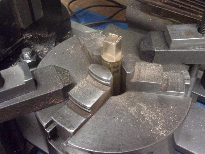 The front and back centre ports were made as a single piece, turned down to 1/4" diameter and then drilled and tapped their respective sizes. A 1/4" diameter hole was drilled through the block and the front and back ports soldered in. Next, the two arms were turned, along with the outer valve stems and two half-way ports which are screwed into the crosspipes. These parts were also soldered together. Meanwhile, the centre block has been cross-drilled and counterbored ready for the crosspipes. 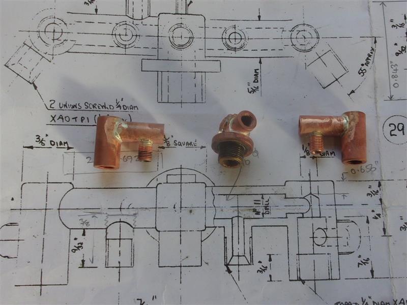 It was quite fiddly getting everything aligned but screwing the taps back in helped enormously.  Lots more flux, including on existing joints, and the main body parts are joined together.  With it all cleaned up, the single outlet on the top left arm had to be drilled and tapped. It was getting a little more difficult to hold in the vice, multiple packing pieces needed for the job.  The two outlets for the injectors needed to be set at about 35 degrees so, for me, the easiest way to hold the work was by clamping it to the tilting table.  The last few outlets were soldered in and this is how it looks after cleaning up. 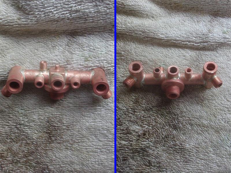 Just the valve assemblies to make for the outer ends and a dummy whistle for the top and this is complete. Regards, Steve
|
|
|
|
Post by springcrocus on Oct 22, 2022 10:00:41 GMT
Gauge glass bushesIt's impossible to make the gauge glass arrangement look anything like the prototype and still function properly and the backhead of the model only bears a passing resemblance to the full-sized "Calbourne", anyway. The upper bush is the one that causes the problems and DY drew up a flimsy bracket with a couple of bits of tube soldered together that looks awful. My effort doesn't look any better but is a fair bit stronger.  To allow for replacement of the complete gauge glass assembly I made a bush from hexagon bronze, drilled and tapped 1/4" x 40 tpi the same as the fixed lower bush, and soldered a short length of 1/4" diameter thick-walled copper tube to it with 40% (high temp) silver solder. The backhead was clamped to an angle plate and a matching hole made with a 3/16" diameter slot drill. Then the upper bush assembly was set in the hole using a spacing gauge to set both height and orientation.  I've chosen hexagon material because I will be able to support the bush with a spanner when I tighten up the top fitting. The lower bush has also been soldered in with 40% solder, as will be the fitting-to-backhead joint. That way, I should have no problems when it comes to closing the boiler.  Although it looks a bit silly at the moment, once the cab front is in place, it will blend into the background. The drawing shows the position of the upper bush suspended in mid-air.  This is the completed assembly set into the boiler. A small notch has been cut to allow the backhead to sit in the correct position but there is still plenty of flange available for soldering at final assembly.  Wilf came over yesterday and we able to get the front tubeplate soldered into position. It took a little while to align the tubes because I missed a trick when I bored the barrel. I should have relieved the front section by an extra five thou and this would have allowed the tubeplate to wobble about a bit easier. Lesson learned for next time. Happily, we've had a good melt.  We did have one minor hiccup but more on that next week. A couple more sessions should see this boiler finished. Regards, Steve
|
|
|
|
Post by springcrocus on Nov 6, 2022 16:28:16 GMT
Wilf and I have sorted the small hiccup with the boiler and have now soldered the backhead into place, although there are a couple of rivets that we need to visit again. I will write this up when we've fixed those and done the foundation ring, hopefully finishing it next week.
Inner dome Don Young designed the inner dome to allow space for a Stroudley-type regulator but I am using a different type of regulator and don't require so much space in the dome. Wilf suggested turning the dome into a filler cap to allow quick and easy filling of the boiler so that's what I've done. This is my sketch of the inner dome alongside the drawn version and it can be seen that I've lowered the top plate to create a reservoir for filling. 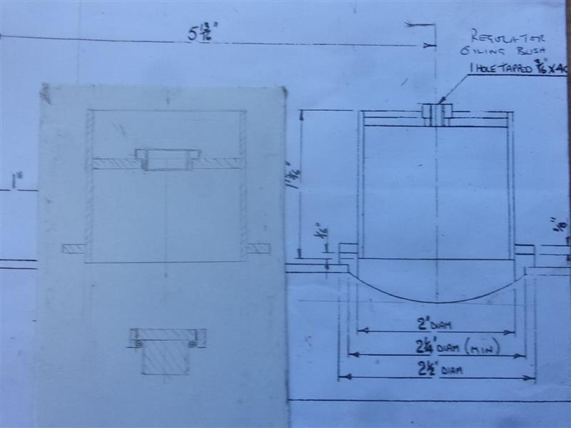 The outer ring was made from bronze at the same time as the dome flange was made and needed silver-soldering to a length of 2" dia copper tube. I couldn't find any amongst colleagues and the only (sensibly-priced) online supplier wanted to sell a minimum of 6" length so I used a piece of brass tube instead. The tube was machined internally at the top, just enough to create a lip for the top plate to rest on and the O/D at the other end skimmed for 3/16" length to take the ring. 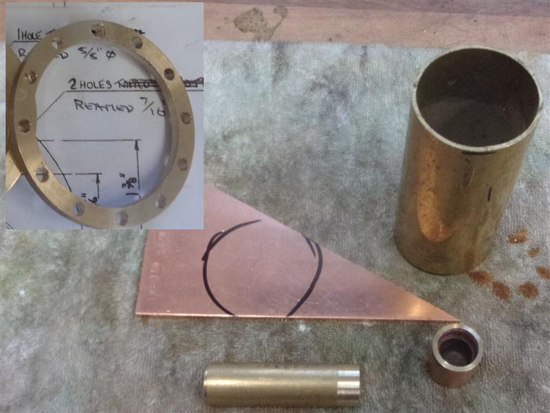 The top plate was made from an offcut of 1/8" copper sheet and the bush from 3/4" diameter brass. I've used M14 x 1 for the thread because it's nice and big and I have a matching tap and die. After drilling a 10mm diameter hole in the copper offcut, it was mounted on a mandrel, sandwiched between two large penny washers and turned to a nice fit in the bore of the dome. Then the bore was taken out to 5/8" diameter for the bush. 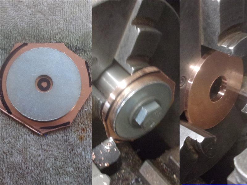 The ring was silver-soldered first, the job cleaned up and pickled, then the plate and the bush both soldered at the same time.  The bung was turned and threaded M14 x 1mm by about 3/8" long, then parted off with a 1/8" long head. I wanted a shroud to enclose the "O" ring and it was easier to solder a piece of fabricated tube to the head of the bung, rather than try to undercut the head of the bung. A piece of 7/8" diameter brass was drilled and bored to be a snug fit over the head and soldered into place. To finish, a 1/8" slot was milled across the head and a piece of flat brass bar soldered in to make a handle. 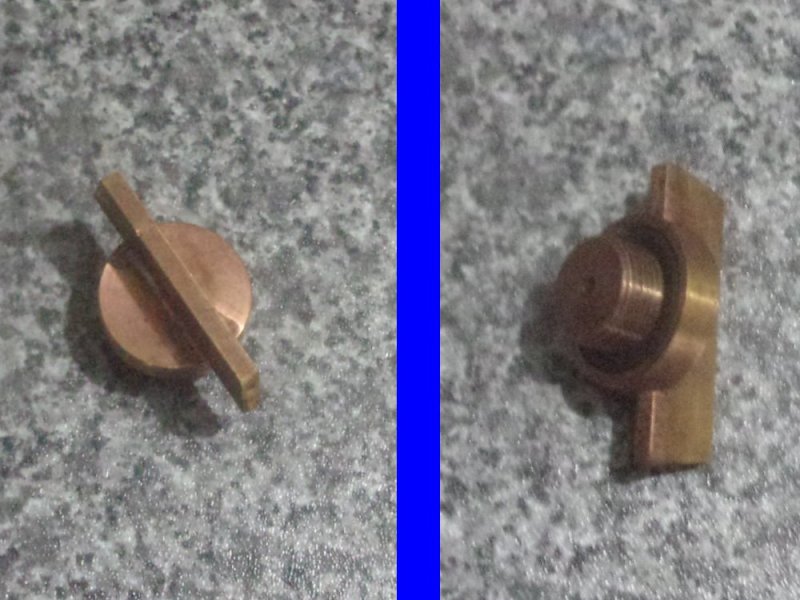 When screwed down, the collar completely encloses the "O" ring as it passes over the head of the bush. I will check with the boiler inspector to see if he wants some form of locking arrangement to ensure the bung cannot be removed while the boiler is pressurised.  It's also a great opportunity to use up another dozen of those 4BA cap screws that came from Whistons about fifty years ago. Some of the older members may remember that firm. Regards, Steve |
|
mbrown
Elder Statesman
  
Posts: 1,786
|
Post by mbrown on Nov 6, 2022 18:02:15 GMT
Oh dear.... I used Whiston's for many years, but it comes as a bit of a shock to realise that this makes me one of the "older members"! I suppose it is true, but I continue to resist anno domini...
Whiston's demise was a great loss to the ME world.
Loving your boiler build - smashing work.
Malcolm
|
|
|
|
Post by ettingtonliam on Nov 7, 2022 3:12:30 GMT
Wasn't Whistons catch line 'Seen my Cat'?
|
|
jma1009
Elder Statesman
  
Posts: 5,917
|
Post by jma1009 on Nov 7, 2022 19:48:48 GMT
Hi Steve,
I don't think that the inner dome should be of brass tube, nor it's bush on the top. It's not a dezinctification issue per se, but how brass is inferior as part of a pressure vessel such as the inner dome tube, and a phos bronze bush is going to be superior to brass especially after silver soldering of both. Silver soldering can do odd things to brass when compared to copper and phos bronze. I personally wouldn't want to go anywhere near a miniature loco in steam with a brass inner dome tube!
Definitely a bad mistake in my opinion in all respects.
I also don't like the top water gauge 'elbow' with copper tube with a lump of hex for a spanner. Setting aside the unsuitability of using copper pipe in such a situation, what makes you think that a spanner has to fit a bit of unsightly hex? A spanner can fit a bit of square rounded off if you must go down the copper pipe route instead of a proper elbow made out of solid phos bronze.
You will have some fun with the foundation ring I expect.
Good luck.
Cheers,
Julian
|
|
|
|
Post by springcrocus on Nov 8, 2022 8:12:22 GMT
Hi Steve, I don't think that the inner dome should be of brass tube, nor it's bush on the top. It's not a dezinctification issue per se, but how brass is inferior as part of a pressure vessel such as the inner dome tube, and a phos bronze bush is going to be superior to brass especially after silver soldering of both. Silver soldering can do odd things to brass when compared to copper and phos bronze. I personally wouldn't want to go anywhere near a miniature loco in steam with a brass inner dome tube! Cheers, Julian Fair comment! Although I would be interested in the opinion of others considering it is a bolt-on item, not an integral part of the boiler, and can be readily removed for inspection. It may be that the boiler inspector will reject it anyway but it can be tested to the full 2x shell-test pressure. In the meantime, however, if anyone has a piece of 2" diameter copper tube by two inches long that they would like to donate to the cause (I will pay the postage, of course), then it can easily be remade. Don Young drew the item as an elbow made from copper tube: who am I to argue? Anyway, that part is a done deal, the boiler inspector is happy and the backhead is fixed. The hexagon material is phosphor bronze. Thank you   Regards, Steve |
|
|
|
Post by flyingfox on Nov 8, 2022 13:03:17 GMT
Greetings Steve, the use of brass in boiler construction is not permitted, no matter (in your case) so obviously well made.
Brass is unstable & liable to decomposition in use as part of a boiler.
Regards
Brian B
|
|
jma1009
Elder Statesman
  
Posts: 5,917
|
Post by jma1009 on Nov 8, 2022 23:01:05 GMT
Macc Models do a 2" length of 2" dia 10 swg copper tube for £13.68.
|
|
|
|
Post by ettingtonliam on Nov 9, 2022 7:30:16 GMT
Greetings Steve, the use of brass in boiler construction is not permitted, no matter (in your case) so obviously well made. Brass is unstable & liable to decomposition in use as part of a boiler. Regards Brian B Yes, I can see that for the boiler shell, but does it also apply to the inner dome which is a separate bolt on fitting well above the waterline? Do fittings class as 'boiler construction'? |
|
|
|
Post by springcrocus on Nov 9, 2022 9:23:04 GMT
Thank you Brian, Richard and Julian for your replies.
This could make an interesting topic for further discussion so I have started a dedicated thread that you gentlemen, and others, might like to contribute to. Meanwhile, I have nearly finished wrinting up the firehole door plate and fittings, which will be posted a bit later on.
Regards, Steve
|
|
|
|
Post by springcrocus on Nov 11, 2022 9:34:55 GMT
Firehole doorsThere's not much to say about these, other than I've redesigned the backplate to make it fit to the extra stays that I put in the backhead. The two bosses are silver-soldered to the tails of the plate and the door runners are temporarily fixed with nuts and bolts 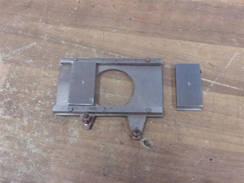 The original design has the doors running on the outside of the door bars and lipped over the back but, because of space constraints, I've made mine to run inside the bars in channels. The doors are solid at the moment but I might hollow them out, more like the protoytpe. The linkages are cut from 16 swg mild steel sheet. 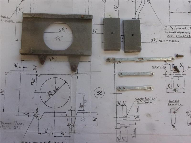 This is the assembled mechanism using 3/32" diameter rivets for pivots. The screws that fix to the doors can be locked by studs from the other side. 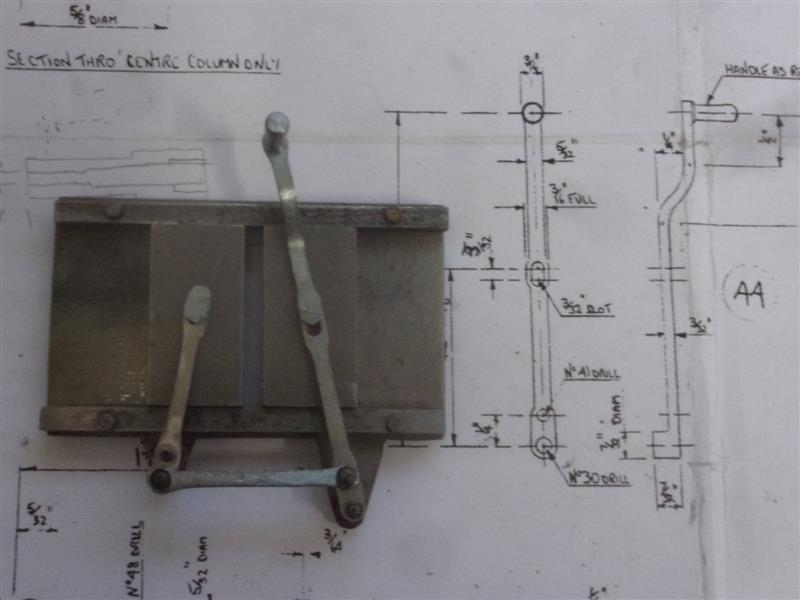 Not very interesting but another job ticked off. Regards, Steve
|
|
|
|
Post by ettingtonliam on Nov 11, 2022 12:39:59 GMT
Do you think coal dust will build up in the lower channel and make the doors jam, or is the channel open at the bottom?
|
|
|
|
Post by springcrocus on Nov 11, 2022 15:41:35 GMT
Do you think coal dust will build up in the lower channel and make the doors jam, or is the channel open at the bottom? It isn't but it soon will be! Thanks, Richard, for that sage advice.
Regards, Steve
|
|
|
|
Post by ettingtonliam on Nov 11, 2022 16:13:17 GMT
Glad to have been of help.
|
|
|
|
Post by springcrocus on Nov 12, 2022 23:22:27 GMT
Boiler continued.Last week, Wilf and I fixed a couple of dodgy stays, then went on to fit the backhead. Prior to that, I had taken the advice of the boiler inspector and dressed back the pipe end leading to water gauge top fitting.  Bushes, firehole and most of the stays went without a hitch and there was a small area at the top of the wrapper that needed resoldering which didn't come to light until the boiler had been thorougly cleaned. During the heat-up, the solder resting on the lip fell off and I had to resort to the dab-it-in method but this is generally not very successful for amateurs like me and Wilf. This week, we tidied up the backhead, then gave it another session in the pickle while we had lunch. 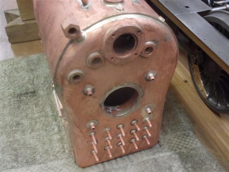 After lunch, we started on the foundation ring. I had made all the parts earlier in the week so it was just a case of fluxing up, setting them in place and teasing the wrapper for a nice fit. I have some flat silver solder that had been given to me and was told it was Easyflo, so pretty similar to our usual stuff. Here is the set-up in the hearth.  The foundation ring pieces are set just below the level of the outer wrapper so it's like a shallow moat all the way round. There's actually quite a lot of solder there because the stuff is 5mm wide x 1mm thick. I had filed a chamfer on the outer edges of the four pieces to encourage the solder to flow down the gaps. Here's another view from further back showing how much effort we go to setting things up. This is all to conserve heat but also keep it mostly where it's needed.  We started with two normal burners but kept blowing each other's torch out so Wilf went back to the cyclone burner and worked inside the box while I heated the outside. Once we were nearly up to temperature, we concentrated our efforts at a single point on one of the sides, then slowly worked our way round chasing the melting solder until we were back at the start. That was it, finished.  It looked like a pretty good melt but it's always hard to tell until the thing has cooled and been cleared up. Immediately after that last picture was taken, a further block was placed on top to slow down any localised cooling. Wilf left soon after this and I allowed it to cool for about 45 minutes before washing and pickling. This is the result and it can be seen that it's gone well. All the solder has vanished instead of puddling on top and all the gaps are a lovely, shiny silver.  It's out of view of the camera but there appears to be a very small area at the back that may not have taken but until I've made the blanking plugs, I can't test it to find out. We may add some extra solder there, anyway, but it looks like we will be heading for a shell test in the very near future. Regards, Steve
|
|
uuu
Elder Statesman
   your message here...
Posts: 2,857
|
Post by uuu on Nov 13, 2022 8:25:35 GMT
I really enjoyed that. It was so satisfying to watch as the solder just sucked itself in.
A key point, I think, is the care with which Steve prepares the work. The pieces fit beautifully - there are no gaps that the solder struggles to bridge. It seems to be a feature of this cadmium-free solder, that it doesn't form fillets like the old stuff - it needs much tighter gaps, and will even flow into a clamped joint.
Wilf
|
|
|
|
Post by islandsteamer59 on Nov 13, 2022 22:28:31 GMT
Wilf and I have sorted the small hiccup with the boiler and have now soldered the backhead into place, although there are a couple of rivets that we need to visit again. I will write this up when we've fixed those and done the foundation ring, hopefully finishing it next week.
Inner dome Don Young designed the inner dome to allow space for a Stroudley-type regulator but I am using a different type of regulator and don't require so much space in the dome. Wilf suggested turning the dome into a filler cap to allow quick and easy filling of the boiler so that's what I've done. This is my sketch of the inner dome alongside the drawn version and it can be seen that I've lowered the top plate to create a reservoir for filling.  The outer ring was made from bronze at the same time as the dome flange was made and needed silver-soldering to a length of 2" dia copper tube. I couldn't find any amongst colleagues and the only (sensibly-priced) online supplier wanted to sell a minimum of 6" length so I used a piece of brass tube instead. The tube was machined internally at the top, just enough to create a lip for the top plate to rest on and the O/D at the other end skimmed for 3/16" length to take the ring.  The top plate was made from an offcut of 1/8" copper sheet and the bush from 3/4" diameter brass. I've used M14 x 1 for the thread because it's nice and big and I have a matching tap and die. After drilling a 10mm diameter hole in the copper offcut, it was mounted on a mandrel, sandwiched between two large penny washers and turned to a nice fit in the bore of the dome. Then the bore was taken out to 5/8" diameter for the bush.  The ring was silver-soldered first, the job cleaned up and pickled, then the plate and the bush both soldered at the same time.  The bung was turned and threaded M14 x 1mm by about 3/8" long, then parted off with a 1/8" long head. I wanted a shroud to enclose the "O" ring and it was easier to solder a piece of fabricated tube to the head of the bung, rather than try to undercut the head of the bung. A piece of 7/8" diameter brass was drilled and bored to be a snug fit over the head and soldered into place. To finish, a 1/8" slot was milled across the head and a piece of flat brass bar soldered in to make a handle.  When screwed down, the collar completely encloses the "O" ring as it passes over the head of the bush. I will check with the boiler inspector to see if he wants some form of locking arrangement to ensure the bung cannot be removed while the boiler is pressurised.  It's also a great opportunity to use up another dozen of those 4BA cap screws that came from Whistons about fifty years ago. Some of the older members may remember that firm. Regards, Steve |
|
|
|
Post by springcrocus on Nov 18, 2022 22:00:19 GMT
So that's a "No" then, sorry about the dead post just above. First pressure testWe have a boiler. It looked like there was a tiny gap at the back of the foundation ring so we re-soldered that just to be sure of a seal. After cooling and pickling, we bunged up all the bushes and started to pump. We had all the usual weeps from the blanking plugs but once we had got that settled down, we wiped everything dry and took it in stages up to 160 psi. After twenty minutes the pressure was still just over 150psi but everything was bone dry so it was probably leaking back past the pump. 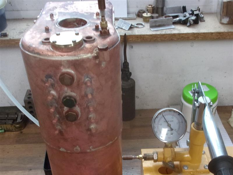  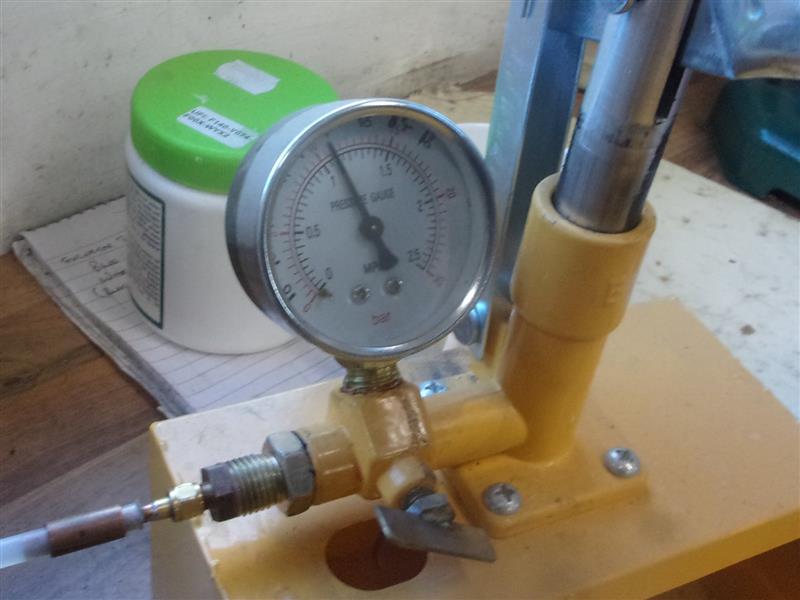 I shall now dress back the crown stays and the extra firehole stays, make it look pretty and arrange to have the shell test done up at Broadfields. Well pleased! Regards, Steve |
|


