|
|
Post by jcsteam on Oct 2, 2021 23:49:50 GMT
Hello everyone, Two weeks ago (11th Sep) with my sons 6th birthday approaching we asked him what he would like for his birthday presents. I was a little taken aback when he said he wanted a ride on train like the ones on the tracks at the clubs. Pausing for thought, and the eager eyes of my partner looking directly at me, I replied saying that they are a lot of money to buy. Too much for a birthday present, to which he replied "no I don't want a bought one, I want daddy to make me one". Well with that gauntlet well and truly thrown down by my 5 year old. What is a man to do but to set about scheming out how to go about building one, and working out how to build one quick, (5 weeks until his birthday) and cheap enough that it is workable, reliable, safe and gives the biggest smile factor in return. I spent the rest of that night until around 1am, sketching out a quick line drawing in my notebook, I settled quickly on a 5" narrow gauge deisel outline. Been easily made from plywood, and concealing the common car battery. Dimensions would be to sweet pea. As that gave me a good guide without having to scale any drawings.  received_561845271905282 received_561845271905282 by Jon Cameron, on Flickr  20210916_175031 20210916_175031 by Jon Cameron, on Flickr So the plan was settled, using chopped down take up bearings for the axleboxes, (which would save a lot of machining and meant I didn't have to spend so long making sure alignment was perfect. Wheels and axles would be to narrow gauge tread profile, CNC wheels and axles been bought if I couldn't machine them properly. Capacity for 2x12v 063 car batteries, which are around the most common and cheapest around. Electronic gear following Colin Edmonsons Scamp components. Using fairly cheap controller, and 500w 24v DC scooter motor, again been able to be picked up relatively cheaply. Steel was going to be whatever I have in my garage that I can make use of. Chain and sprocket drive, for which I already had some of the parts I'd need. The next morning I woke and told my partner Vikki that I could probably build it in time, but it would need XY&Z, at which point she looked at me blank, so I said it'll be this much. She said OK as long as your sure you can do it. Without wanting to commit fully just yet, I told her let me get some of the bits made up this week and see how far I get before we buy anything. So week 1 build;  20210913_174030 20210913_174030 by Jon Cameron, on Flickr  20210914_234628 20210914_234628 by Jon Cameron, on Flickr  20210918_174857 20210918_174857 by Jon Cameron, on Flickr The frame material was cleaned up from the collected steel pile, and cut to size, slightly shorter than sweet pea, at 27.1/2" instead of 31" due to there been a weld on the end of the frame which I didn't want to include. The buffer material also been cut from shorter pieces of the same recovered material. There were then marked up and drilled to make them a pair, using three M6 bolts to secure them together. I cut some angle pieces and machined both sides under the milling cutter to make them 90° angle. The buffers were then clamped to the cross slide of my Myford ML4, to machine both sides at 90° to the top which id filed flat to make a reference point. The corners were then sliced off with a slitting disc in the grinder, and put back under the milling cutter using a tri square against the side of the cross slide and the top edge of the buffer stocks get the 45° angle. One side done, disaster struck on the second side. I felt some resistance in my cross slide handle, and then the heart wrenching moment after turning off the machine. Id stripped the cross slide thread, which for those that don't know is tapped directly into the saddle casting. Cowing into the house that night for tea quite upset and flustered, I told my partner what had happened and thus rendered my beloved ML4 useless. The dial had gone from having 20thou backlash which I was used to working with, to having nearly 60thou just like that, and a really gritty feel when retracting the cross slide. Without a lathe the idea was dead in the water, but by this point we had already told my son that I'd make him a loco for his birthday. So after exhausting all ideas as to what I have at my disposal to fix the ML4. I agreed with Vikki that I should try get the ML7 that I'd bought as a project set up and running, not only would this give me some bench space, it would also mean I had a usable lathe, which I had tooling that I could use. I started on the Saturday morning. By Tuesday I'd got it set up and running accurately to machine parts again, next problem was the chuck, the 3 jaw that came with the ML7 was too small, so I looked at the four jaw on the ML4 and decided to swap it over. It is a bit heath Robinson as the only tap I don't have is a 5/16BSW, guess what the screws are in the chuck...... so I have used M8 cap heads for now, getting our tooling guy at work to skim the heads to the same OD to fit the chuck body holes. It got me away when time is short, and will buy a new back plate and do a proper job in the future. So that was week 1, week 2 next. |
|
|
|
Post by jcsteam on Oct 3, 2021 0:11:56 GMT
Week 2 part1 So after all the issues with the lathe and now been up and running again. I centre popped all the holes to be drilled in the frames and took them into work to drill them on the pillar drill. A tool which I've already said will be my next big investment in the workshop. Within an hour all the holes were drilled with a slowcomb drill then a small pilot drill, followed by a 6mm drill bit.  20210915_174433 20210915_174433 by Jon Cameron, on Flickr As mentioned already the 4 jaw is a bit of a bodge to get me running and able to machine the wheels and other parts.  20210922_013015 20210922_013015 by Jon Cameron, on Flickr Wheel turning could now commence, and was the biggest ask of me I feel as I've never machined wheels up before, but I knew if all else failed I could buy them off the shelf. I started by facing off blanks that are around 100mm dia, these were off cuts from a large shaft at work, I had it cut into slices after I found out it was to be thrown out.  20210922_003410 20210922_003410 by Jon Cameron, on Flickr Once faced off they were drilled out, and reamed to size, adding a chamfer to the hole so the wheels would sit well on the axles and the mandrel for machining.  20210922_004014 20210922_004014 by Jon Cameron, on Flickr  20210922_003923 20210922_003923 by Jon Cameron, on Flickr After the machining ops were done for each wheel in turn I had these four wheel blanks, with the backs faced and a bore running perfectly true with the back face.  20210922_004349 20210922_004349 by Jon Cameron, on Flickr Mounted on a mandrel held in the four jaw, a DTI was setup to measure the movement of the cross slide, the dials not receiving attention during the quick rebuild of the lathe. The wheels OD was turned the same for each wheel blank. Then using the wheel standards I'd printed out, I machined the treads and flanges to rough profile and depth.  20210922_211252 20210922_211252 by Jon Cameron, on Flickr  20210922_225335 20210922_225335 by Jon Cameron, on Flickr  20210923_015600 20210923_015600 by Jon Cameron, on Flickr The tread was the first to be final machined, and the compound slide set over to 3° angle, each wheel was machined at this setting been swapped on the mandrel  20210925_134130 20210925_134130 by Jon Cameron, on Flickr The wheels then had the flange machined with a 20° taper, the flange been rounded over with a file, and the chamfer added to the front of the wheels the same. All four wheels machined within a thou of each other. 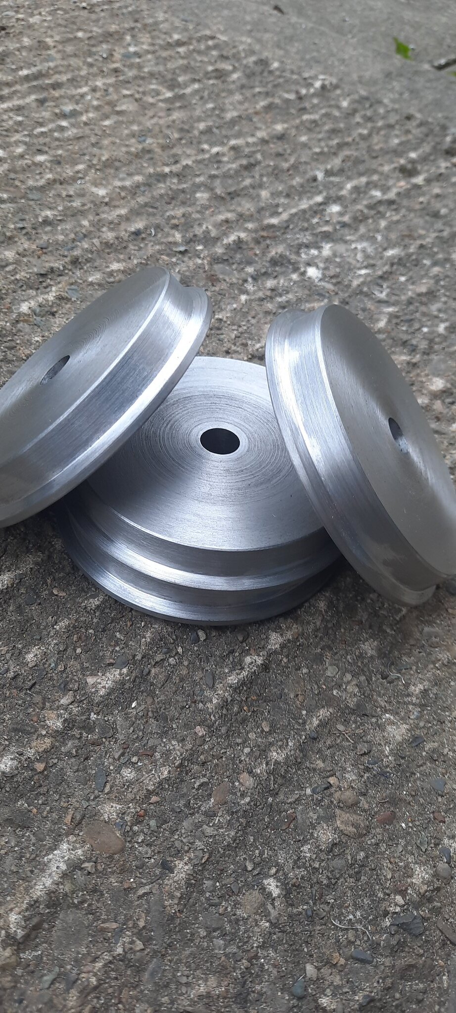 20210925_143502 20210925_143502 by Jon Cameron, on Flickr |
|
|
|
Post by jcsteam on Oct 3, 2021 0:33:51 GMT
Week 2 part 2 After machining the wheels successfully, and feeling pretty eased with them. Me and Vikki my partner talked about Josh running the loco and that he wouldn't wait until the weekend to try it out. An email was sent to my club asking if anyone had some portable track and a riding car which could be borrowed for his birthday, allowing him to have a ride. My request was answered and I set off a couple days later to collect the lengths of track and the riding car.  20210923_202812 20210923_202812 by Jon Cameron, on Flickr Having already asked and been granted permission to give the riding car a clean up, repaint, and recover the seat. I set about dismantling the riding car so I could clean it up throughly. 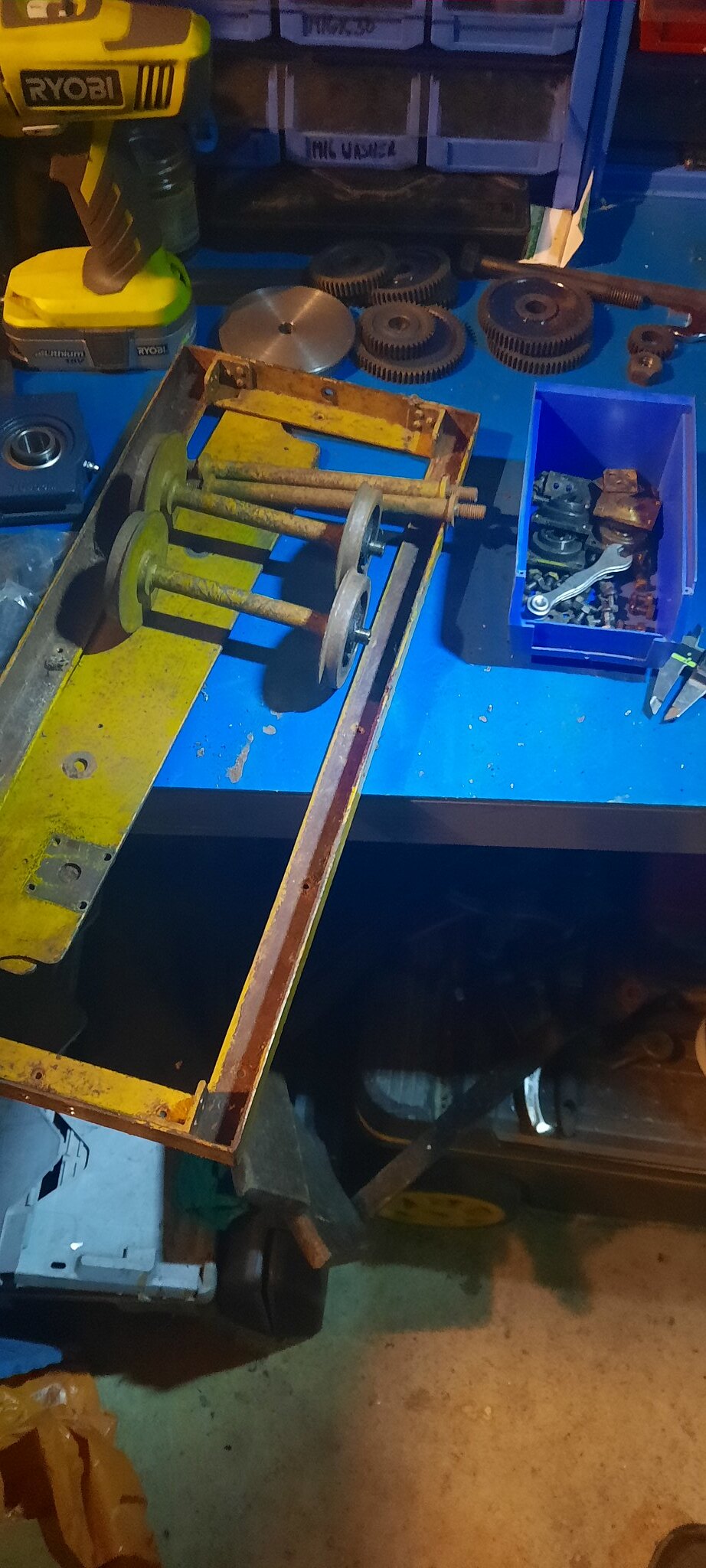 20210925_232155 20210925_232155 by Jon Cameron, on Flickr  20210926_000445 20210926_000445 by Jon Cameron, on Flickr  20210926_095950 20210926_095950 by Jon Cameron, on Flickr Having not got a faceplate to drive the dog so I could clean up the round part between centres I used two dogs instead, and an elastic band, I was only using emery paper, and scotch bright so this worked well for been able to change the parts out quickly.  20210926_104731 20210926_104731 by Jon Cameron, on Flickr Painting began as soon as the parts were cleaned up. 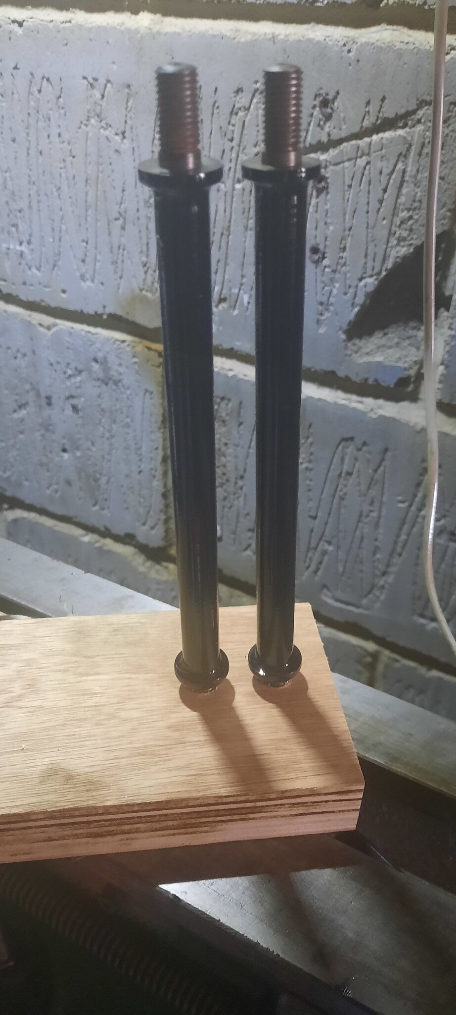 20210926_114426 20210926_114426 by Jon Cameron, on Flickr  20210926_114338 20210926_114338 by Jon Cameron, on Flickr With the framework stripped of paint, the whole riding car chassis was assembled, and then painted as an assembly, the wheels and stretchers that were now dry, giving an idea hand hold to turn the truck around without getting too much paint everywhere. 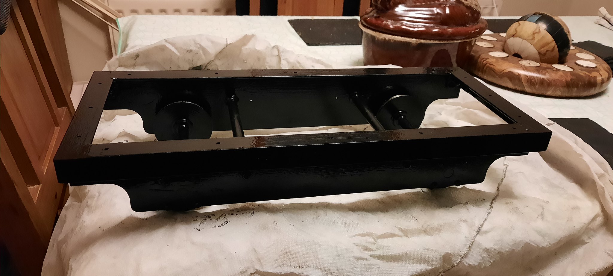 20210928_205717 20210928_205717 by Jon Cameron, on Flickr  20210928_205731 20210928_205731 by Jon Cameron, on Flickr 20210928_205731 by Jon Cameron, on Flickr  20210928_205807 20210928_205807 by Jon Cameron, on Flickr After letting the paint dry a few days, and giving Vikki time to shop for some new foam and grey seat material. I acquired a new piece of 25mm thick plywood that was cut to size. Given a coating of fence preservative, and allowed to dry. Then Vikki made up a new seat pad to be screwed onto the frame.  20210930_104355 20210930_104355 by Jon Cameron, on Flickr  20210930_104653 20210930_104653 by Jon Cameron, on Flickr  20210930_104750 20210930_104750 by Jon Cameron, on Flickr Now my boy would have some track and a riding car to be able to test his train out in the garden. |
|
|
|
Post by steamer5 on Oct 3, 2021 0:42:34 GMT
Hi JC,
You were lucky! Youngest son at about 12 wanted a 5"BIG BOY!! THAT was NEVER going to happen!
About that time there was a construction article for Toby Tram in the Australian Model Engineer mag which he was ok with. Toby now has about 18 years of running under his wheels.
Best advice I can give you is buy the best controller that you can afford, preferably one that has regen braking & spring return to zero power / off. I built Toby so that at max motor revs he would only do just over the max speed used here in NZ, that way your son wont get into trouble speeding!
Your build rate is way faster than mine was! Looking good & following along!
Cheers Kerrin
|
|
|
|
Post by jcsteam on Oct 3, 2021 1:12:21 GMT
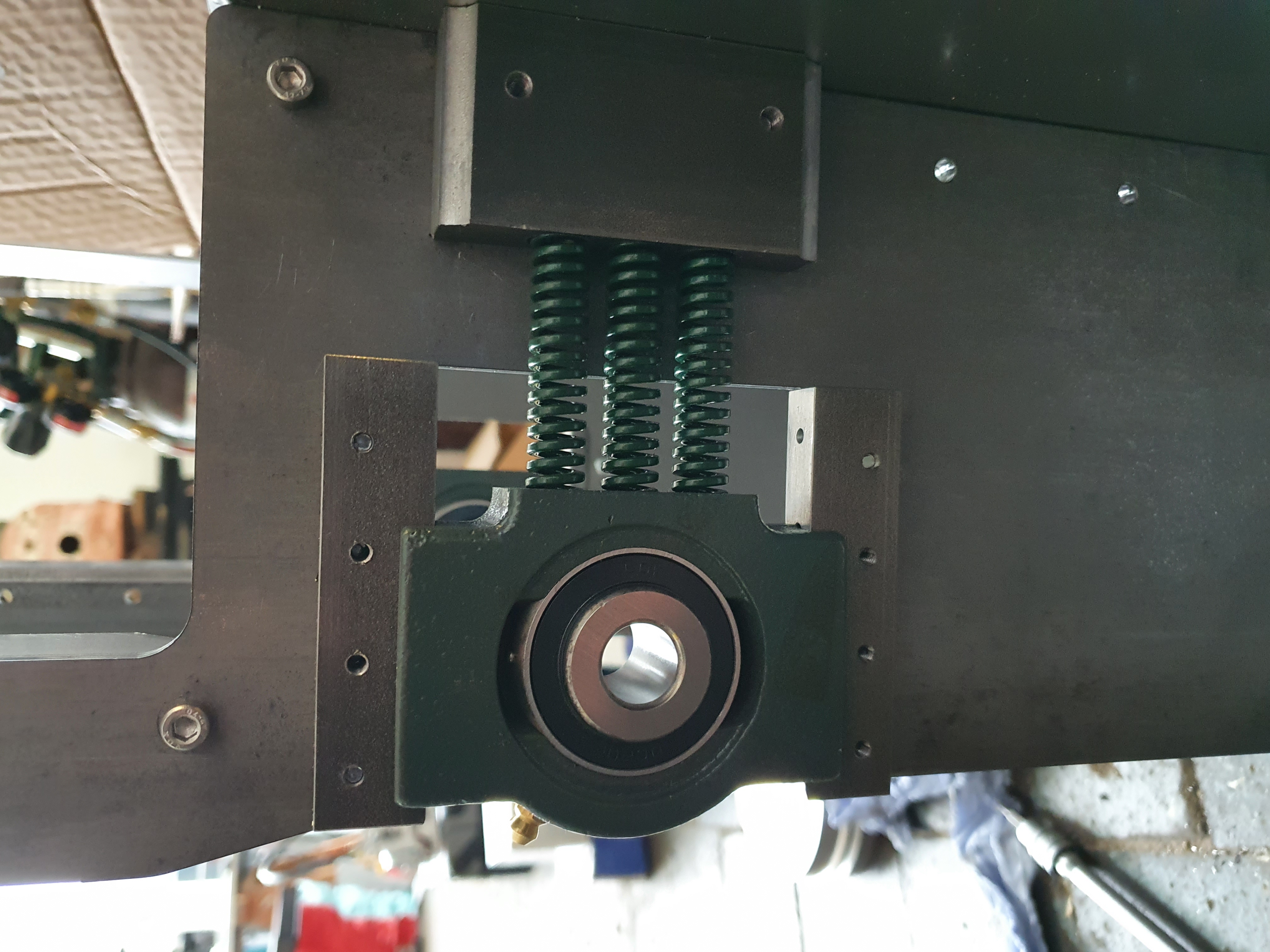
Week 3 So onward with the loco. Buffer angle was squared up on the buffers and the alignment checked for measurements nylock nuts been used as these will never be coming apart again.  20210928_230904 20210928_230904 by Jon Cameron, on Flickr The frames had several small holes chain drilled (badly) across the top of the horn slots, these then were slit either side with a slitting disc in the angle grinder taking care not to go too far over. Using a hammer and a metal chisel these were then broken out. The remaining metal been taken most of the way back again with an angle grinder carefully. The remaining metal was filed away with 2nd cut and fine fines, and also a square and vernier to check alignment for the take up bearings.  20210929_192946 20210929_192946 by Jon Cameron, on Flickr  20210929_194305 20210929_194305 by Jon Cameron, on Flickr  20210930_200718 20210930_200718 by Jon Cameron, on Flickr 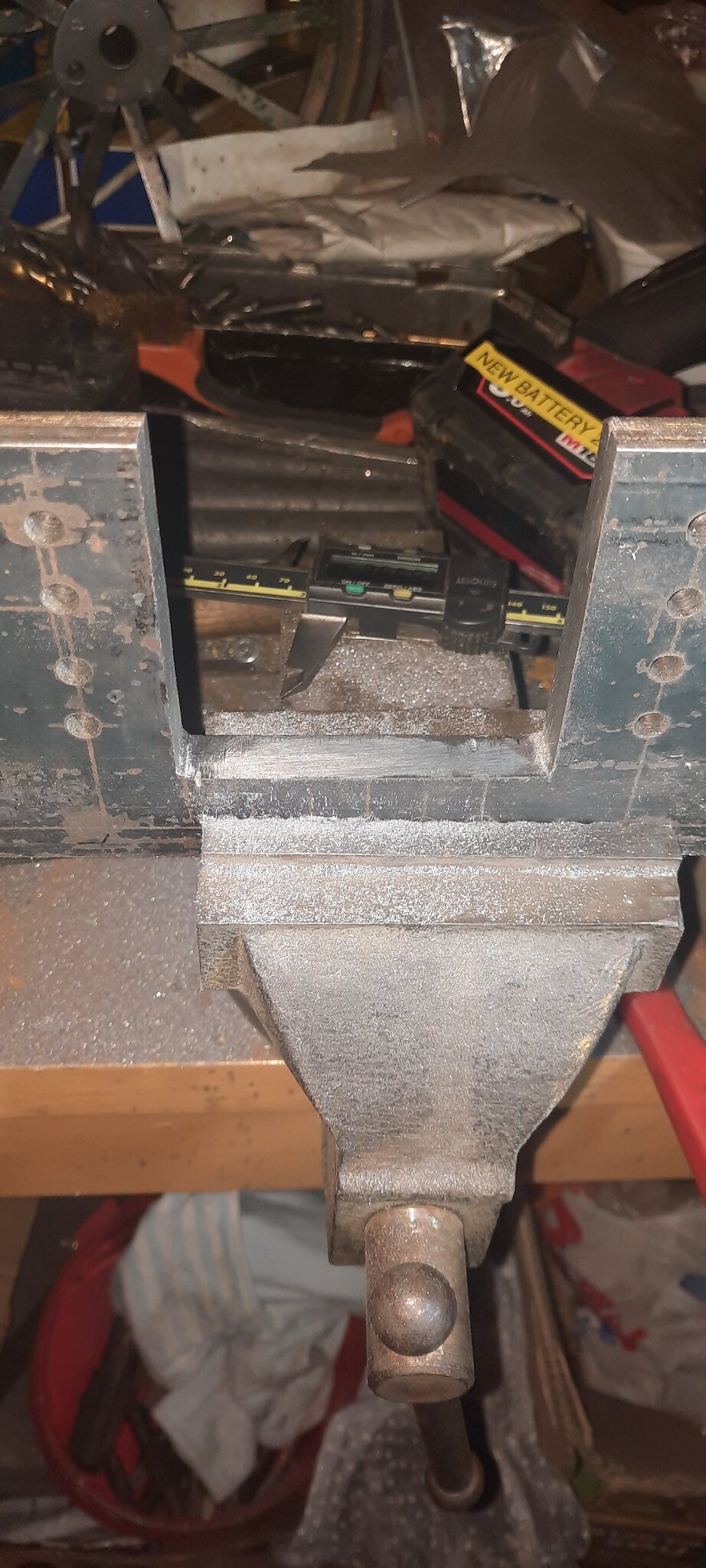 20210930_200711 20210930_200711 by Jon Cameron, on Flickr When the take up bearings arrived that I was to use as axleblocks, I set about chopping the top off them with a hacksaw. The frame only measures 100mm so these would be solid if not removed and thus allows some suspension to be installed.  20210930_124414 20210930_124414 by Jon Cameron, on Flickr  20210930_124431 20210930_124431 by Jon Cameron, on Flickr The slots in the sides of the take up bearings was smaller than I thought. Time to machine the horn strips which are basically the same thickness as the frame. The vertical slide was set up on the cross slide, and an angle plate bolted to that. With a milling cutter in the spindle collet. The strips which had already been machined to width. Were now clamped to the angle plate. With the depth of cut determined the saddle was locked in place. Then the milling cutter was Brough to be just touching the top of the steel. A total of 0.036" was removed from the 8 pieces.which gets them to be a nice fit in the bearings when added to the frame. Unfortunately the milling cutter walked out the myford collet nose due to chatter, so they are not all perfect but they are all usable.  20210930_225341 20210930_225341 by Jon Cameron, on Flickr  20211001_005440 20211001_005440 by Jon Cameron, on Flickr The frames when I was happy with the horn slots and that there were no more holes to be drilled where split apart and all edges and holes were de-burred with a file. The suspension points were the first to be drilled and bolted up. The hornsllts were then each marked in turn 1-4 with centre pops to the inside of the frames. The bearings been marked the same, then each slot filed with a fine file to achieve a good sliding fit. Then once this was all done the strips were added clamped with mole grips, and drilled through using successively larger drills, and using the holes in the frames as a guide. 20211001_005440 by Jon Cameron, on Flickr  20211001_224721 20211001_224721 by Jon Cameron, on Flickr 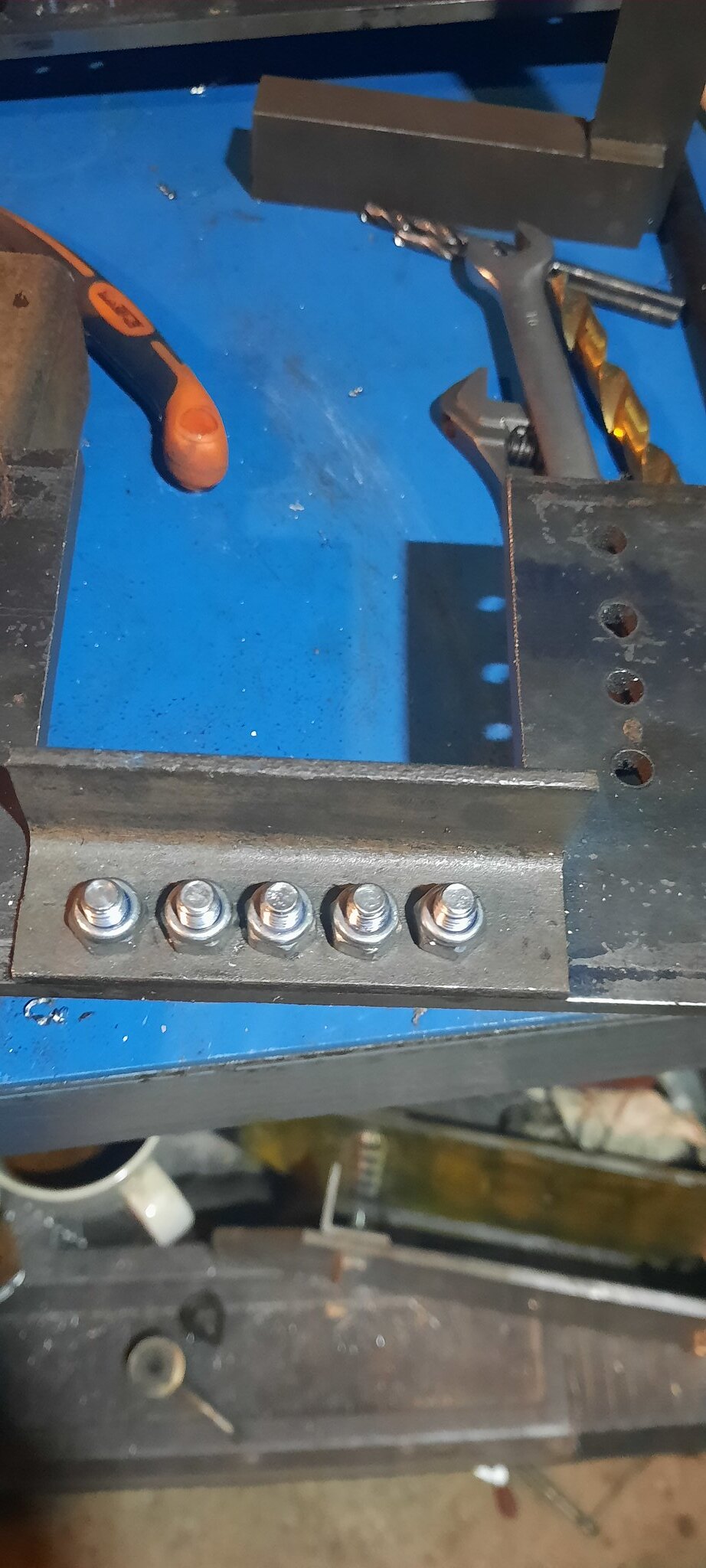 20211001_230843 20211001_230843 by Jon Cameron, on Flickr 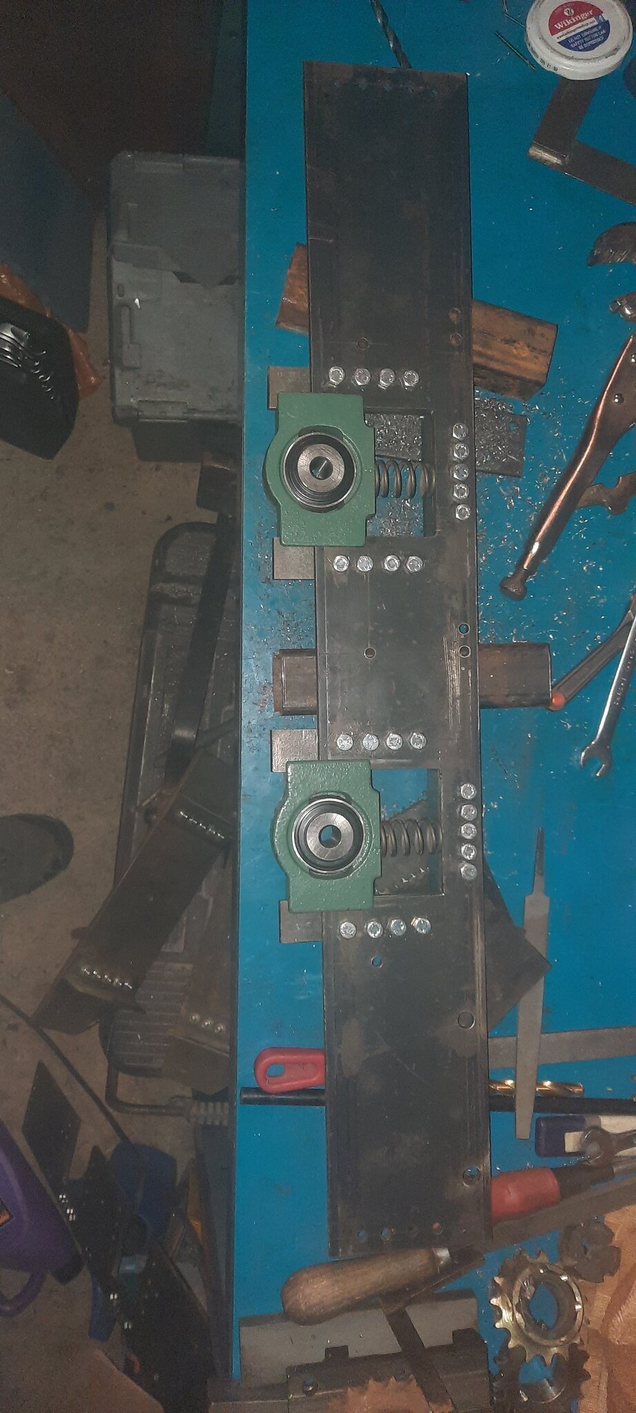 20211002_151026 20211002_151026 by Jon Cameron, on Flickr  20211002_175412 20211002_175412 by Jon Cameron, on Flickr So this brings you all up to date with me and where I've got to, I didn't mention the two days that I was laid up with a real bad cold, knocked me for six and was off work. The frames have been clamped together with axleboxes and springs been placed into position. I need to have a clean up and reset my lathe for turning the stretcher bars between the frames, and the axles next. As well as turning the four eccentric spring retainers. The mounting hole been offset. The retainers for the axleboxes are still to be made and when I looked at the photo I realised I hadn't drilled two holes for the thickening pieces in one side. So it'll be coming apart again and have them drilled. I have run out of hex bolts so need to buy some more. Parts have started now to arrive for the build, a battery, charger, cable, taperlock bushes ect. I was hoping and still am, to have the chassis rolling by the end of the weekend, though may be more likely to be Monday or Tuesday next week. But here is current progress of the loco to spur me on, clamped together and everything in its place.  20211002_181421 20211002_181421 by Jon Cameron, on Flickr |
|
|
|
Post by jcsteam on Oct 3, 2021 1:31:36 GMT
Best advice I can give you is buy the best controller that you can afford, preferably one that has regen braking & spring return to zero power / off. I built Toby so that at max motor revs he would only do just over the max speed used here in NZ, that way your son wont get into trouble speeding! Your build rate is way faster than mine was! Looking good & following along! Hi Kerrin, The controller is a cheap one from ebay, it is not ideal, but then neither is trying to build a fully working loco in 5 weeks. It can however be upgraded in the future. For now a cantilever brake is going to be employed onto a disc for stopping. The gearing has been worked out so that it can't go above 5mph. With its weight, and it weight a fair bit already let alone with two batteries added, it will be be able to pull quite a bit! The build rate isn't by choice, neither was breaking my ML4 which I'm still pretty cut up about. But these things happen. From when I've got in from work around 5:30, until 1,2 sometimes 3am I've spent working on the loco, plus each weekend. We're going away next weekend so I need to be at a point where I'm happy I can complete it. I'm actually going to pick up a loco from Newport for myself. Vikki has booked somewhere to stay so we'll be having a weekend of the trek down to South Wales. Regards Jon |
|
|
|
Post by steamer5 on Oct 3, 2021 4:19:20 GMT
Hi Jon,
Yep I started with a cheep controller...a basic 4QD 12 volt one that a friend converted to 24v for me. It worked great but as I'm always allowing other to drive Toby & the number that said "oh i thought it had regn braking" despite telling them, a couple of years back i upgraded it. Toby weighs in at 35 to 40 kgs...i can only fit 2 x 40 amp marine batteries...another story... happily pulls 2 adults & 1 kid ( trolley is only 1200 long) pretty much all day, motor is from a wheel chair & is only 250w if i remember correctly.
Sounds like you have a fun weekend planned, safe travels...looking forward to photos of the new toy!
Cheers Kerrin
|
|
|
|
Post by d304 on Oct 3, 2021 8:44:12 GMT
Hi Jon
Nothing better than a young engineer with their own loco! When I joined our local club, I thought the first thing I would build would be a loco for my son so he could be included in the fun of driving a loco.
I always liked the look of the old Tri-ang 0-4-0 Hornby “Dock Shunter” and scaled one up to approximately the size you are thinking. Some years ago I picked a book up on Bagnall Locomotives in New Zealand and amongst the excellent book was a story about how the Tri-ang loco was inspired by the Bagnall 0-4-0 “TR” built for the New Zealand Railways in the 1950’s. Tri-ang had to modify the body to accept the motor and my artistic licence was to accept the batteries under he bonnet.
At the time in our club in Australia a lot of the simple battery powered locos used two 70 amp hr batteries in series to provide 24volts through a simple controller, 200 watt motors. The hand control was off an electric scooter and had the benefit of a a internal spring that acted like a deadman’s handle if let go; ideal for children. Ours is chain driven from old bicycle chain and gears and sprockets. I kept the two batteries down as low as possible to keep the centre of gravity as low as possible and the body was made out of sheet metal, bent and rolled. Initially I built a small 4 wheel wagon to ride then two American style flat cars that could be used on both raised track and ground level with either a model shipping container or later a foldable boat seat. As Kerrin said, each carriage was about 1200mm long was ideal. This size fitted into the boot of the smaller car we had at the time.
The loco runs for the whole day and I think of the fun our son had as we visited clubs around New South Wales. I can only think once when we had a problem, taking it off the track only to find it was filthy steam locos oiling the track that caused our lack of traction!
The kids will have fun with it! Mother’s might fret as the apparent speed they can appear to travel. Our son son has moved on to beer and girls and hasn’t been down to our track in ages, saying he is waiting for the current workshop steam loco to be finished.
Send me an email and I will send images of “Docky”.
Regards
David
|
|
|
|
Post by jcsteam on Oct 3, 2021 9:50:22 GMT
Hi I've sent you a message with my email address.
The controller can and likely will be updated in the future. A dead man's switch isn't something I've worked into the design though. Can a push switch be wired into one of the terminals of the potentiometer, so when it's released the power is cut, or do they not work like that. I don't like the idea of having the motor power, wired to a push button on the handset. Too much current.
Regards
Jon
|
|
lesstoneuk
Part of the e-furniture
 Retired Omnibus navigation & velocity adjustment technician
Posts: 373
|
Post by lesstoneuk on Oct 3, 2021 11:45:02 GMT
Hi I've sent you a message with my email address. The controller can and likely will be updated in the future. A dead man's switch isn't something I've worked into the design though. Can a push switch be wired into one of the terminals of the potentiometer, so when it's released the power is cut, or do they not work like that. I don't like the idea of having the motor power, wired to a push button on the handset. Too much current. Regards Jon The simplest dead man's is a jack plug and socket on a length of cord. Wire the plug to loop from +ve to -ve and put this in the main control loop. Plug comes out due to loss of driver or driver away, all circuits are dead. |
|
|
|
Post by flyingfox on Oct 3, 2021 14:00:44 GMT
Greetings, well done Jon, for taking on the challenge, and i wish you success in your endeavours. Re the 4QD cobtroller, although they are low cost, these controllers robust, and well constructed. I am sure that the hand set which they also sell has a "dead man" function, in that the driver needs to keep the progressive throttle lever pressed on all the time, when released, it springs back and full regen braking is applied.
have a look at their website.
regards
Brian B
|
|
|
|
Post by theflyingscotsman on Oct 3, 2021 17:25:17 GMT
This is brilliant, and I love that your lad is into railways a bit. Top dad points for that challenge
|
|
|
|
Post by jcsteam on Oct 3, 2021 18:36:55 GMT
Greetings, well done Jon, for taking on the challenge, and i wish you success in your endeavours. Re the 4QD cobtroller, although they are low cost, these controllers robust, and well constructed. I am sure that the hand set which they also sell has a "dead man" function, in that the driver needs to keep the progressive throttle lever pressed on all the time, when released, it springs back and full regen braking is applied. have a look at their website. regards Brian B Thanks Brian, perhaps I should have said what the budget of this loco is from the start. I have 5 kids between me and Vikki, eldest is 13, youngest soon to be 6. We don't usually spend more than a couple hundred on the kids birthdays. £2000 for a ready built option was a no go. So instead the budget was set at £200, so far I'm within that budget. But expect to go over it with silly bits like cables. But everything is now bought and I think worked out. I just need to try get more time on it to build it. I've still not turned the axles, but have just made a plate for my fixed steady from the ML4 to be used on the ML7. So I'll be turning them and the stretchers tonight if time allows. The 4QD controller alone would have blown the budget, and remember this isn't going to be a loco that endures lots of public running, pulling loaded coaches, but a loco that trundles around a bit, for my lad to enjoy. It can be upgraded in the future, as can any of it. For now I'm focused on just getting the wheels turning forwards and backwards. |
|
|
|
Post by jcsteam on Oct 3, 2021 18:43:25 GMT
Today I've not had much time to do anything other than setup for machining the stretchers.
I did pay our local hardware shop a visit today though, not a B&Q for once but a proper merchant corner shop affair. Needless to say that I've ordered some 9mm ply from him precut to the correct size for the body, so now I just need to collect and pay for it.which hopefully will be tomorrow. Vikki is getting the job of gluing the body together and sanding it down ready for paint.but I have to drill and cut some holes out for the windows. A friend from work has some perforated sheet metal mesh. Which I'll be having a little piece of, and he's also getting me a small piece of perspex for the windows. Still a long climb to get it done.
Regards
Jon
|
|
|
|
Post by jcsteam on Oct 5, 2021 2:22:39 GMT
Well my little boy decided to draw a picture of his train around the house.  20211003_201925 20211003_201925 by Jon Cameron, on Flickr If that's not motivation I don't know what is. Sunday night saw a big fail on my part, while making the stretcher bars for the frames. As I was tapping the hole I broke my only M6 tap. Gutted was an understatement, and I went to bed at 1am quite miffed. I'd also broken one of my slowcomb drill bit ends, so was definitely bedtime. Start again the following evening with a fresh head.  20211003_215712 20211003_215712 by Jon Cameron, on Flickr  20211003_221104 20211003_221104 by Jon Cameron, on Flickr  20211004_000906 20211004_000906 by Jon Cameron, on Flickr So come Monday, go into work as normal, on my brain all day where I'm going to get a tap for that night to progress the frames. I work in a maintenance department, and thankfully after asking a few of my colleagues. I ended up coming away with x3 M6 taps......result. So get home from work and dive straight into work on the loco. Three stretcher bars, turned exactly the same dimensions, and all tapped M6 without any drama. Started in the lathe and finished in the vice. I don't have a backstop for this lathe yet, so I improvised using a 4mm Allen key and the stock pushed up against it. When the jaws were tightened this was removed with the parts reversed in the chuck I now could face them all exactly the same. 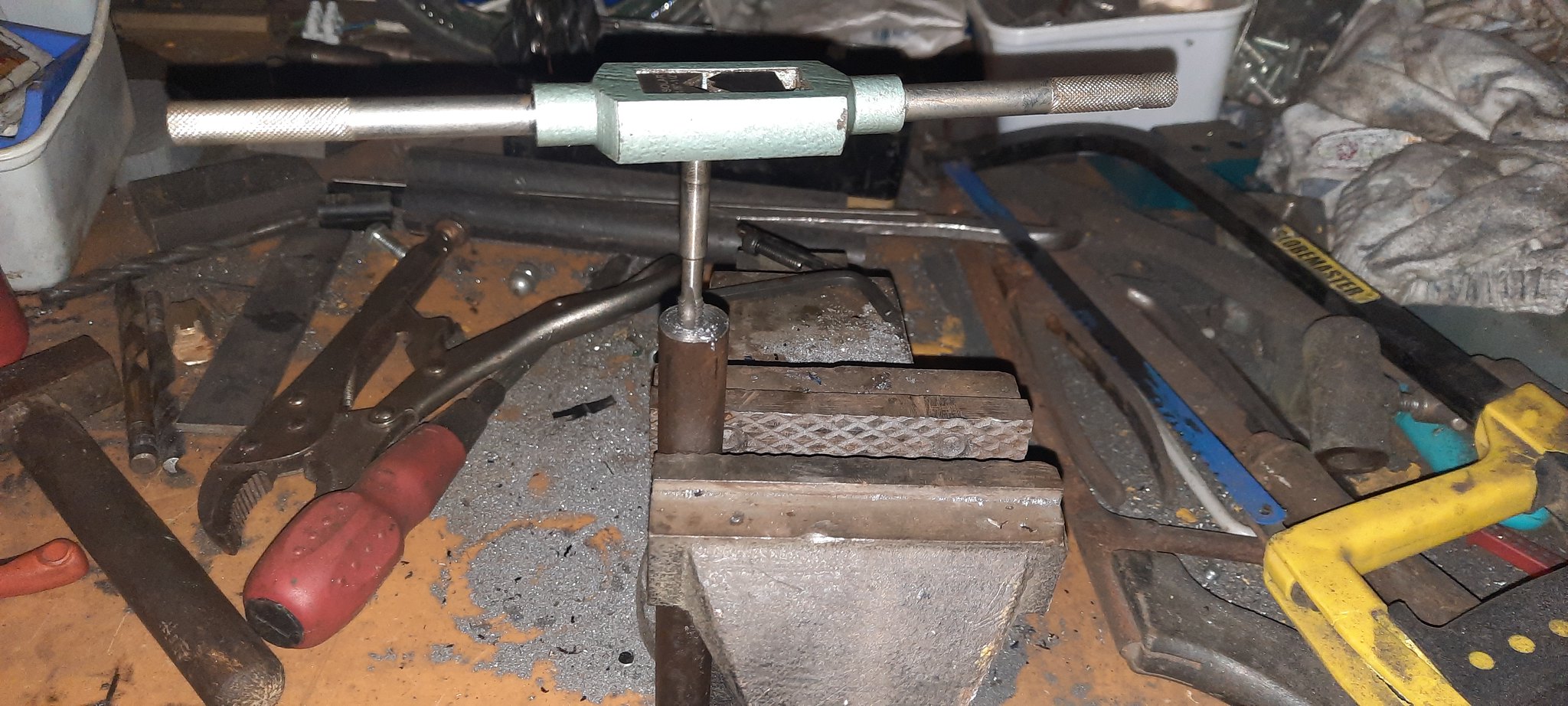 20211004_191943 20211004_191943 by Jon Cameron, on Flickr  20211004_192120 20211004_192120 by Jon Cameron, on Flickr  20211004_192812 20211004_192812 by Jon Cameron, on Flickr It had occurred to me earlier in the day that I had no means to fix the footplate to the chassis. So I cut some strips of angle to be bolted up. I made some holes in the buffers to attach the angle. They were then clamped in place and the holes drilled through from the other side. Then bolted to position with hex bolts and nylock nuts.  20211004_201548 20211004_201548 by Jon Cameron, on Flickr  20211004_201557 20211004_201557 by Jon Cameron, on Flickr  20211004_213931 20211004_213931 by Jon Cameron, on Flickr 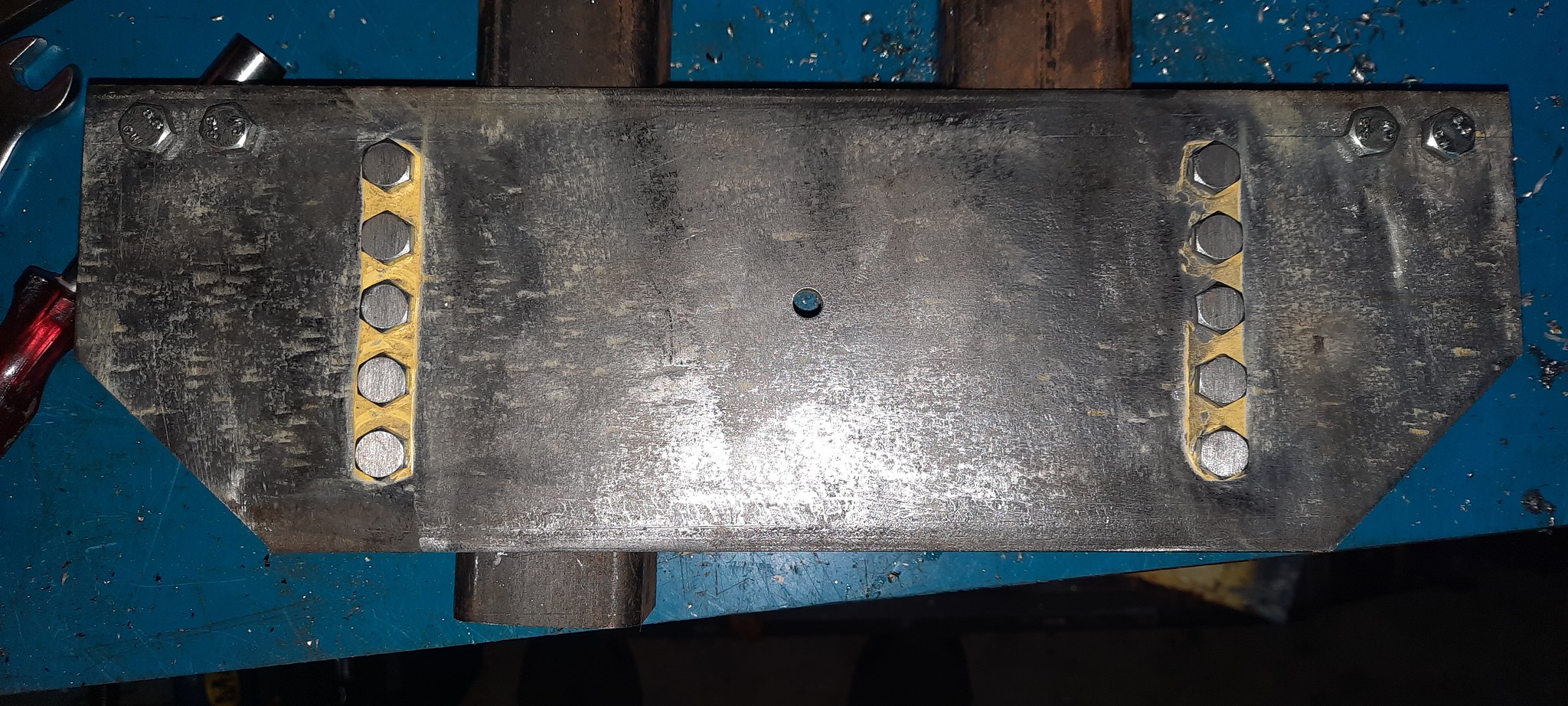 20211004_213945 20211004_213945 by Jon Cameron, on Flickr  20211004_213957 20211004_213957 by Jon Cameron, on Flickr 20211004_213957 by Jon Cameron, on Flickr So happy that I could attach everything to the frames I began to assemble them. First the stretcher bars were loosely tightened up, but not too tight that they couldn't move slightly. The buffers were put on each end, and the ends clamped up enough to hold them. Then began some carful measuring diagonally to ensure the ends of the frames which had previous been milled on the bridgport at work were the exact distance from each other corner to corner. The tops of the buffers and the tops of the frames both milled edges were tapped lightly inline with a hammer. Then all was double checked and checked again. Before the stretcher bars were fully tightened, and then began the series of drilling through for the buffer angle. All 20 holes were drilled with four drills, 1st: with the same sized drill as the hole to get an accurate centre. 2nd: with a pilot drill, 3rd and 4th with stepped drills upto the full 6mm hole. Then bolted up. I started with one in each corner to set the buffers in place then removed the clamps and did the rest.  20211004_231525 20211004_231525 by Jon Cameron, on Flickr I made up the countershaft and attached the taper sprocket to that. This hasn't been bolted up yet as it has to come out again.  20211005_022325 20211005_022325 by Jon Cameron, on Flickr So that's where I'm at for today. Electronics have all turned up, which has showed up an error on my part. As there isn't enough room for the motor to fit above the countershaft and engage with the 20DP gears. I will have to use a larger sprocket which mucks up my gearing and means the loco will be faster than I wanted. I'd calculated for 5mph. This may get swapped out in the future for chain and sprockets, to reduce the speed. Lastly for tonight/this morning (yawn!!!) I picked up the Plywood today to make the body, panels all precut to size. So my partner Vikki has the job tomorrow of sanding them all down ready to mark up and cut the windows and front grill out.  20211004_131952 20211004_131952 by Jon Cameron, on Flickr Jon |
|
|
|
Post by suctionhose on Oct 5, 2021 5:18:14 GMT
I did something like that for my 5 yr old (Toby the tram). Huge success! He drove it everyday on the home track for 60 days straight! I had this battery charging line going 24/7 in the garage...
He'll get a lot out of it I promise!
|
|
|
|
Post by ettingtonliam on Oct 5, 2021 6:45:31 GMT
I'm amazed at the speed you work! Faced with this problem I'd have probably said something like 'But Father Christmas is bringing you one for Christmas, the elves are already making it, we'll get you xxxxx for your birthday', and so buy more time. I suppose that would be lying to the child, and not setting a good example though.
|
|
|
|
Post by jcsteam on Oct 5, 2021 14:42:34 GMT
Hi, Liam?
The problem I have is he hasn't asked for anything else for his birthday. He's only asked for a ride on train. The pressure is on so sleep deprivation is the order of the day. Essentially I did 9hours on the loco last night. But things were going well and been behind, I took the opportunity to catch up and get the frames built! They should not need to come apart now.
Regards
Jon
|
|
|
|
Post by jcsteam on Oct 6, 2021 0:54:41 GMT
Hello all, Not a lot done tonight as only a three hours. Footplate cut out, used a piece of 25mm angle as a striaght edge, with some 4mm flat, to pack it from the edges of the buffers to draw a striaght line with a marker pen. This was then cut out with the angle grinder, cleaned up with a file to straighten and remove cut marks, finishing with a fine file, and deburing the edges.  20211005_192210 20211005_192210 by Jon Cameron, on Flickr WD40 sprayed on the underside and cleaned up with scotchbrite pad.  20211005_224103 20211005_224103 by Jon Cameron, on Flickr The footplate was then flipped over (top side facing up) and the frame was then placed on top straightened up, and the angle to attach from the buffers, and frames was marked on the footplate. Also the countershaft was marked on the footplate as this will need to be removed to allow for clearance for the gears/countershaft.  20211005_223947 20211005_223947 by Jon Cameron, on Flickr All holes were drilled by hand using the black outlines as reference. The holes all been countersunk into the top of the footplate, although I need longer M4 countersinks as they don't engage with the nylock nut fully. Plywood bodywork, balanced in place, the double thickness will be routered when glued together to give a radius to the bonnet and cab roof. Front of bonnet will be cut out to allow fitment of some mesh and 30mm pine will be glued on to the front to make it look as a radiator should. Bonnet fixing screw will be a radiator cap turned from brass, angle on the footplate locating and aligning the lower of the bonnet.  20211006_002516 20211006_002516 by Jon Cameron, on Flickr 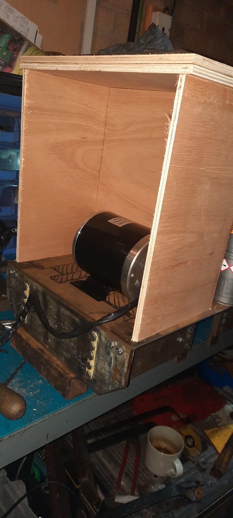 20211006_002613 20211006_002613 by Jon Cameron, on Flickr Lots of gluing and sanding and painting await me. It may not have brakes worked out yet, but it does have a horn 😂😂😂  20211006_005605 20211006_005605 by Jon Cameron, on Flickr Jon |
|
|
|
Post by andyhigham on Oct 6, 2021 9:14:02 GMT
|
|