cfmrc
Seasoned Member

Posts: 107
|
Post by cfmrc on Nov 9, 2022 15:27:29 GMT
That’s very kind of you to say. I am just aiming to continue the very high standard set be Ian Jaycroft. It’s a very fine engine. I think the photos are really teaching grandmother(s) to suck eggs on this forum, but maybe there are some techniques I use that are a bit out of the ordinary.
Tim
|
|
cfmrc
Seasoned Member
Posts: 107
|
Post by cfmrc on Nov 14, 2022 11:35:50 GMT
I have had a busy few days working on the back head for Sir Sagramore. I decided to use 16BA bolts to secure the quarter round-bezel to the cleading rather than soldering: much more controllable. The firebox door assembly was also bolted on. The restraining bracket for the door arm will probably be beefed up a bit - I don’t think it will otherwise survive my poor aim when firing… 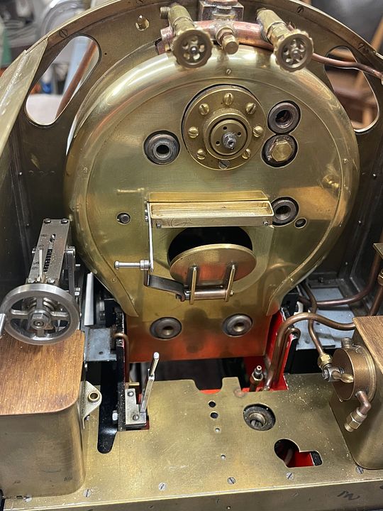 . The cleading was fixed to the back head with a couple of short 10BA bolts into some stays. This then allowed for the pressure gauge and LH injector steam valve spindle mounting to be attached using 14BA slotted screws (I might change these to hex bolts). 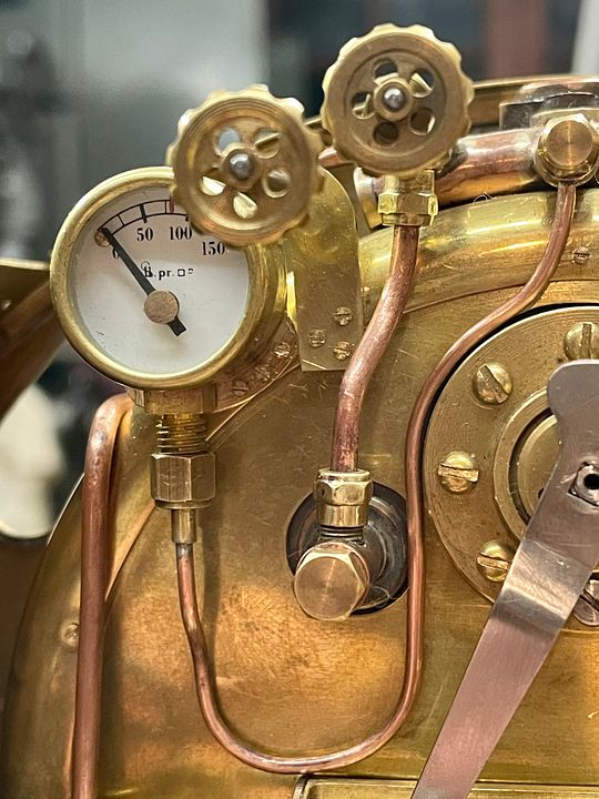 The routing of all the pipes is a real snake’s wedding. 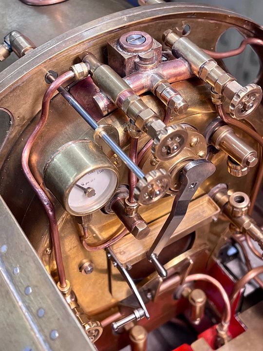 Other than a few small jobs, it just needs the RH injector valve spindle support making and some restraining collars on the shafts to more or less complete the top end fittings. Tim |
|
mbrown
Elder Statesman

Posts: 1,719
|
Post by mbrown on Nov 14, 2022 11:55:46 GMT
Great work!
I am just looking at your top water gauge fitting and wondering how you fit/change the glass?
Best wishes
Malcolm
|
|
cfmrc
Seasoned Member
Posts: 107
|
Post by cfmrc on Nov 14, 2022 13:21:38 GMT
The glass feeds up from the bottom, Malcolm. That is where the access / blanking plug is located.
Tim
|
|
cfmrc
Seasoned Member
Posts: 107
|
Post by cfmrc on Nov 15, 2022 23:31:25 GMT
Sorry to be a bit of a broken record but the cab of Sir Sagramore has now got to a stage where the top end is virtually complete (and I need a break from plumbing). Just need to tighten up a few screws and move on to a larger scale interlude this weekend. 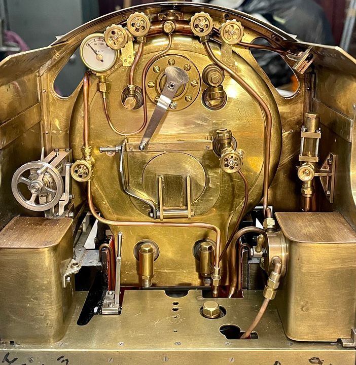 Replacing the front section of the cab improves the appearance considerably. 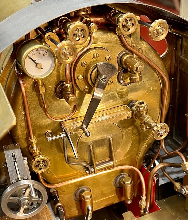 Tim |
|
cfmrc
Seasoned Member
Posts: 107
|
Post by cfmrc on Apr 1, 2023 8:42:27 GMT
Back to the big stuff after working on this:  The original water control for the RH injector on Sir Sagramore was fiddly and deep inside the cab and not at all practical. With the new injector’s streamlined plumbing I thought a water valve towards the back of the tender would be more practical. A commercial valve has therefore been adapted to fit the water pipe below the tender tank. The handle was made and located with a taper pin so that it can be removed for photos. Once it is chemically blacked I don’t think it will be too conspicuous. 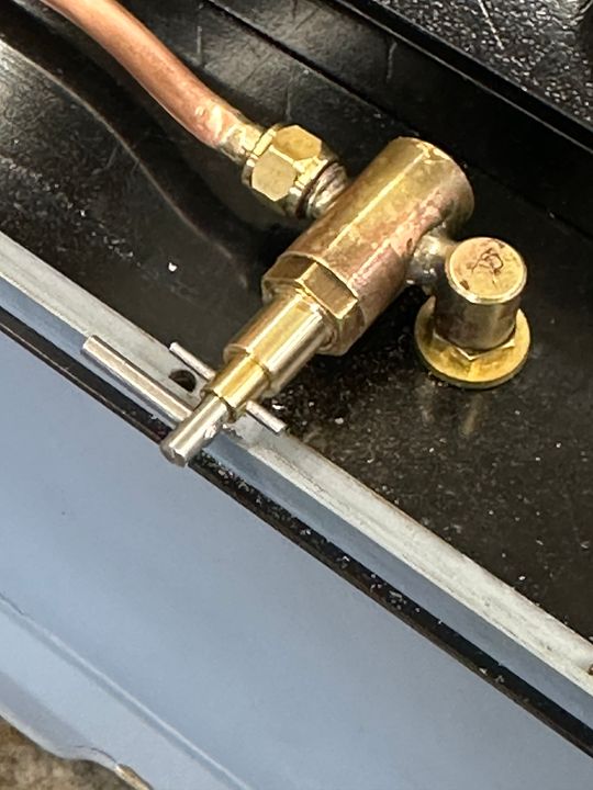 Fortuitously, the taper pin rotates against a positive stop cut into the inside of the valence - which makes positioning it much easier for ‘off’.  The vast majority of the excellent work on Sir Sagramore was made by the late Ian Jaycocks: I am just finishing the job. However, the tender brake wheel should have six curved spokes rather than four. 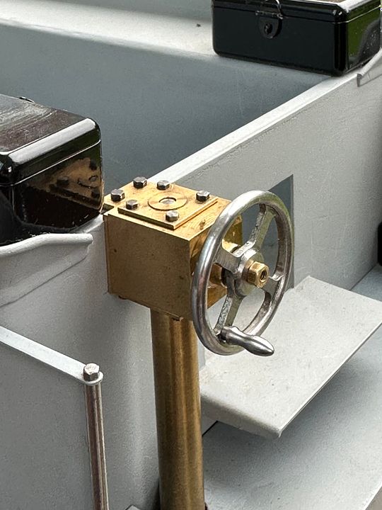 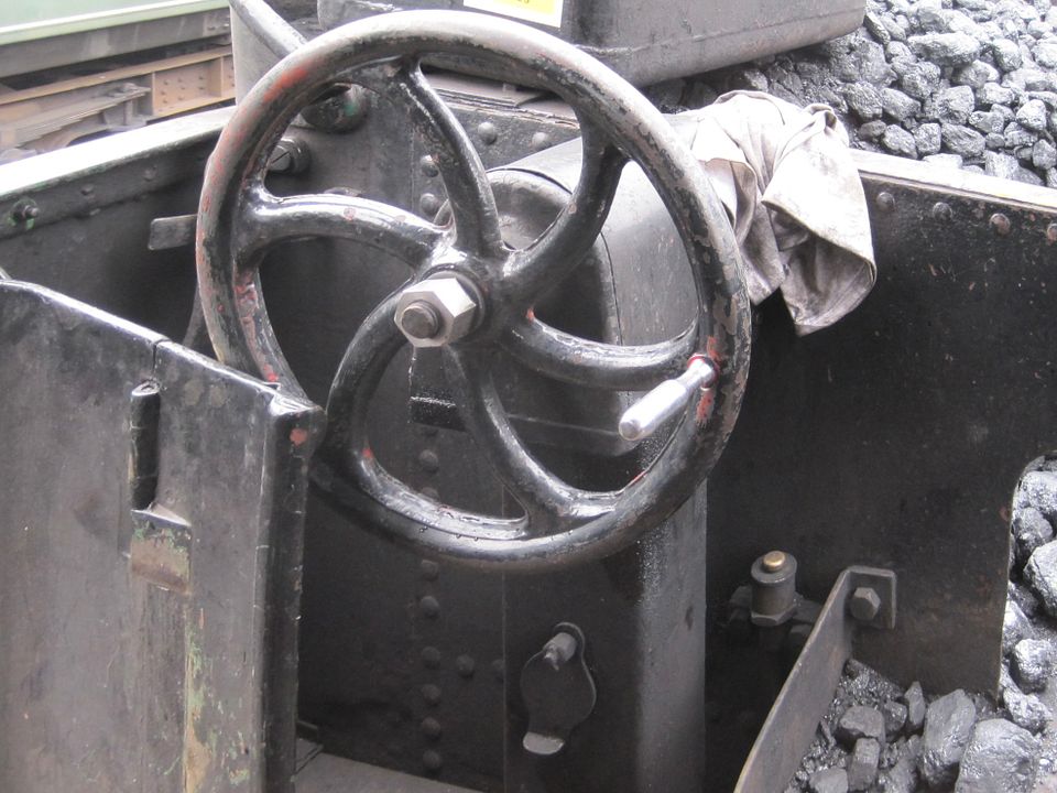 Therefore, a steel disc was turned up and corner holes drilled on a rotary table. A styrene spoke template can also be seen resting in the wheel face. 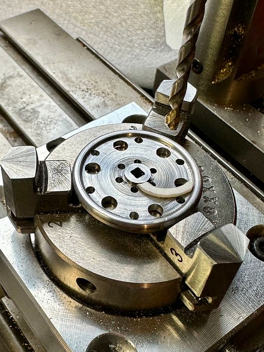 This plastic template was used to mark out the spokes using a gramophone needle. 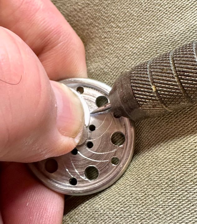 The material between the spokes was fretted out within 40 minutes.and then cleaned up with files 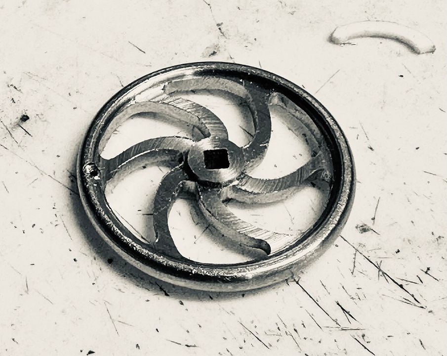 The final finishing, e.g. rounding the spokes used steel burs, stones and a rotary steel brush. The handle spins, for comfort in use… 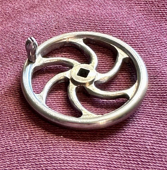 Here it is In-situ. Awaiting a steel 10BA nut.  Ian Jaycroft’s gear drive to the brakes is beautifully engineered, with two quite large bevel gears. It could be made smaller with a gear set from a contra-angle dental hand-piece: but there are other more pressing things to be getting on with…However, I’ll take a look in the workshop at work when the Easter holidays are over as it does rather niggle. I think the next job will be to look at getting castings made for the tender bogie frame stretchers. Tim |
|
cfmrc
Seasoned Member
Posts: 107
|
Post by cfmrc on Apr 4, 2023 13:37:05 GMT
The revised brake wheel drive modifications came early for Sir Sagramore as I remembered that there was an old dental hand piece in the big workshop. After a bit of dismemberment it looked very promising: 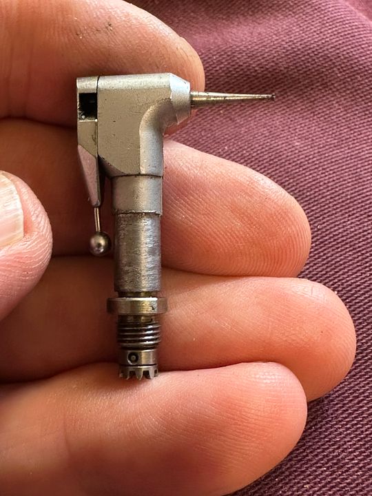 The original brake column was modified to take the hand piece head. 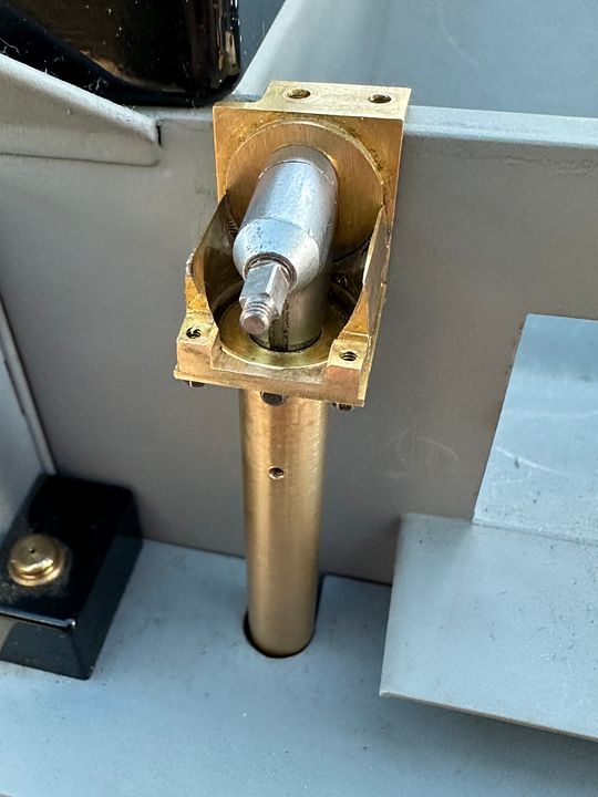 The vertical brake shaft needed splicing onto the hand piece drive, (not a trivial exercise) and the brake handle shaft re-engineered to mimic a dental bur, with a ‘latch grip’ drive. The original box, made by Ian Jaycroft, was significantly re-modelled to be closer to prototype. 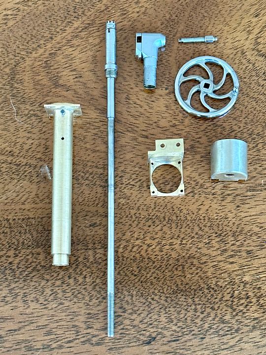 The mechanism works well, as the original alignment of the contrate gears is maintained. youtube.com/shorts/SsE1amzHMXQ?feature=shareThe prototype has a rounded top to the brake column and this now correct on the model. The video probably shows the quite complex arrangements better than photos. youtube.com/shorts/4rAIuoZVZ9Y?feature=shareThe whole assembly is held together with 10 bolts. 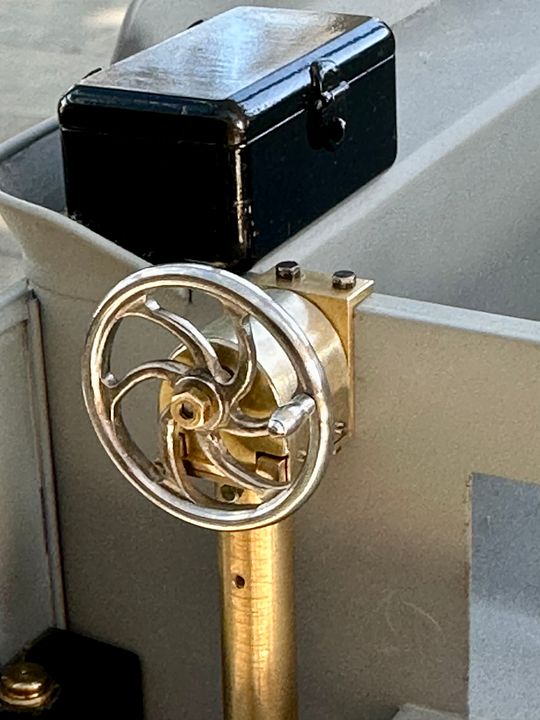 The support column should be square / rectangular in section, so that can be modified quite easily with some brass channel section. The improvement in the view from the tender I think makes all the work worthwhile. 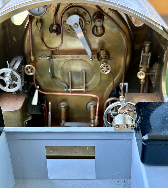 Tim |
|
|
|
Post by steamer5 on Apr 4, 2023 21:55:44 GMT
Hi Tim,
That looks great! Nice bit of lateral thinking to use the dental drill, wonder how many dentist still have one of those in a back room, that could be liberated for a new life!
Cheers Kerrin
|
|
cfmrc
Seasoned Member
Posts: 107
|
Post by cfmrc on Apr 4, 2023 22:10:56 GMT
Actually, Kerrin, virtually all dentists will still use this type of hand piece, from time to time, but a more modern version. Hygienists, most definitely. The gears have a ‘sweet spot’, otherwise can be a bit grumbly.
Tim
|
|
|
|
Post by davewoo on Apr 5, 2023 6:49:28 GMT
lovely work Tim a pleasure to see, glad you're working on the loco again always enjoyed this thread. I like the little sight feed lubricator glass, I seem to have a thing about them and this has inspired me to have a go at a more compact version. Following your progress with great interest.
Dave
|
|
cfmrc
Seasoned Member
Posts: 107
|
Post by cfmrc on Apr 5, 2023 7:53:19 GMT
|
|
JonL
Elder Statesman
WWSME (Wiltshire)
Posts: 2,907
|
Post by JonL on Apr 5, 2023 18:06:41 GMT
I've just spent some considerable time catching up with this thread, I have no idea how I have missed it before. Amazing work.
|
|
cfmrc
Seasoned Member
Posts: 107
|
Post by cfmrc on Jan 14, 2024 7:49:31 GMT
I have resumed work on Sir Sagramore after an hiatus over last summer, re-tubing this (courtesy Guy Hawkins: Rushmore Engineering)  And then re-guilding/ painting 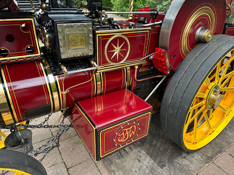 As well as this Pembleton as a distraction 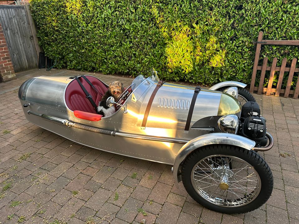 Followed by making a 2mm scale York Road tube station for Copenhagen Fields.  And so I returned to working on Sir Sagramore, just after Christmas. Regrettably the engine had a mishap which required a repair / re-make of the cab side sheets. 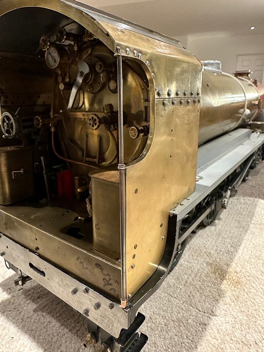 They are now better than they were, but a lesson learnt the hard way! The next job was to work out how Ian Jaycocks intended to assemble the ash pan. As usual, this is a very elegant construction, 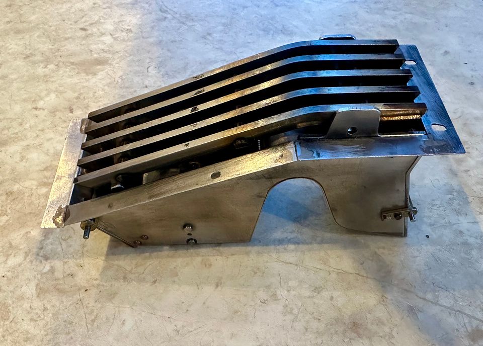 It comprises of three flaps, two dampers and a bottom access / emptying flap, shown here attached to the firebox / boiler.  It took me quite a while to work out how the smokebox was removed in order to get the boiler & ashpan in place on the frames. 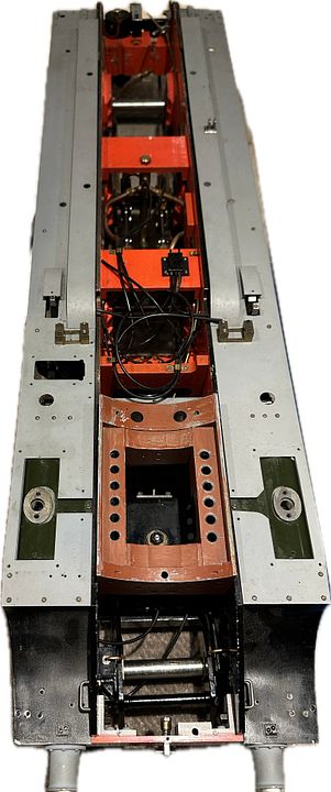 As on the prototype, the ashpan surrounds the rear axle.  Ian had made the linkage for the bottom flap, but I couldn’t work out how he intended to connect it to the back of the engine. The plumbing needed a bit if re-routing. 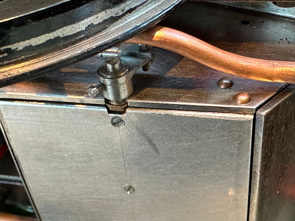 I then noticed that the rear brake hanger stanchion was nearby. He had very cleverly made a nut-bolt consisting of a blind-ended nut with an extension studding to take the second crank, which was held in place with another blind-ended nut. 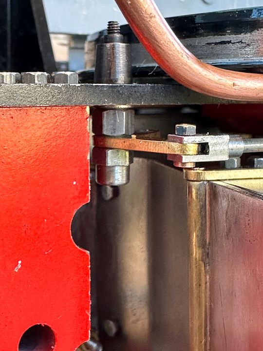 This YouTube video shows the mechanism at work. youtu.be/HzTyvpRoqcQ?feature=sharedIt should be pretty efficient at emptying the front ashpan, especially with the damper wide open. Feeding the grate up into the firebox will need a special tool methinks. My current project is to make the linkages for the front and rear dampers. The controls will probably be mounted on the back head cleading. Apologies for the delay and such a long post, but I have far many projects to keep me occupied. Tim |
|
cfmrc
Seasoned Member
Posts: 107
|
Post by cfmrc on Jan 15, 2024 11:21:20 GMT
I realise that there is some discussion on blower hole sizes elsewhere in this section, but what is the consensus on this elegantly engineered arrangement for Sir Sagramore? 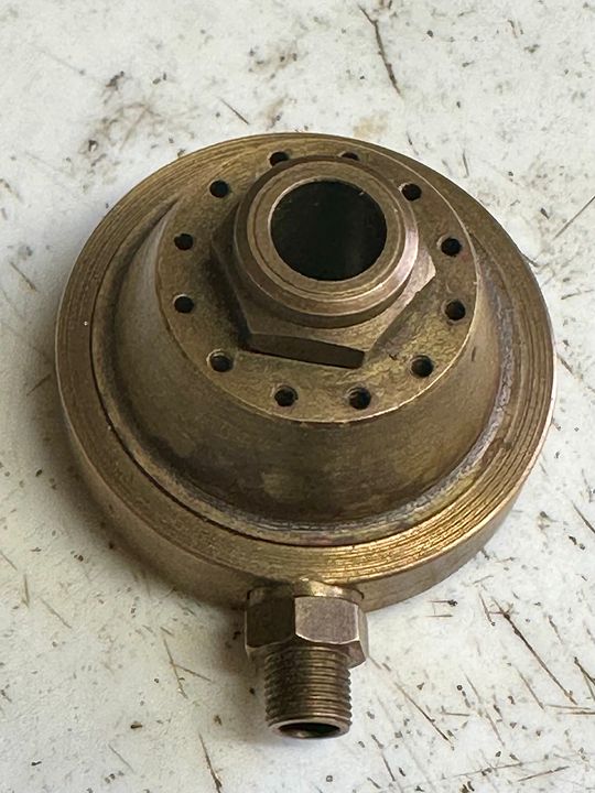 The holes are 1mm diameter and angled to follow the external shape. The blast pipe petticoat is well shaped to capture the jets. Seems a bit excessive; the supply plumbing is not very large. Tim |
|
uuu
Elder Statesman
your message here...
Posts: 2,808
|
Post by uuu on Jan 15, 2024 12:23:06 GMT
I agree it looks excessive. If you could make bungs for the holes, you could experiment with their number. Or a slotted disc, retained by the blast nozzle.
Three or four open holes would be my guess for a reasonable result.
Wilf
|
|
cfmrc
Seasoned Member
Posts: 107
|
Post by cfmrc on Jan 24, 2024 22:17:29 GMT
After an inordinate amount of thinking and puzzling I have now made the front and rear damper linkages for Sir Sagramore. 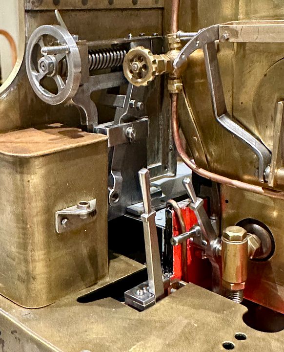 The rear linkage is simply a rod that links to the damper clevis and snuggles in close to the back head. 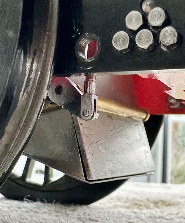 The rod is located by a grooved bobbin that centralises it with low friction. The top is rebated and has a separate top hat 12BA bolt assembly. 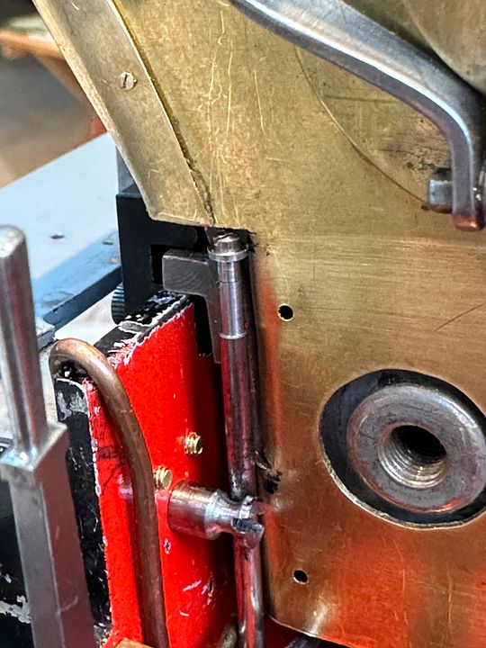 This rod has a rotating handle that locks it open by resting on the frames (a detent will be filed in when the boiler is next removed). To rest the concept, a lump of styrene was carved to shape. 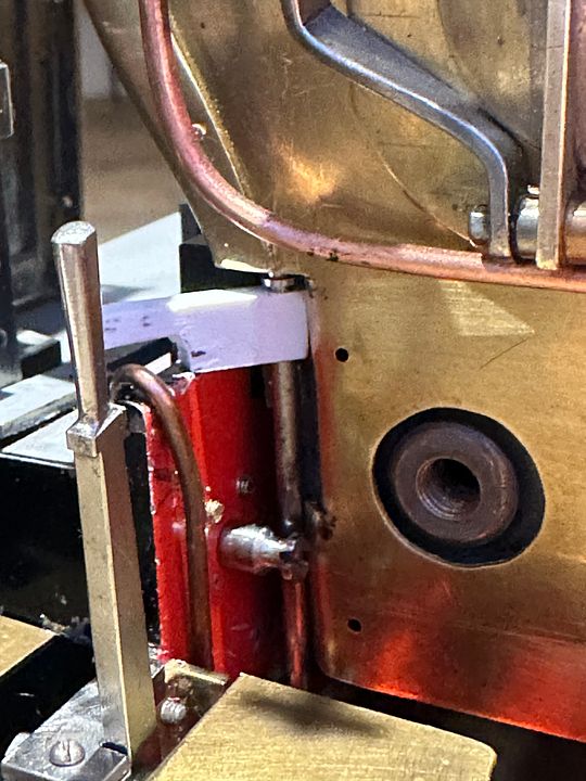 This was then converted to metal and can be seen here with the handle in closed position. It will be prevented from moving medially by the support component of the front damper. 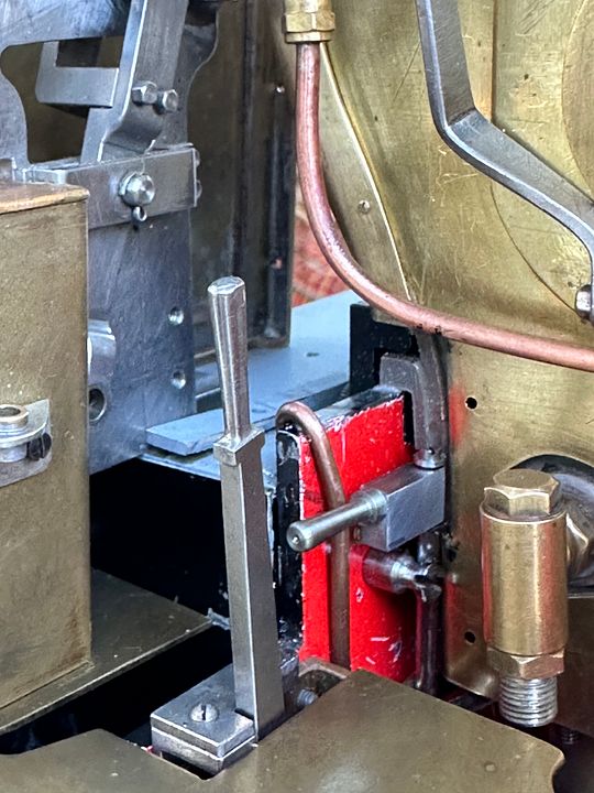 The pillar that supports the front damper lever has a rebate to locate the rear damper body when in the closed position.  In this image, the dampers and drain cocks are in the open position; the brass nut will be replaced with steel. 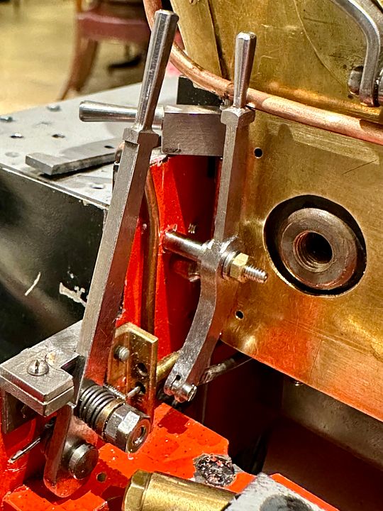 I have tried to maintain the style of Ian Jaycocks’ work with these new components. Tim |
|
cfmrc
Seasoned Member
Posts: 107
|
Post by cfmrc on Feb 5, 2024 18:06:55 GMT
The central trap door on the Sir Sagramore ashpan now has a control / locking device. It’s a bit unorthodox but it will hold the trap door shut when running. 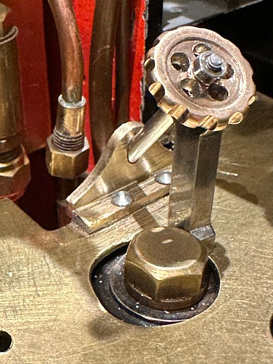 The linkages ended up with a rod pointing backwards at 45deg from the base of the footplate, with it pulled up to close the trap door. I therefore made a steel toggle that holds the rod in the open position: 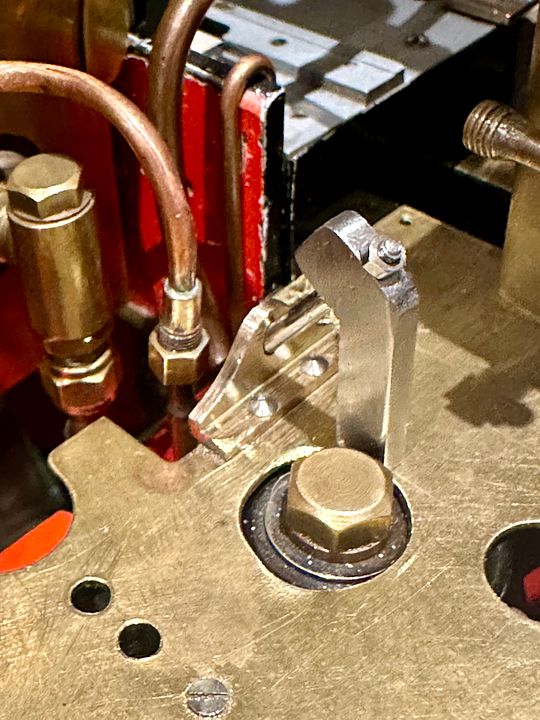 It rotates 90deg. and pushes in towards the backhead to open the trap door for ash disposal: 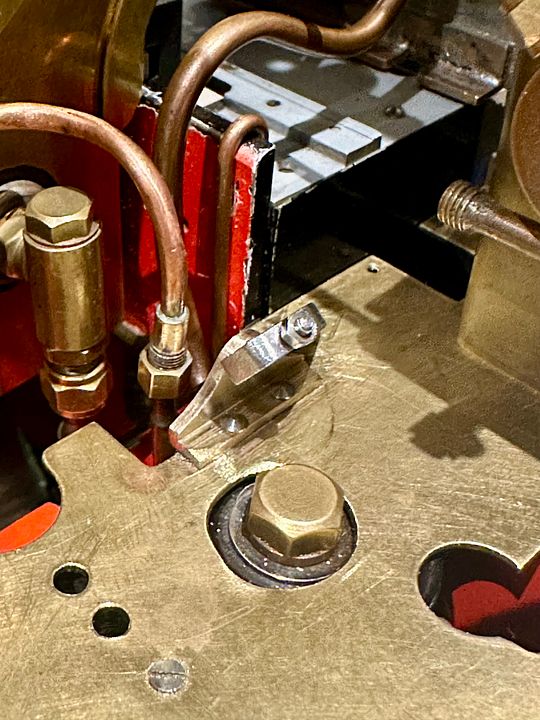 I wasn’t convinced by the appearance of the toggle and it was also a bit slippery to handle. I therefore made a hand wheel to make it easier to hold and also reduced the locking pillar in size. The wheel was turned as a blank and mounted on a mandrel, Loctited in place. This was then drilled on the rotary table. 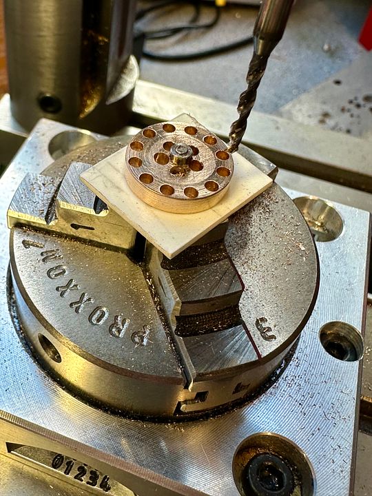 The outer ring was then turned off to give the ‘grippy’ outer part of the hand wheel. 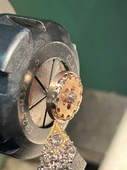 After rounding off the edges the front face was given a rebate using a graver. 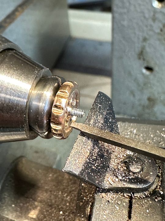 The locking toggle components can be seen here, before assembly. The hand wheel was simply soft soldered onto the steel toggle, and held in place with a 10BA nut, with it pivoting freely on the rod - a piece of coat hanger suitably turned down & threaded. 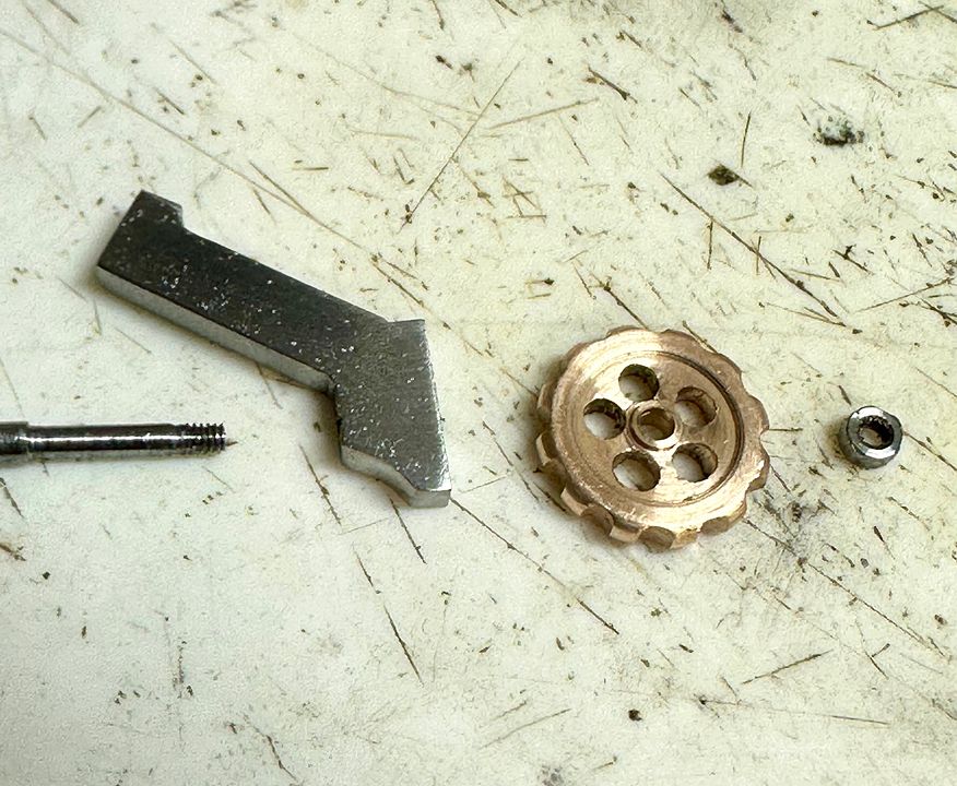 Finally an exciting video showing it in action! youtube.com/shorts/W-L1sNSK0to?si=oaF4_MGQ-JlfjyT9Back to small scale stuff now. Tim |
|
johan
Active Member

Posts: 26
|
Post by johan on Feb 5, 2024 19:52:17 GMT
This is just to drool about... Really excellent work.
|
|


