|
|
Post by ericcee on Jul 9, 2006 20:15:11 GMT
I've had a good weekend in the workshop - over 10 hours! So I've been able to complete the assembly of the Hackworth valve gear and the brakes (one axle only). And I've hit a couple of snags:-
1 - The weighshaft seems too short by 2-3 mm because the heads of the cap screws that lock the return cranks on to the crank pins interfere with the vibrating levers (well, they just skim the levers). It would easy enough to file/grind a few thou off the heads, but I'll leave them for the time being. The main problem is that there is no positive lateral location for the weighsaft, other than the vibrating levers and radius rods.
2 - The die blocks are a sloppy fit in the slides which means that it is almost impossible to set the valves correctly. When set correctly in full forward gear, they are quite a way out in full reverse. And there's quite a bit of valve travel in mid gear - sufficient to open the forward inlet ports. Surely this can't be right?
I'll attempt to contact MW tomorrow to see what they advise and I'll report back.
I shall also endeavour to get some photos up here tomorrow - I think I've worked out how to do it!
Eric C.
|
|
|
|
Post by ericcee on Jul 11, 2006 16:32:06 GMT
I spoke to Debbie at MW yesterday morning and these were her responses:-
- The Weighshaft -
She seemed concerned at my comments about it being a mite too short and having no means of fixing it laterally, so she will pass this on to the design team. In the meantime, I'll grind down the heads of the cal screws.
- Sloppy Dieblocks -
She will send me a couple of replacements. There are also some modifications being prepared to improve the valve timing, including replacement axlebox springs! These will be sent to me.
- Motion Bracket hitting Connecting Rod -
Modified motion brackets are on their way.
- Missing Reversing Lever Latch Spring -
She'll get the packing list corrected and will send me a spring.
So - I await these developments with interest. I must say that my contacts with the MW staff so far have been most friendly and helpful.
Eric C.
|
|
|
|
Post by ericcee on Jul 11, 2006 18:25:50 GMT
OK - I've had my dinner, washed down with a glass or three of a rather good Bordeaux from Sainsbury's, so I'm fully recovered from the hassle of getting a few photos into the photobucket and I'm ready to show progress so far. Let's start with an overall view:- 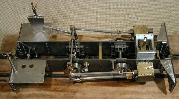 It's already getting quite heavy! As you can probably see, it's built like the proverbial tank - there's a total of 80 M6 nuts and bolts just holding the basic frames together! The next shot is a closer view of the weighshaft showing the lack of any positive lateral location. (I've just consulted my copy of the Sweetpea book by Jack Buckler to see how he tackled this issue - it "runs" in a tube with the slides at either end preventing any sideways movement - a much neater solution than the one here). 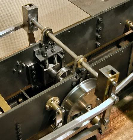 Then a couple of views of the return cranks to show how the cap screws interfere with the vibrating lever. 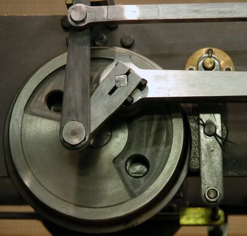 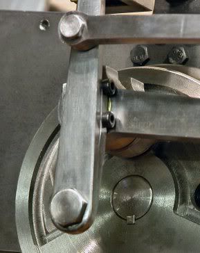 And finally, a couple of views of what I can only describe as the "exhaust manifold" - a couple of chunks of nicely machined brass (?) that clamp around the cylinder exhaust and blast pipes. They are sealed with Foliac graphite. This is (to me) an unusual approach to teeing the exhaust pipes - I look forward to seeing how it works out in practice. From above:- 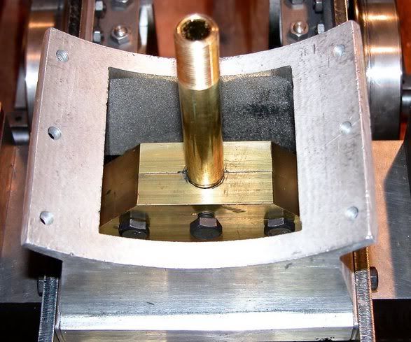 And from below:- 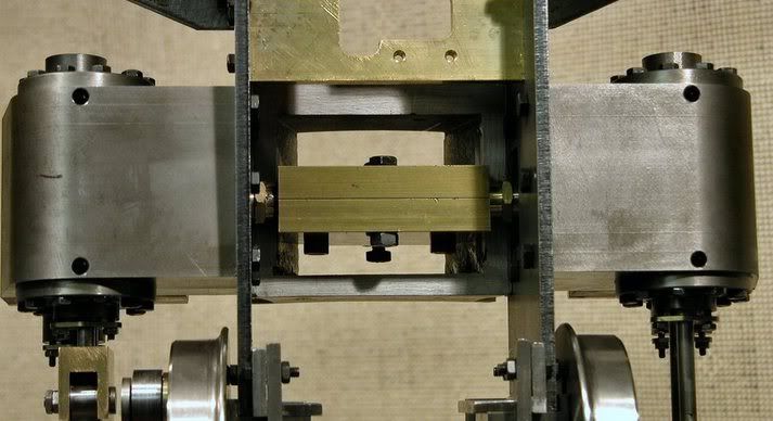 I wish I'd taken a photo of it before assembly and before I'd fixed the smokebox saddle - I won't be taking that off again if I can avoid it as it was more than a bit of a fiddle to get all the bolts in! I forgot to mention in my last post that Debbie at MW suggested that I open out the PTFE glands with a round file! I don't like the sound of that, so I'll be digging around in my collection of reamers to see if I have any the correct size for the piston and valve rods. And, of course, I'll have to take a lot of the thing to bits again! Later Update - I've just realised that I'll have to take the smokebox saddle and the "exhaust manifold" off to be able to remove the cylinders so that I can open up the dreaded PTFE glands - oh woe is me!So - this is the Bagnall up to Kit 5 and, including all the fiddling about with the stiffness, it has taken less than 35 hours. What did I say in another thread about buying time? I have ordered Kit 6 for delivery next week. Eric C. |
|
|
|
Post by ericcee on Jul 11, 2006 19:08:05 GMT
I mentioned the Sweet Pea book in this last post - I "fell in love" with this little engine some years ago but it was after reading the book and talking to the guys at Blackgates that I realised that I simply did not have the time (or the ability?) to acquire the skills necessary to build even such a "simple" loco from scratch. Hence the decision to build from kits - I want to be able to enjoy playing with one while I'm still fit enough! As something of an aside (now that I've cracked this photo posting palaver) I'm including a photo of my Maxitrak Jack (called Isabel after our first granddaughter). 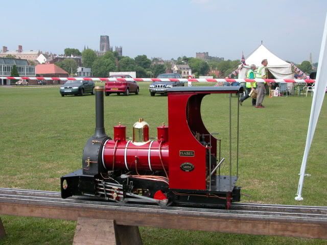 The photo was taken on the portable track of the Sunderland MES at the Durham Regatta (see the thread I started on Risk Assessment). On the skyline, from left to right, you can see the prison, cathedral and castle - quite a view! This was a most enjoyable and rewarding event, one of many instances justifying my decision to get something up and running as quickly as possible. I reckon I'll be making references to this engine when I come to tackle the painting of the Bagnall (painting Isabel was quite a challenge!). By the way, the Bagnall will be called Hannah after our second granddaughter! My wife wants to know what I'll be doing if we have any more grandchildren - building a traction engine? Eric C. |
|
|
|
Post by ericcee on Jul 14, 2006 15:05:18 GMT
I believe I've identified the cause of the "stiffness"!
Yesterday, I removed both sets of valve gear and the connecting rods, just to prove (yet again) that there is no problem with the quartering - the chassis rolls under finger pressure in this condition, so there's no problem there.
I then removed the RH cylinder and, on a clean workbench, removed the rear cylinder cover. I was surprised to realise that the cover moved quite freely on the piston rod, so that PTFE gland is not the problem! The piston is relatively stiff in the cylinder, which is no bad thing and is caused by the CI piston rings (I ensured that the piston was a good running fit in the cylinder before I fitted the rings). Similarly, the valve rod runs reasonably freely in its gland. The slide bar seemed a bit rough (why haven't I spotted this earlier?), so I popped it in the lathe and polished it with some fine emery.
Today, I started on refixing the RH cylinder, checking things step by step. Before I tightened the motion bracket, things were still running freely - only slight downward pressure was needed to roll the chassis back and forth. But, as soon as I tightened the bracket bolts, everything seized up again. Investigation showed that the tightened bracket is pulling the slide-bar in by about 0.6mm - enough to put things right out of kilter.
I removed the RH connecting rod again, put the LH one on and, with the LH motion bracket fully tightened, everything still runs quite freely.
So, only the RH motion bracket is at fault (in relation to the RH cylinder, at least). I wonder if I should swap them round ...? In any event, it would be quite easy to pack it out with a piece of shim, or appropriate washers, but I will leave it until the next package comes from MW next week.
I'll keep you posted.
Eric C.
PS - Am I still the only one here building the Bagnall? I wonder how many they've sold?
|
|
|
|
Post by ericcee on Aug 7, 2006 17:21:57 GMT
It's been a while since I last posted here - various domestic matters and a short family holiday have got in the way - but I have been doing some work on the Bagnall.
Kit 6 - the smokebox, front-end pipework and lubricator - arrived on 19th July and I've taken things as far as I can until the problems with the valve gear are sorted out. There were a few inconsistencies between the instructions, the parts list and the actual bits, but a little bit of head scratching soon had them sorted out.
A phone call to Debbie on the 27th July (to remind her that the replacement die-blocks and other bits had not arrived) resulted in me ordering Kit 7 (the boiler - the expensive bit, equivalent cost-wise to two kits), for delivery on my return from holiday.
The boiler arrived this morning and, to my untutored eye, looks pretty good. It's been thoroughly cleaned up and has all the relevant CE markings and certification. But still no die-blocks! The ones I have are about 12.8 mm wide, while the slides average (!) 13.1 mm - no wonder there's a lot of slop. So, a phone call to Debbie resulted in another promise to put replacements in the post. She also told me that the valve gear "has been redesigned" and will go into production "this week".
Meanwhile, there's not a lot I can do until the valve timing is set. The steam pipes go straight from the smokebox to the steam chest covers, so removal of the covers will involve quite a bit of dis-assembly - not something I want to do more than necessary! I've spent an hour or so this afternoon shortening the bolts that fix the smokebox to the saddle - they are way overlong and protrude into the smokebox. There's enough clutter in there to make cleaning difficult without having to negotiate redundant lengths of bolt!
Later this evening, I'll post a photo of the "exhaust manifold" that I've mentioned before, since I had the opportunity to take a few when I had to remove the cylinders.
|
|
|
|
Post by ericcee on Aug 7, 2006 17:41:03 GMT
Photos as promised:- This first is of the parts that make up the "exhaust manifold". The two chunks of brass clamp around the exhaust pipes - most unusual (to me). 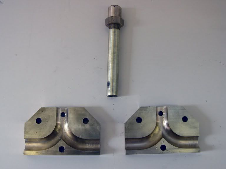 And two photos of the smokebox - it seems to be turned from a large chunk of stainless steel (the saddle is an aluminium casting). 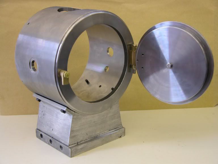 I'm not impressed with the door fittings - they aren't very prototypical! 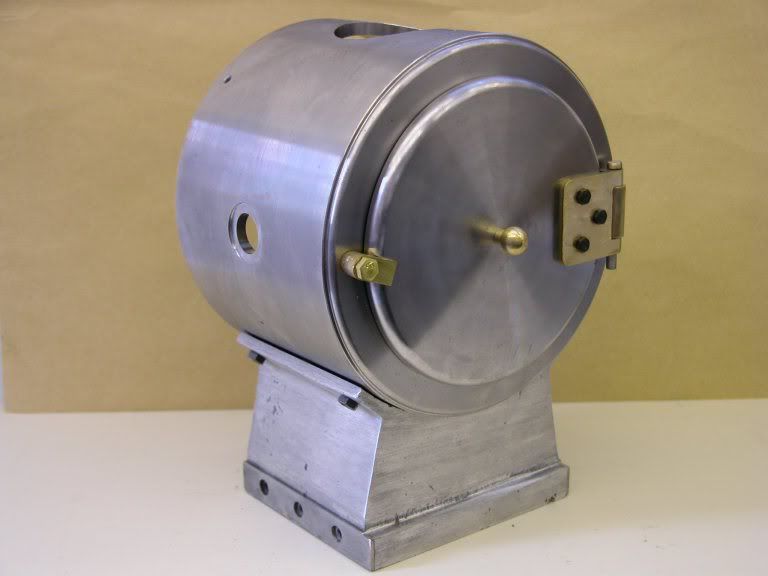 By the way - is anybody interested in all this? And am I still the only one on this forum building the Bagnall? |
|
|
|
Post by spurley on Aug 7, 2006 21:10:21 GMT
Hi Eric Please keep posting! I am not a Bagnall nor a Modelworks builder. I am building a 3.5" Tich, but what you are describing and showing is very interesting, to me at least  I take a very keen interest in postings on this site and it never fails to amaze me the amount of interesting and diverse things that we, as a group are involved in. Cheers for now Brian |
|
|
|
Post by ericcee on Aug 7, 2006 22:04:31 GMT
Thanks, Brian - I'll keep 'em coming!
I have a mind to get some photos of the front-end to illustrate my comments about not wanting to dis-assemble the pipework too often for valve setting. I'll have to trial assemble the pipework anyway as it will need some adjustment/fitting and it will be easier without the boiler in the way.
Eric
|
|
|
|
Post by ericcee on Aug 14, 2006 18:20:44 GMT
It's me again! I've trial-fitted the front-end pipework and taken some photos, included here. These will illustrate how the steam pipes go into the top of the valve chests - and how their removal for valve-setting will be quite involved. The first two show a front elevation:- 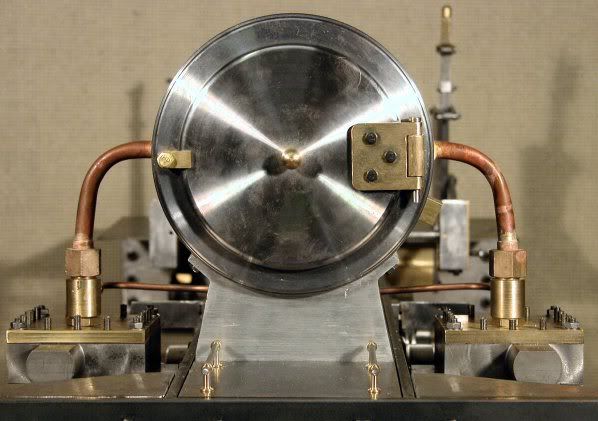 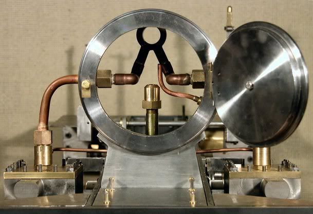 Then from the rear - the lubricator pipes are in place:- 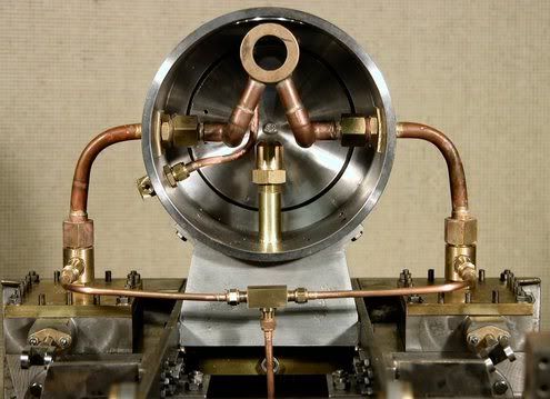 And a side elevation of the smokebox:- 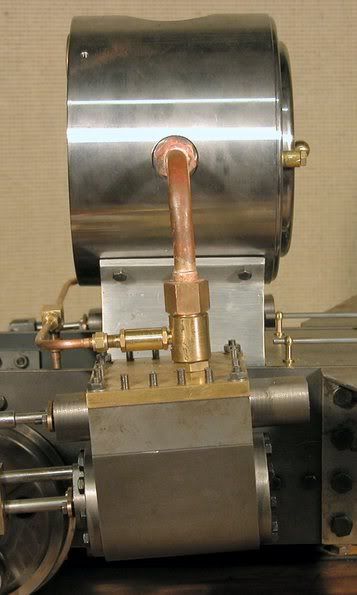 And finally a view with the boiler temporarily in place - just to make sure it fits! 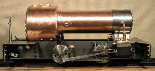 As you can see, I've removed all the valve gear bits, and I'm still waiting for the replacement die-blocks. I suspect that the corrections to the valve gear are quite extensive - and include new die-blocks. All in all, I'm getting just a bit nervous - this sort of thing should not happen. Why don't they build a complete loco before they start selling it? This must be what Maxitrak do; the Jack I built was the third or fourth off the line and I had absolutely no problems with it (other than those of my own making). Am I being unduly pessimistic? Eric |
|
|
|
Post by baggo on Aug 14, 2006 19:22:29 GMT
Hi Eric,
Nice photos, keep them coming. I see what you mean about the smokebox door fittings-that hinge is absolutely awful!
I can understand your concern about incorrect and badly fitting parts. As I commented on JJ's Britannia thread, if they are building control models why are they still having so many problems? I can only assume that they are not actually keeping up with the kits they are sending out so they are not finding the problems themselves first. As you suggest, they should complete and test each model before they put them into production.I don't want to be critical as I think Modelworks and the staff are doing a great job but they really have to get their act together when it comes to production methods and quality control. It will be interesting to see how the new Duchess compares to the previous models in this respect.
John
|
|
|
|
Post by Deleted on Aug 14, 2006 20:22:00 GMT
I agree that the faults in the geometry of the motion on the Bagnall and Britannia are disappointing - particularly on the Britannia since it is meant to be a well proven design. At least they seem to be sorting the problems out. Mine looks pretty good now, and I'm taking it to Modelworks on Wednesday to test on compressed air.
I saw quite a batch of Bagnall boilers when I was in Daventry a month ago, so they must have sold a reasonable number. Hopefully now they've done the Bagnall boilers they'll get on with the Britannia ones!
Regards, John
|
|
|
|
Post by ericcee on Sept 1, 2006 19:12:42 GMT
Isabel from MW called yesterday to tell me that Kit 8 (firebox and pumps) was ready to be shipped. I don’t know if it had just been prepared or if they were chasing me to spend some money (it’s just over three weeks since the Kit 7 (the boiler) was shipped).
(By the way, she told me that Debbie is out of action for a couple weeks - into hospital for a minor operation and then recuperation. I'm sure we all wish her well.)
The kit duly arrived at 1:30pm today, courtesy of City Link, and I was amused (bemused) to see that they had included a note to the effect that Kit 8 was being shipped before Kit 7 due to a delay in the supply of the boilers (see John’s message above).
I’ve assembled the firebox (remember that it is a marine type, so it is quite separate from the boiler) – it is quite nicely made from stainless steel, with the equivalent of a firebrick arch at the front-end, but the various hinge blocks (fire-door and damper) seem badly machine and needed quite a bit of fettling to get them to fit properly. I also assembled the hand pump – I’m not too happy about some of the details of this, but I’ll reserve judgment.
I’ll try to get some photos posted early next week.
TTFN
Eric
|
|
|
|
Post by ericcee on Sept 17, 2006 16:07:08 GMT
I suppose it is just possible that someone out there may be wondering where I've been in the last couple of weeks. The truth is that not a lot has happened and there's not much to report.
I completed the axle-pump without problems until I came to fit it in the frames. I soon discovered that the eccentric was slightly out of line with the pump, causing it to seize at full stroke. While I was figuring out how to fix this, I started to grumble about the lack of accuracy at the MW factory - and then I remembered that I had fixed the eccentric on the axle. A few minutes later, after this blindingly obvious revelation, everything was fine and smoothly working! I had confused this with my Maxitrak engine, where the axles came with the wheels attached, axleboxes in place and the fly-cranks fixed and quartered, and the pump eccentric in place. Just goes to show how stupid some kit-builders can be - eh?
Anyway, before I could get the photos taken, as I promised in my last post, I had decided to strip everything back to basics so that I could re-assemble all the motion (yet again), while checking very carefully, step by step, to ensure that I had not done anything wrong. I've just spent a couple of hours completing this, and attempting to set the valve timing and I'm back to square one. The engine will still not work, as even I can see that the valve events are a mess - valves should not open in mid-gear, for example! The sloppy die-blocks (not yet replaced) don't help, of course.
By the way, should the slides on Hackworth gear be vertical in mid-gear? They are not vertical on this engine - and if they should be, either the reach-rod is too long or the mid-gear notch is in the wrong place on the reverser quadrant. The only thing I haven't done - yet - is to try to set the valves with the boiler and all the other top-hamper on board. It could make a difference as there seems to be too much movement under the springs of the rear axle (stiffer springs have been promised by MW).
Can anyone out there advise me on a source of information on the geometry of Hackworth gear? I feel I ought to understand the finer details better than I do at the moment.
I called MW last Wednesday to check on progress of the VG mods and the next kit, and spoke to Debbie, but she was so obviously trying hard to catch up with things after her absence, I didn't have the heart to push her on this. Perhaps I'll try again in another week or so.
I am trying to convince myself that everything will work out OK in the end! Have faith, I say!
Nil desperandum.
Eric
|
|
|
|
Post by baggo on Sept 17, 2006 16:47:40 GMT
Hi Eric, Have you downloaded a copy of the valve gear simulation software by Charlie Dockstader? If not you can get it from: www.tcsn.net/charlied/It's a brilliant piece of software and has working simulations of virtually all the valve gears. You can also change all the parameters for designing your own or perhaps checking out other peoples designs to see how good (or bad ! ) the valve events are. It is a bit fiddly to do that though. I'm pretty sure that the slides should be vertical in mid gear otherwise the forward and reverse events will not be equal so it sounds like something is not right there  You will get some movement of the valves in mid gear due to the design of the gear and it may well be enough to actually open the valves. This is the case with most valve gears and the loco may well run in mid gear once it's moving. Don't get disheartened!  John |
|
|
|
Post by ericcee on Sept 17, 2006 18:32:05 GMT
Thanks for this, John.
I had a version of this software on my PC two or three upgrades ago - then lost it and completely forgot about it. A simple google search would have found it if I had had my thinking cap on.
I've now downloaded it and have been playing with it, although - as you say, it could be a bit fiddly changing dimensions. I shall give it some careful thought.
Incidentally, it does show the slides in a vertical position in mid gear.
I was basing my statement that the valves should not open when in mid gear on my experience with the Walschaerts gear on my Maxitrak loco. I assembled this, setting the valves - once - as per instructions, tested it on air and it worked perfectly first time - I've not touched the valves since. This is how it should be, don't you think?
Thanks again.
Eric
|
|
|
|
Post by baggo on Sept 17, 2006 19:20:11 GMT
Hi Eric,
I've just had a look at my copy of ' Model Locomotive Valve Gears' by Martin Evans. In the description of Hackworth gear he says that the slides should be exactly vertical in mid-gear. The valve movement in mid gear should be twice Lap plus Lead as for Walschaerts'. If the gear is designed to give zero lead then the ports should not quite open. If the gear is designed to give lead then the ports will open by the amount of the lead which will probably be about ten thou or so.
It is interesting to read your comments on the Maxitrack loco. We don't seem to read about problems with Maxitrack or Polly locos. I wonder why.
John
|
|
|
|
Post by ericcee on Sept 18, 2006 10:50:24 GMT
John,
I feel like a real idiot - your mention of Martin Evan's book sent me scurrying to a box of books I inherited from a good (late) friend a few years back. And, lo and behold, there was a copy of the very book (15/- in 1962!) - I really should know what I've got hidden away.
Nevermind, I shall now read and digest the Evans words of wisdom. I had a vague idea of what lap and lead were about, now I have a much clearer idea. It could be quite a challenge (for me) to measure these on the Bagnall - and where will it get me if I can? I guess at best it will enable me to talk with some degree of intelligence with the people at MW - if I ever get through to the right people!
The absence of problems on Maxitrak and Polly locos is, I reckon, easily explained - they have good, consistent production facilities for designs that have been proved before release. And they are working within their capacity!
Thanks, yet again, John. (This forum is certainly very valuable to tyros like me!)
Eric
|
|
|
|
Post by ericcee on Sept 19, 2006 14:47:47 GMT
Having read and partially digested the Evans words of wisdom it may be worth quoting him here, on the subject of Hackworth valve gear:-
"... it cannot be recommended for model locomotives as unless the eccentric rod [what I've been referring to as the "vibrating lever"] is made very short, trouble may be experienced in obtaining sufficient clearance for the guides underneath the boiler. At the same time, if the eccentric rod is made short, the valve events suffer. Another disadvantage of this gear is that the vertical movement of the axleboxes in the horns upsets the valve timing to some extent."
I wonder what the myriad of Sweet Pea owners would say about that?
This thought prompted me to go back to Jack Buckler's book on the Sweet Pea to see what words of wisdom he had to offer on valve setting. The most significant point he makes (in my opinion) is that the first thing to do is to set "the rear axle ride height so that the slide block is exactly in the centre of the slide with the engine on front or back dead centre."
He goes on to describe the various compromises that have to be made with this gear, and it all seems very logical to me.
His advice is, interestingly, completely the opposite of the MW instructions, which start by telling you to put the loco up on blocks. Instinct told me that this was wrong, but I persevered anyway, with the results I've described. So, as I hinted a couple of posts ago, I reckon the only way to set the valves is with the whole loco at its "operational" weight.
All of which is academic until I get the relevant mods from MW - and a new set of slides (die blocks) that actually fit the guides!
This thread is turning into something of a Baggo/Ericcee exchange (and none the worse for that, I guess) and has been going on a bit! So I shall pipe down until there is something more postive to report.
But ... before I do, I must have a few words about Baggo's Mickleover. In the mid 60's I spent a miserable few weeks in digs there (in December, with no car) when I first went to work for Rolls-Royce Aero Engines. This was countered a few years later when I spent a peasurable few days at the RR Training School learning about Tyne gas turbines and variable pitch propellers from a Pilot's point of view. Not that I was (or ever have been) a pilot - if they didn't have enough pilots, RR would send a bunch of us computer techies up to Mickleover to keep the tutors busy!
TTFN
Eric C.
|
|
|
|
Post by standardsteam on Sept 20, 2006 8:31:46 GMT
This thread is turning into something of a Baggo/Ericcee exchange (and none the worse for that, I guess) and has been going on a bit! So I shall pipe down until there is something more postive to report. I am following with interest, maybe have a separate thread relating to the valve gear as it seems to be quite involved. I follow build sequences of engines with interest, whether I happen to be building that type or not! |
|