chiptim
Part of the e-furniture

Posts: 270
|
Post by chiptim on Apr 5, 2009 19:33:11 GMT
I started Model Engineering in October 2007. I hadn't proposed to put any images on the web but it's great to see other peoples work and share etc so here goes! Hopefully it may inspire other newcommers - I've achieved this with a low budget. All the turning and milling has been done on my lathe, an ML10. It doesn't look much I know but it's taken me ages to get this far. I'm hoping to get the cylinders mounted on the frames with connecting and coupling rods etc and then move on to the boiler over the summer months. I'll just put a few photos on to begin with to make sure I'm doing it right. Here's my workshop. It's just under 2m x 2.5m. 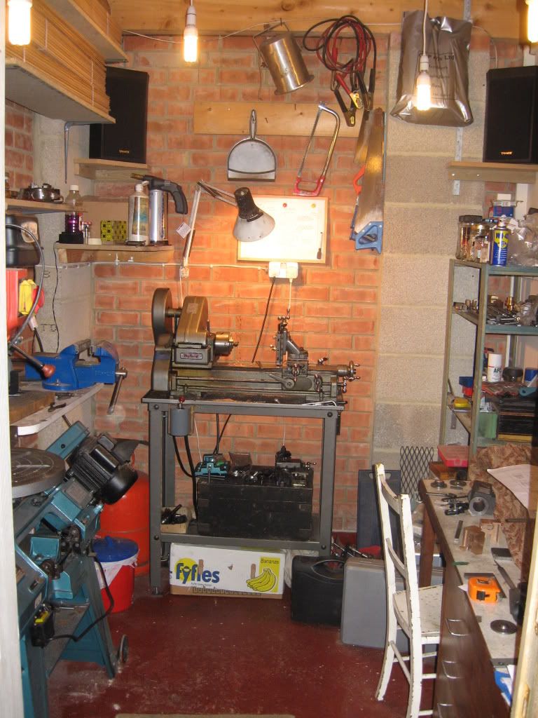 This is my progress so far: 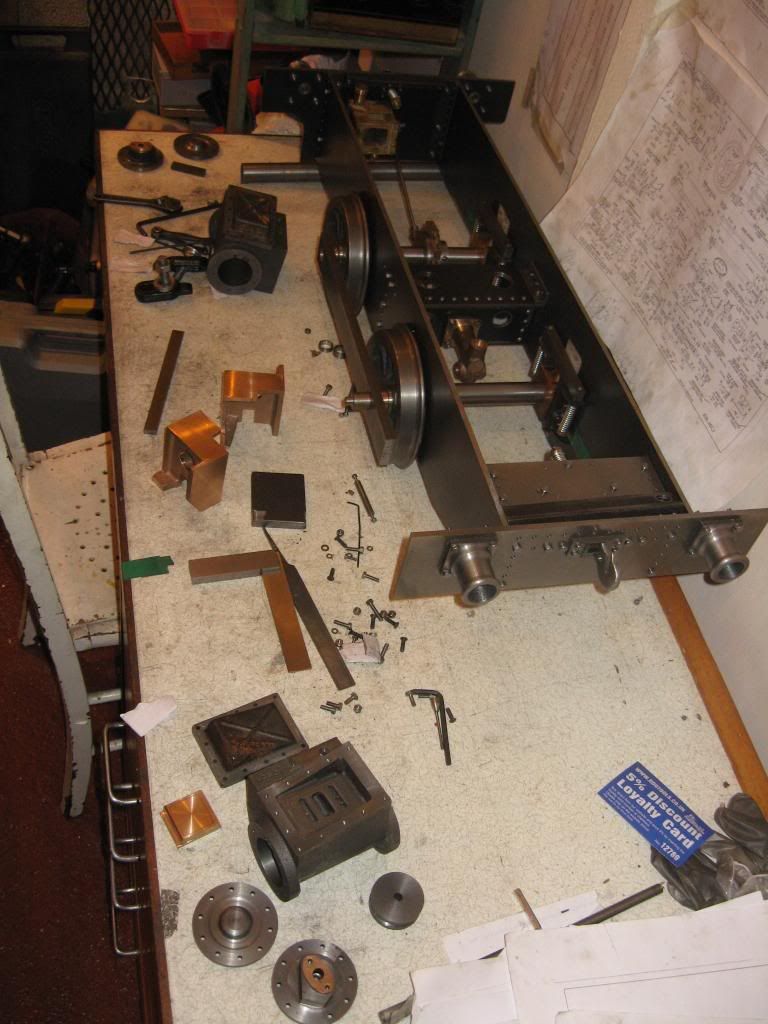 Machining the crossheads 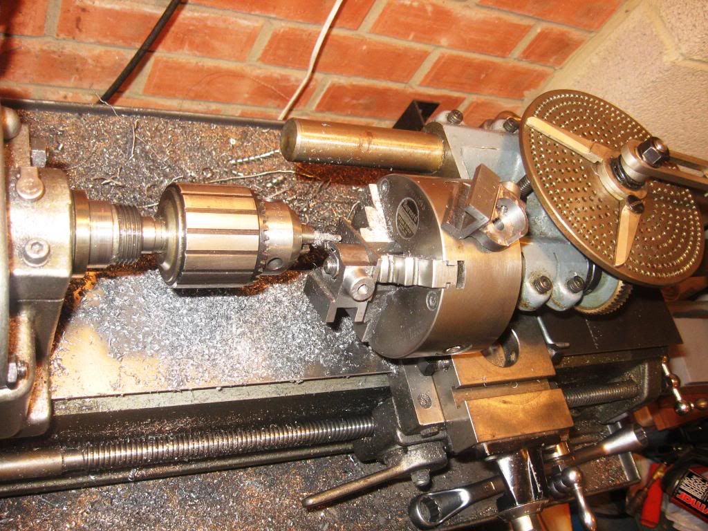 ...and the big ends. Despite discussing that I wouldn't make them split, I changed my mind as it wasn't a lot more work. They're not finished yet. 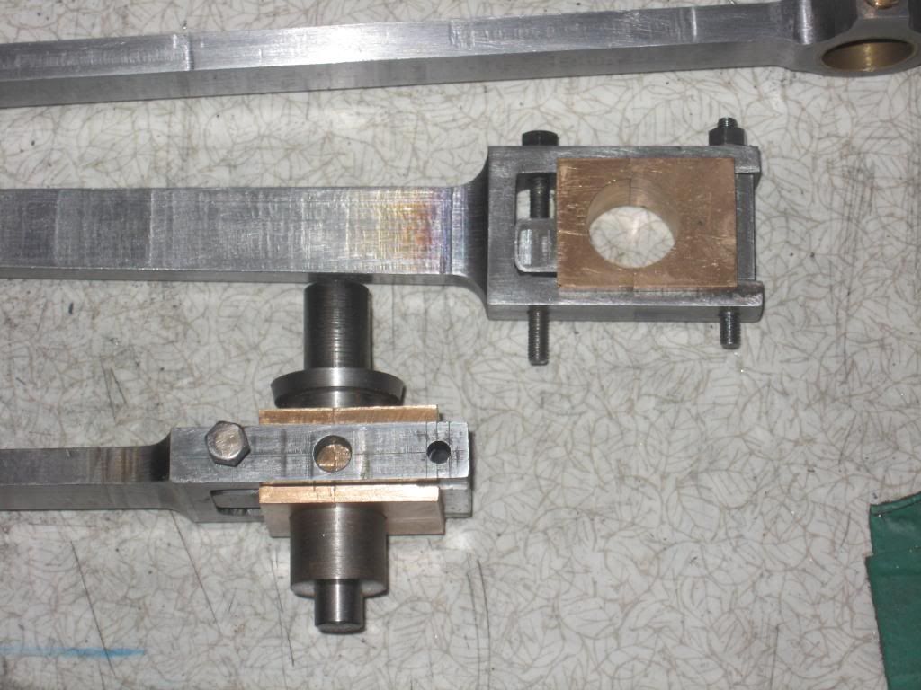 Regards Tim. |
|
|
|
Post by jgb7573 on Apr 6, 2009 9:22:21 GMT
Nice work. Thanks for sharing these with us.
|
|
|
|
Post by welshy on Apr 9, 2009 16:16:03 GMT
looks excellent, and well engineered, a lot more work doing everything in the lathe as well.
keep up the good work.
I look forward to seeing more photos of your progress.
Mike
|
|
|
|
Post by engineernut on Apr 9, 2009 17:00:09 GMT
Nice bit of maching there.  I see you are a customer of RDG as well, with their loyalty card in the pic. ;D |
|
chiptim
Part of the e-furniture

Posts: 270
|
Post by chiptim on Apr 9, 2009 20:19:19 GMT
Generally I'm happy with my work although sometimes I rush it to get results and then get annoyed with myself.  I did take great care with the cylinders and pistons. The port machining and steamways are less well done but I think they'll function OK and most of all I didn't mess up and have to buy another casting! Machining a cylinder block bolted to the vertical slide on an ML10 puts the lathe at its limit and is not ideal as well as giving me backache but the pistons slide evenly in the bores so I'm hopeful of producing a runner... I used a 1" bar between centres with the cylinder bolted to the cross slide. 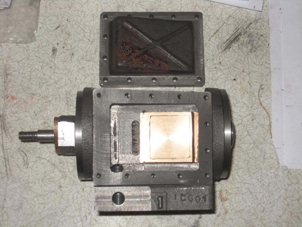 I'll try and get some better photos when the cylinders and connecting/coupling rods are all fitted. Tim |
|
kingsteam9
Hi-poster
  Enter your message here...
Posts: 160
|
Post by kingsteam9 on Apr 10, 2009 8:19:45 GMT
Tim,
I've got to tell you that as a fellow ML10 user I admire what you've achieved here - no mean feat with this machine. How did you cope with milling the rods?
Robin
|
|
chiptim
Part of the e-furniture

Posts: 270
|
Post by chiptim on Apr 11, 2009 7:31:28 GMT
Robin,
I removed the tool post and clamped them to the cross slide with suitable packing. The problem is the slide isn't enough so you have to reset 2 or 3 times. This leaves the marks you can see in the photo but they can be removed with a fine file and wet and dry.
Tim
|
|
kingsteam9
Hi-poster
  Enter your message here...
Posts: 160
|
Post by kingsteam9 on Apr 13, 2009 17:21:37 GMT
Tim,
Thanks - I thought that might be the method to use. Best of luck with Jessie, and look forward to seeing more photos.
Robi
|
|
chiptim
Part of the e-furniture

Posts: 270
|
Post by chiptim on May 8, 2009 18:17:55 GMT
A bit out of sequency but I just found this photo of the cylinders being bored. The between centres bar is 1" Dia with a 3/16" Dia tool steel cutting bit held with a single screw. For the final cuts, I pushed the bit out slightly too far and stoned down to length taking regular measurements. Bores finished off with a honing stone as described on the Polly website. I'm very pleased with the final result. The cylinders and pistons are my finest work to date. 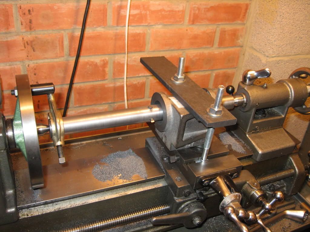 Regards Tim. |
|
simonwass
Part of the e-furniture
 Cecil Pagets 2-6-2 of 1908. Engine number 2299. Would make a fascinating model....
Posts: 474
|
Post by simonwass on May 8, 2009 22:49:43 GMT
Looks from the pic that you are running the lathe in reverse? If so, be very careful with cuts & feeds as too much pressure can cause the driveplate to unscrew itself off the end of the mandrel. It isn't as dangerous as a chuck coming free but it could be embarrassing.
Nice stout boring bar there, one of the reasons you got a good result. For fine tuning the cutting bit use a grubscrew behind the bit and by knowing the tpi you can jack out the bit by quite small amounts.
|
|
chiptim
Part of the e-furniture

Posts: 270
|
Post by chiptim on Jun 15, 2009 21:23:26 GMT
Thanks Simon. A grub screw would have been useful behind the cutting bit and a worthwile mod for next time... Since then I've finally managed to get the motion bracket, coupling and connecting rods and cross slide mounted on the frames. I'm going to leave it at this stage and move on to the boiler as I'm keen to get this made during the summer months when I can solder outside and have the benefit of the extra 15 degrees or so compared to winter! The photos didn't come out too well. I finally found the camera in the bottom of the laundry basket (little people been fiddling) and I couldn't persuade the flash to work, so they're a bit grainy. It amazes me how the photos are able to make so many hours of work look like such little achievement! 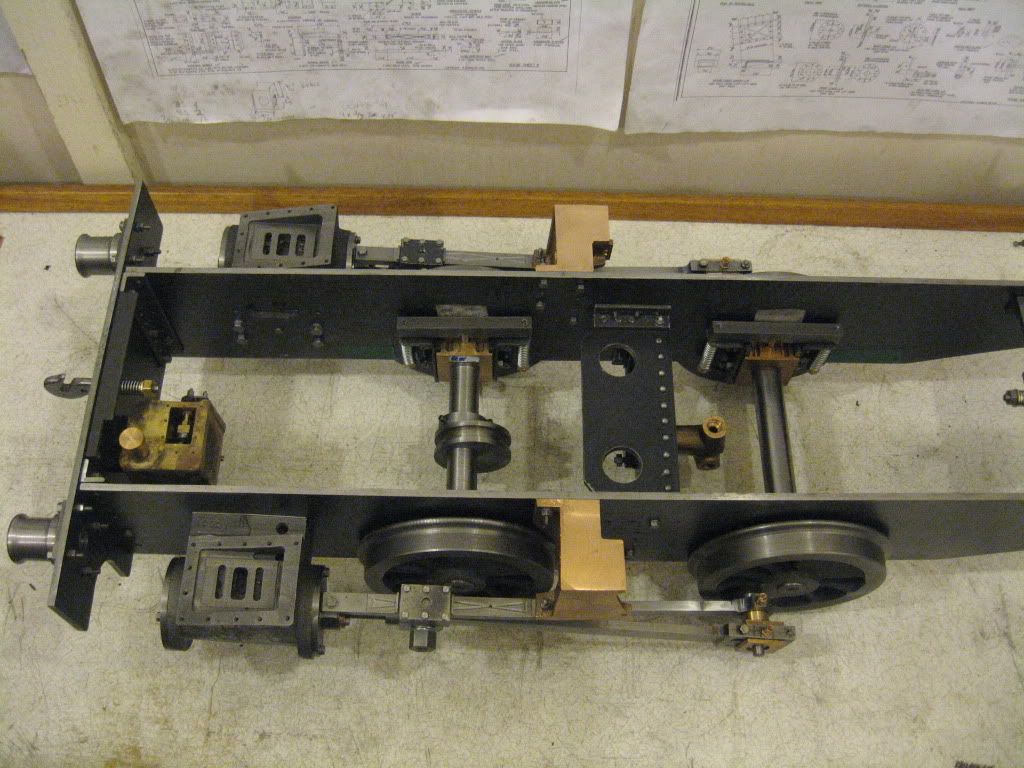 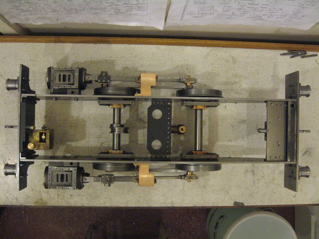 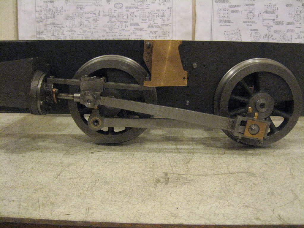 You can see I've started work on the boiler. Fortunatly the plates were ready flanged but I've drilled them and even had a go at the inner rapper. It amazes me how much heat is required just to anneal this piece of copper! 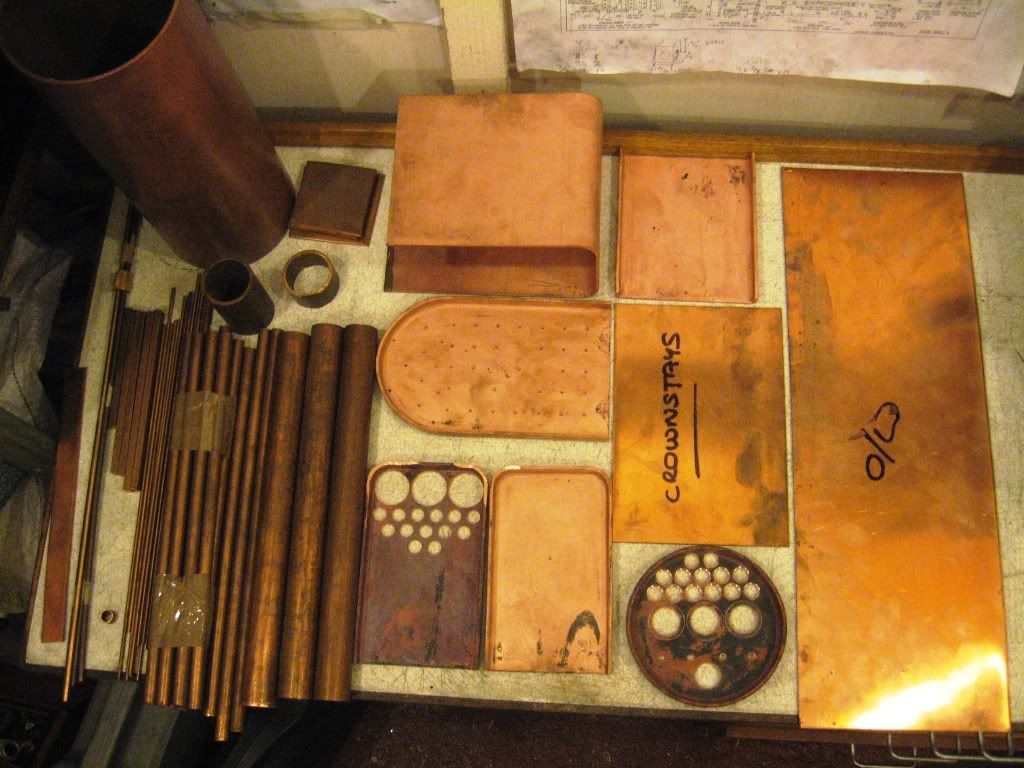 Regards Tim. |
|
|
|
Post by Shawki Shlemon on Jun 16, 2009 10:24:33 GMT
Nice work ,sure you need a lot of heat , an extra pair of hands with another source of heat makes live easier . Good luck with the boiler .
|
|
chiptim
Part of the e-furniture

Posts: 270
|
Post by chiptim on Oct 15, 2009 20:46:56 GMT
I've just been looking at JB's fantastic Brit Boiler and remembered I'd started this thread that I've not updated for a while. The boiler is almost ready for the two halves to be inspected. Some of the joints that I thought would be easy have been a challenge like the barrel to outer wrapper and throat plate. I had to have a few goes at it and it's not a pretty site - functional describes it. The crown stays I wasn't looking forward to but they turned out simple first time. 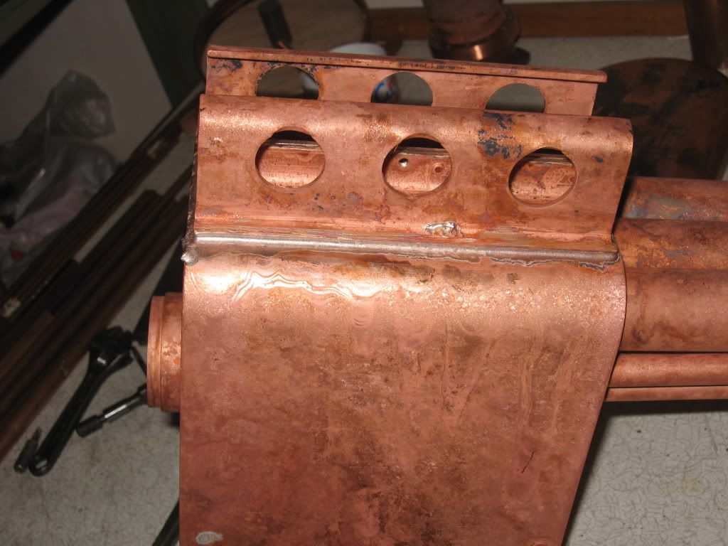 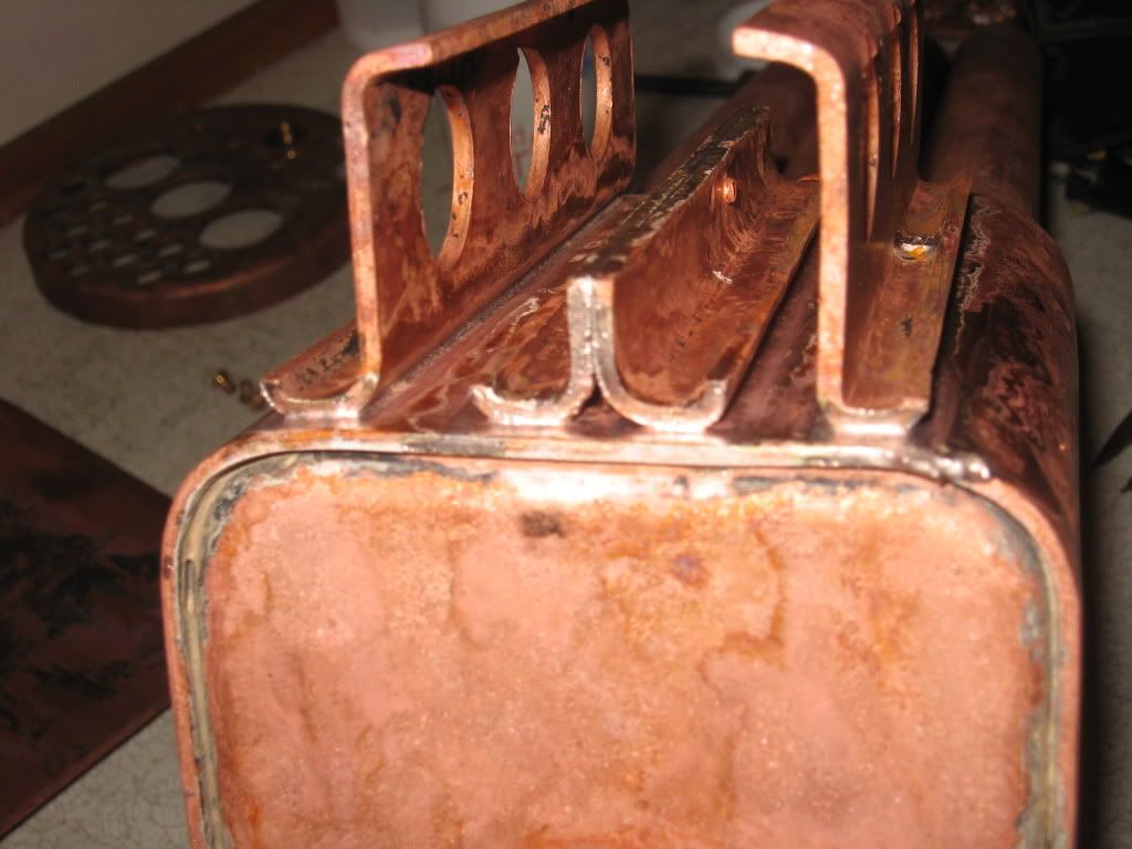 Having soldered on the crown stays, I checked the fit. The firebox is resting on a piece of foundation ring. Of course the tubes can be bent up or down slightly to get the crown stays in contact with the outer wrapper along their length but I want the the gap around the firebox as uniform as possible. 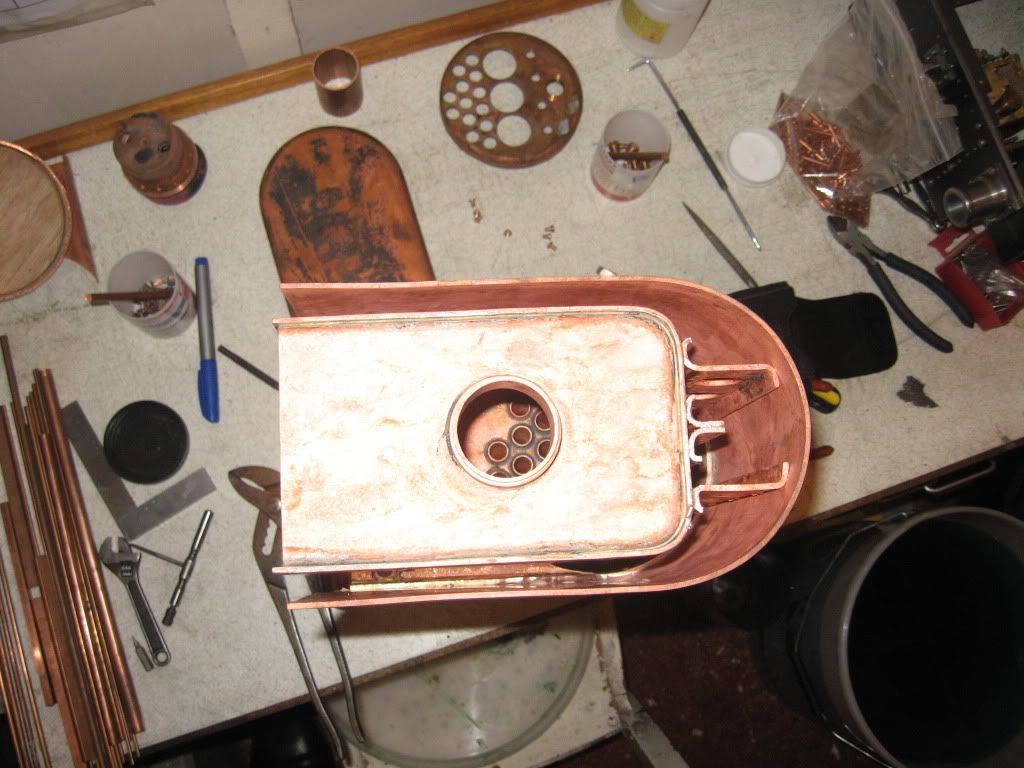 Tim |
|
simonwass
Part of the e-furniture
 Cecil Pagets 2-6-2 of 1908. Engine number 2299. Would make a fascinating model....
Posts: 474
|
Post by simonwass on Oct 15, 2009 22:35:31 GMT
Some nice silversoldering there.
I'd have a look at the bit at 9'clock on the top left of the doorplate.
Did you not think of putting in the side stays before silversoldering in the doorplate? Makes the stays a doddle as you get more air in for the flame, once doorplate is in theres only a few stays at the back to do and as they are close to the open end they are easy. Cyclone burners and oxy gear make stays easy but without the doorplate its much better as theres also more room to see and work.
It seems the norm to put stays in last but there is an easier way!
|
|
chiptim
Part of the e-furniture

Posts: 270
|
Post by chiptim on Oct 16, 2009 7:27:01 GMT
No Simon I didn't think of this but what you say makes sense. The flames do struggle in confined spaces. Maybe the cyclone burner will help or I'll have to resort to the oxy-propane. The tubes were soldered using a high melting point cadmium free and the inner wrapper soldered to the end plates using a medium melting point cadmium free. I agree it doesn't look great from the outside (no large fillets) but it has flowed right through the joint and formed a nice fillet on the inside so I'm happy with the end result - hopefully my boiler inspector will be  Thanks for the comments though - always welcome. Tim |
|
|
|
Post by Deleted on Oct 16, 2009 20:07:51 GMT
Tim, I have to say that your crown stays certainly look far better than mine currently do!
JB
|
|
chiptim
Part of the e-furniture

Posts: 270
|
Post by chiptim on Oct 18, 2009 19:55:06 GMT
Thanks JB but I'm not sure I'd agree with you ...but as long as they do the job. It's interesting that between the two threads and this one modeleng.proboards.com/index.cgi?board=boiler&action=display&thread=4149we've pretty much covered crown stays. I see you fabricated yours like Alec Farmer advocates - not being familiar with your boiler of course, are they drawn like that? It certainly gets a large contact area. I kept mine to the drawings except for the 3 holes that I put in without much thought and they're too high from the sound of it. Mind you being a short wheelbase 0-4-0 it'll throw it around a bit, the water that is and there's plenty of room either end of the stays for the water to flow past them. Anyway, good luck with the next stages. Tim. |
|
chiptim
Part of the e-furniture

Posts: 270
|
Post by chiptim on Mar 28, 2010 20:50:27 GMT
Now the lighter evenings are here I hope to get some more work done on the boiler, perhaps even finish it? I nearly had a disaster. The two halves were soldered together with easyflo. I wasn't looking forward to this but it turned out easy and was pleased with the result. 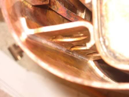 So I set about soldering the rivet stays on the firebox side. The tubeplate end went well but it was when soldering one side that disaster struck. I didn't clamp the firebox to the outer wrapper/barrel and didn't have the end tubeplate supporting the far end of the tubes at the end of the barrel. With the boiler on its side, the heat undid the crown stay joints and the weight of the tubes pulled the firebox crooked so the holes for the rivets on the other side no longer alligned. Luckily I've managed to straighten it but had to apply so much heat it's made a mess of the crown stay joints and I had to re-do these with more flux and solder. The barrel/outer wrapper joint has also suffered. Hopefully I'll be able to re-flow that too. This is how it's looking now. Still hoping it's not an expensive mistake. 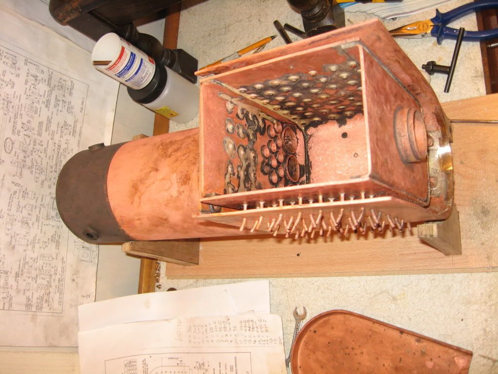 You can see where all the solder ran out of the crown stay joints and formed a lump at the end of the wrapper that I've had to grind away. Other than that I made a start on the chimney having decided to fabricate from 3 pieces of metal. Wide steel round for the base, medium for the main length and brass for the top. I never realised what a challenge this would be - it pushed my lathe to the limit. This is how I cut the 6" radius in the base where it joint the smokebox - talk about minimising the overhang! 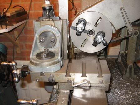 And another photo of the base being set to have the mounting holes drilled. 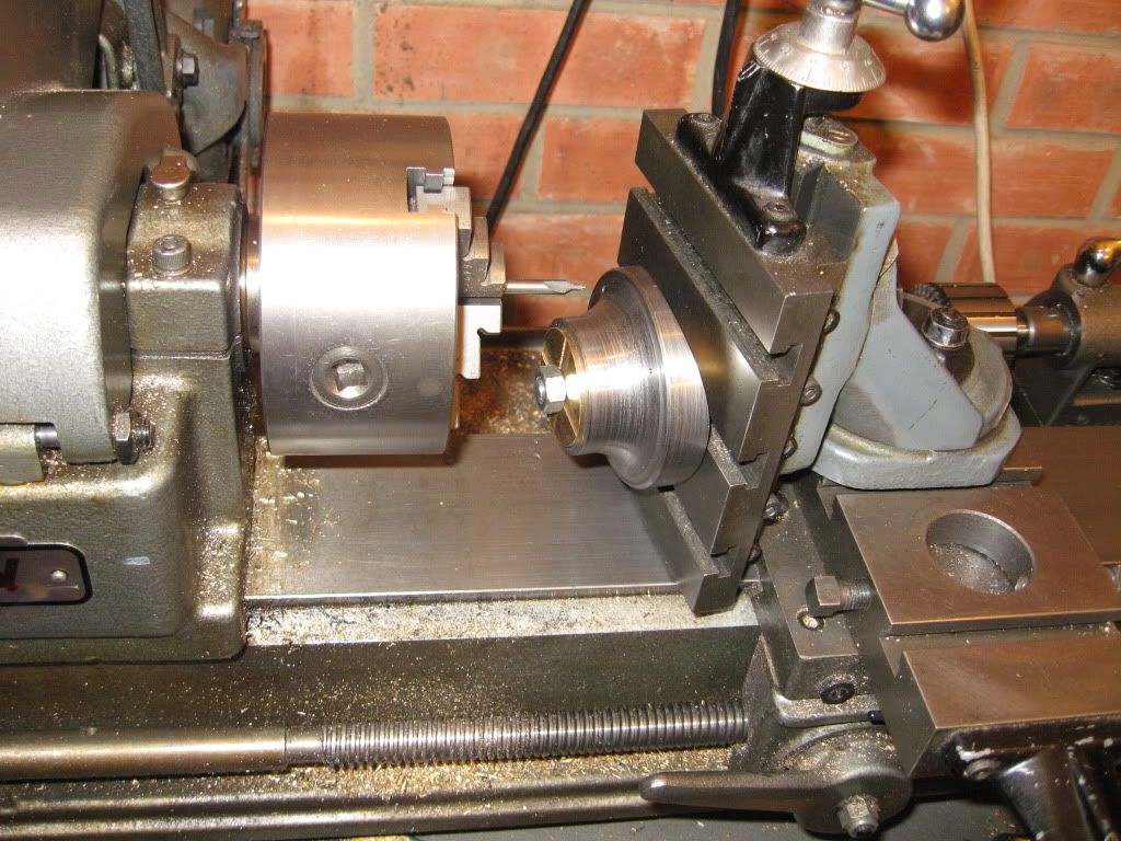 Regards Tim |
|
|
|
Post by Nigel Bennett on Mar 29, 2010 12:10:00 GMT
As others have said, well done for tackling it on an ML10, Tim! I've always liked the look of Jessie and Bridget, but they're just a bit big for me to cart about. Has anybody built one in 5" gauge?
I have to say that Ken Swan's drawings are a model of clarity- I don't think I've come across any as good.
If all model engineering drawings were as good as that, we wouldn't have much to complain about.
|
|
redmog
Part of the e-furniture
 Not Morgan weather
Posts: 461 
|
Post by redmog on Mar 29, 2010 13:48:40 GMT
To Rivet or Not to Rivet. The two halves were soldered together with easyflo. I wasn't looking forward to this but it turned out easy and was pleased with the result. Regards Tim Tim - I've been following your boiler progress with interest, because we are at parallel stages in the boiler making. I'm also at the stage ready to 'stick' the two parts together. I'm sorry to see 'all did not go to plan'. I've been pondering on whether to rivet the girder crownstays to the outer wrapper before soldering as they are fiddly to get at, at the front end, but you've made my mind up. I have nothing to loose by trying to get a couple of rivets in, other than a little skin off my fingers. Presumably you did not rivet the girder stays to the outer wrapper? I also intend to fit the foundation ring, without the rear section, at the same time. Comments welcome, but please put them in my Greasly V4 thread, It would be rude of me to hijack this tread. Chris.
|
|