|
|
Post by Jim on Feb 5, 2014 10:33:52 GMT
Amazing weather we have here in OZ ..40C yesterday and 21C today so I took the opportunity to get into the workshop and complete the tender brake blocks. Apart from cleaning up the castings the job involved slotting each brake block to accept the brake hangers, a job I did with a 1/8" slitting saw. The 'stick' of brake blocks are mounted on a wooden block to reduce the harmonic vibrations and keep the domestic peace  Tomorrow I'll make up the hangers, another job for the mill along with some filing buttons for rounding the ends and central pivot. 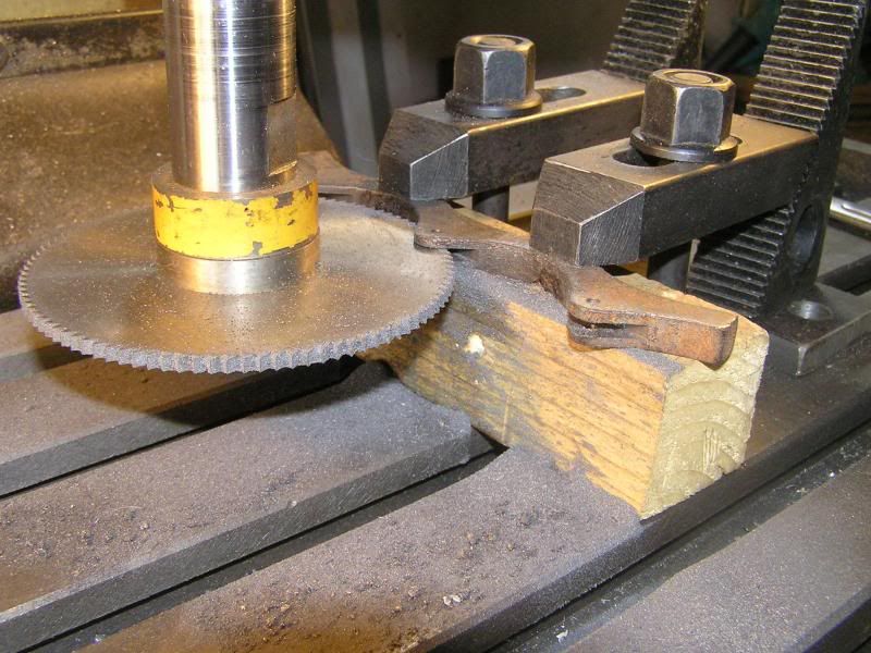 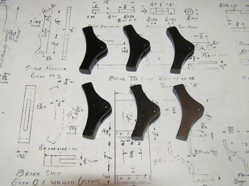 Jim |
|
|
|
Post by Jim on Feb 12, 2014 2:21:25 GMT
Like many of the components on a locomotive, brake hangers and brake shoes are not exactly objects to put on the mantle piece but they are essential and a good project for when it's scorching hot outside. Having completed the shoes the hangers were milled to profile with two appropriately sized rods used to set the tapers between the ends and the centre pivot. 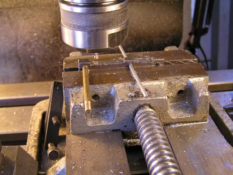 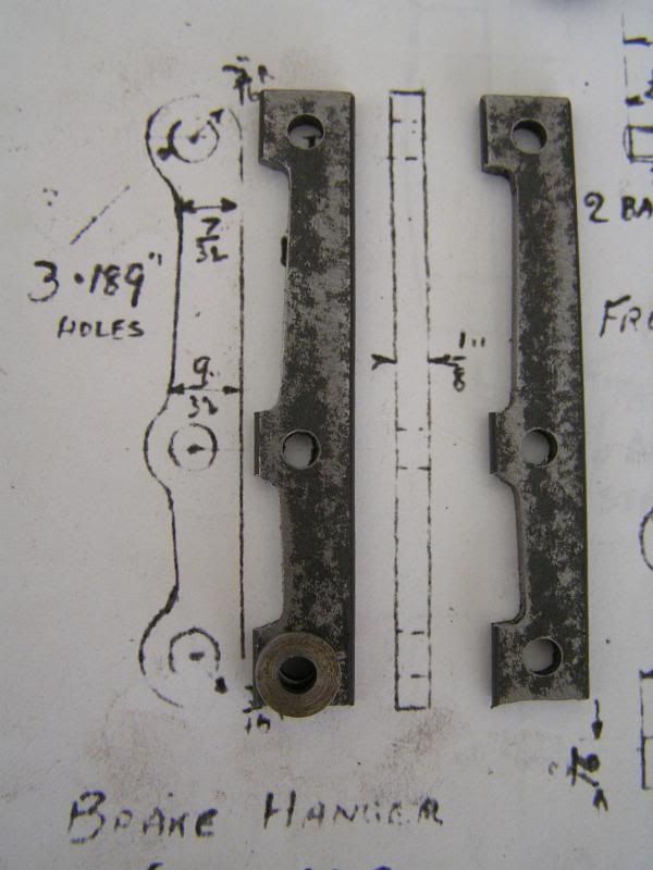 The ends and centre were then filed to profile using time honoured filing buttons, then cleaned up, painted and fitted to their brake shoes. 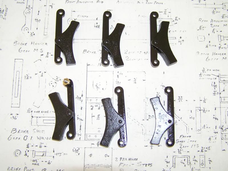 The next job will be to make brake tie bars and rods and actuating mechanism. In between I've been minding our 5 yo grandson who begged me to get my bike out and go for a ride along the bike path with him. After the first 100metres trying to keep up it dawned on me that he was 70 years younger than me. I did manage to make it back home for a restorative soothing ale so I may yet live to complete the boiler.  Jim |
|
|
|
Post by Deleted on Feb 12, 2014 10:39:21 GMT
there sure are lots of parts to these things aren't there Jim?.. seems never ending....btw I wouldn't worry about not being able to keep up with your grandson... I gave up years ago and I'm younger than you so your doing very well...keep him interested in your hobby though... I have done my bit in buying mine a train set and showing him how things work with live steam. Mind you it's my granddaughter who has shown the most interest, at least she's been around the track behind 4470 during trials....  Pete |
|
Geoff
Hi-poster
 
Posts: 171 
|
Post by Geoff on Feb 17, 2014 6:29:44 GMT
Hi Jim,
I found this thread the other day and have read every one of your posts with great interest. Congratulations on what looks to be a fine piece of workmanship, and thank you for making your methods and progress visible to those of us who are still in the very early stages of this continuing learning process.
I am almost at the stage where I can start thinking about building the boiler, and I shall go back through all your posts very carefully, but first, I think I'll follow your method and do some painting. (Anything to delay that fateful moment!!)
Cheers
Geoff
|
|
|
|
Post by Jim on Feb 17, 2014 9:56:43 GMT
Hi Geoff, I'm glad you've found the story of Boadicea's progress helpful, it's a long, continuing but very enjoyable journey. What are you preparing to build, a Britannia?  With regard the boiler as you have probably gathered, I'm no expert, this being my first boiler and to get to the now final stages I've relied heavily on on the advice of others,especially our Club boiler inspector, Barry Potter who has been along the same path many times and is very generous in sharing his knowledge. I'm not sure where you're based but wherever you are you do need to work closely with your boiler inspector to ensure your work is complaint with the relevant boiler codes plus the advice you get will be invaluable. All the best Jim |
|
|
|
Post by Roger on Feb 18, 2014 14:54:04 GMT
Like many of the components on a locomotive, brake hangers and brake shoes are not exactly objects to put on the mantle piece but they are essential and a good project for when it's scorching hot outside. Having completed the shoes the hangers were milled to profile with two appropriately sized rods used to set the tapers between the ends and the centre pivot. The ends and centre were then filed to profile using time honoured filing buttons, then cleaned up, painted and fitted to their brake shoe The next job will be to make brake tie bars and rods and actuating mechanism. In between I've been minding our 5 yo grandson who begged me to get my bike out and go for a ride along the bike path with him. After the first 100metres trying to keep up it dawned on me that he was 70 years younger than me. I did manage to make it back home for a restorative soothing ale so I may yet live to complete the boiler.  Jim I love the lateral thinking in setups like that with the different sized rods, what a simple but effective idea. One thing I tend to do for that sort of setup is to set the work dead level with the end of the jaw by resting a piece of HSS tool steel against the outside of the vice jaw. It just speeds things up when you have loads of the same operation to do. Even without a DRO, you can jot down the position of the graduations at either extreme and just go straight to those. Roger |
|
|
|
Post by Jim on Feb 18, 2014 21:26:41 GMT
Thanks Roger,
Just a suggestion, when you click 'Quote' you can edit it before posting in your reply so that you don't include all the photos that are already there in the previous post. I include too many photos anyway to make up for not doing much.
Jim.
|
|
|
|
Post by Roger on Feb 18, 2014 22:07:05 GMT
Thanks Roger, Just a suggestion, when you click 'Quote' you can edit it before posting in your reply so that you don't include all the photos that are already there in the previous post. I include too many photos anyway to make up for not doing much. Jim. No problem, I've just edited that one and chopped the photos.... much cleaner! |
|
|
|
Post by Jim on Mar 13, 2014 7:51:09 GMT
Activity on Boadicea has been moving at a snail's pace of late due to grandparent duties but slowly things are starting to pick up with work on Boadicea's tender. To date the draw bar and pocket have been completed and today work started on fabricating the mouth of the pocket with its solid rubbing pieces. The first photo shows the rubbing pads silvered in place. The block of brass was used to hold all in place while heating and to stop the parts floating as the silver flowed. 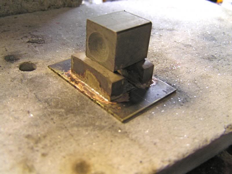 The second photo shows the mouth of the pocket temporarily in place to check size and alignment. The next job will be to add the reinforcing webs to the sides along with drilling the holes for the securing rivets. 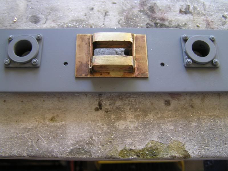 . J Perrier wasn't a draftsman which makes his drawings a challenge and a half to follow and interpret. For example the tender details start at sheet 15 yet when you look for draw bar details you have to go back to sheet 4 "Connecting & Coupling Rod Details" to find the tender draw bar and securing pin tucked away in the bottom right hand corner. There are now newer and properly drafted drawings available, some have been serialized in the model engineering mags but it can be fun trying to find where JP hid things.  On other matters, looking at Julian's photos of his very nice boiler progressing reminds me that I have a very heavy copper object waiting for the final parts to be added. I had hoped it would all self silver in the heat wave but no..another Fail.  Jim |
|
|
|
Post by Shawki Shlemon on Mar 13, 2014 8:30:44 GMT
Any progress is a step forward , well done , just an idea , when I am silver soldering a large surface , I make scratches using hacksaw in all direction , not deep , these allow the silver to easily flow all the way quickly .
|
|
|
|
Post by Jim on Mar 14, 2014 9:02:18 GMT
Thanks Shawki that is good advice re scoring the face to be silver soldered. I must admit it is something I do especially in a case like this. Today the fillets were added and waste backing plate removed and after a final clean up a coat of primer was applied. I like to prime work as I go as apart from protecting the metal it also shows up any imperfections that need touching up or correcting. Looking at the photo I've just spotted a couple of things I want to fix that weren't apparent when I had it on the work bench. I'll get them sorted tomorrow before riveting the plate in its final location on the buffer beam. Jim. 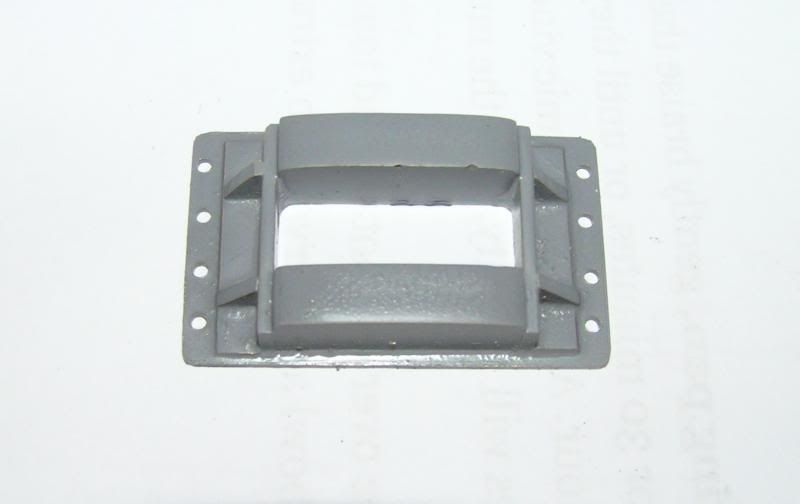 |
|
|
|
Post by Jim on Mar 15, 2014 3:54:31 GMT
The two pictures show the completed tender buffer beam and drag box rubbing blocks which I completed today. I've included the second photo to show a glimpse of the strong back that will take the load when eventually Boadicea is in steam and hauling me round the club track. Progress is slow at present due to other matters but still enjoyable and as always, great relaxation. Jim 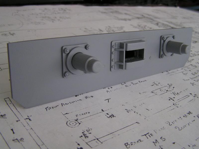 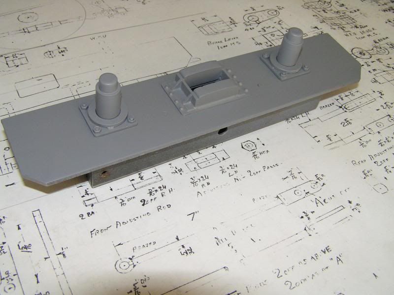 |
|
|
|
Post by runner42 on Mar 15, 2014 6:12:05 GMT
Hi Jim,
your paint finish is magnificent as is your workmanship. I think you should conduct a Master Class on painting a locomotive.
Brian
|
|
|
|
Post by Jim on Mar 15, 2014 6:32:11 GMT
Thank you Brian I'd love to take you up om your suggestion but I think I'd get run out of town when 'they' saw me with a spray can of Duplo Grey Primer in my hand happily spraying the job plus anything else in range.  Seriously though I find the grey primer a good base for the final coat plus as with 'works grey' it does tend to show up anything that's not quite right. You get a similar result when you hold a component up to view it in a mirror. I believe artists used to do that in times past. Jim. |
|
|
|
Post by Geoff (Carlisle) on Mar 15, 2014 21:35:18 GMT
I'll second what Brian said, more so your smokebox it's brilliant.
Geoff (Carlisle).
|
|
|
|
Post by Jim on Mar 22, 2014 7:40:12 GMT
There's not a lot of progress to show on Boadicea at present. The front buffer beam and rubbing plate is now complete and fitted to the tender so I've decided to move on to the tender brake system. It's not very exciting stuff but it is all part and parcel of the model though as with a lot components it will be lost to sight when completed. The first photo shows the first brake rod clevis being cut using a 1/8th slitting saw and a good pair of ear muffs  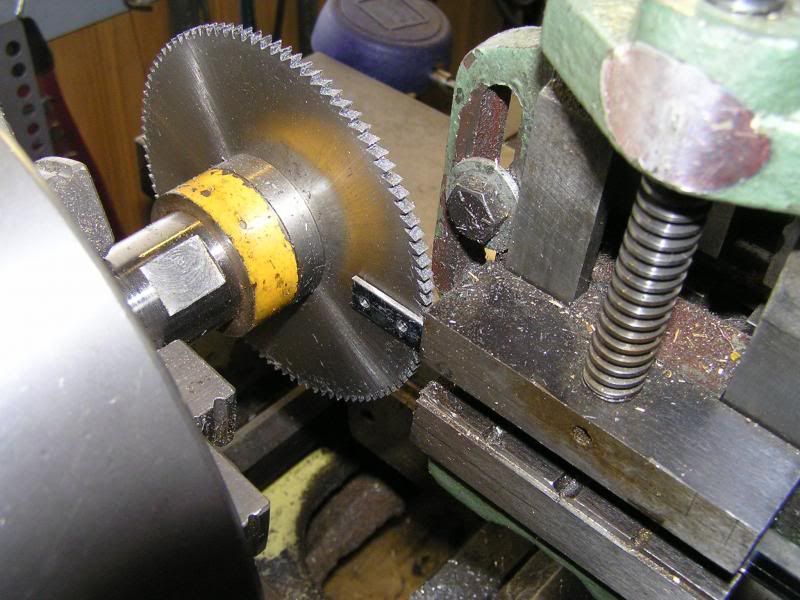 The next photo shows the clevis fitted to the tie beam. The pull rod is threaded 7BA into the 4BA screw in the clevis to form a fine adjuster for when the brakes are finally set up. 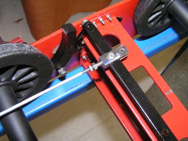 Jim. |
|
|
|
Post by Jim on Apr 6, 2014 0:39:53 GMT
Sadly not a lot of progress being made on Boadicea at the moment still every little bit counts towards the day the first fire is lit, or so they say. The photo shows the tender drag beam assembly completed with what I call the 'dust plate' now in place. At present I'm busily consulting Geoff's photos and plans to clarify the faded parts of my drawings that should show how the tender body is attached to the under frames. I think I have it sorted but it is another 'bump in the road'  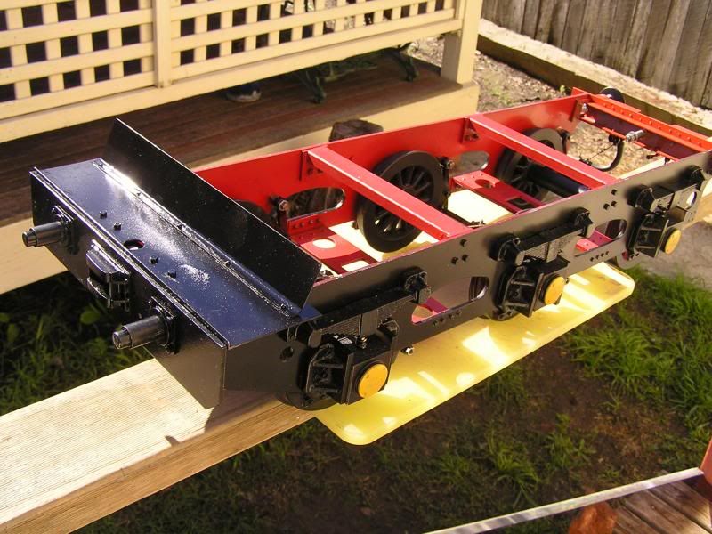 In the meantime I haven't forgotten the boiler  , just organizing the heating  . I see that the Turboset 200 with disposable 400gm oxy/gas bottles are now available here. It will be interesting to see what they are like, price wise they are very attractive once you've bought the initial rig. Interesting. Still staggering on, soothing ale in hand. Jim |
|
|
|
Post by runner42 on Apr 6, 2014 7:12:59 GMT
Hi Jim still watching with interest, keep up the good work.
I have a similar problem with fixing my Doris' tender body to the chassis. There are six holes that are in brass angles in the centre of the chassis for fixing the soleplate to the chassis. If the soleplate was separate from the rest of the body it would be a doddle but with the body closed up one has to try to get the screws and nuts in position from the back cover. You need very small hands to do it and then make them waterproof.
Brian
|
|
|
|
Post by Deleted on Apr 6, 2014 7:46:43 GMT
Why not soft solder some brass studs into the bottom of the soleplate and just use nuts to hold it to the angles? Or you could soft solder some threaded bushes into the soleplate and use screws. If the soleplate is thick enough you could just tap that. It would make assembly/disassembly a lot easier.
John
|
|
|
|
Post by Jim on Apr 6, 2014 11:39:10 GMT
Thank you John for that suggestion I shall look closely into that because it could be applied to Boadicea's tender as well and as you say it would make disassembly much easier if needed.
Jim.
|
|