|
|
Post by runner42 on Aug 5, 2014 8:17:33 GMT
Hi Jim,
I was looking at your boiler design with the aim of seeing what changes I can make to replace the girder type crown stays with number and size of rod stays to meet the AMBSC Code Part 1 requirements. The Belpaire firebox is a diffulcult area to ensure that you get adequate staying and not interfere with such things as the regulator. I was therefore suprised when you have a set of stays straight down the centre which is the area often occupied by the regulator. Your regulator is obviously of a type which is not central. I was therefore interested to know where its positioned and how it operates.
Brian
|
|
|
|
Post by ejparrott on Aug 5, 2014 10:04:55 GMT
Britannia's regulator isn't the same as most locos, it's mounted in the smokebox and the operating rod passes down the outside of the boiler to it. Biggest problem with miniatures is making the rods strong enough so they don't bend instead of operating the valve. Stainless is pretty much a given for this job just to cure that problem
|
|
|
|
Post by Jim on Aug 5, 2014 10:14:09 GMT
To add to Ed's comment I've heard of some modellers running the actual working and heavier regulator rod through a tube in the boiler with the lighter scale non working rods outside as per the original. I'll be doing as Ed suggests.
Jim.
|
|
|
|
Post by Shawki Shlemon on Aug 6, 2014 8:15:09 GMT
C38 & C36 , are the same , just make sure that the rod /rods (if there is a crank in the system ) are well supported along the way .
|
|
|
|
Post by standardsteam on Aug 6, 2014 11:58:03 GMT
Even the full-size Brits were retro-fitted with regulator rod supports... might be a nice thing to replicate on a model?
|
|
|
|
Post by Jim on Aug 6, 2014 12:05:12 GMT
Hi standardsteam,
Thanks for that information I must check it out, have a fair bit of info on the Britannias but had up till now given much thought to mods to the regulator roding.
Jim.
|
|
Andrew C
Part of the e-furniture

Posts: 447
|
Post by Andrew C on Aug 6, 2014 17:10:57 GMT
Hi Jim There are two supports that were retro fitted. The first is half way along the firebox cladding. The second half way between the regulator and the crank. Page 11 of locomotives in detail. By David Clark. Glad to see we have progress again Jim  |
|
|
|
Post by ejparrott on Aug 7, 2014 9:49:04 GMT
Learn something new every day! Easy to see why they did it though. I wonder if the fullsize had similar issues to the miniatures?
|
|
|
|
Post by standardsteam on Aug 7, 2014 10:24:56 GMT
|
|
Tony K
Elder Statesman
  
Posts: 1,574
|
Post by Tony K on Aug 7, 2014 12:13:54 GMT
Jim, what type of regulator are you planning to use - as the Perrier drawings or something different e.g. gas valve?
Perhaps this is obvious if I look back through in more detail, but I cannot see it at the moment.
|
|
|
|
Post by Jim on Aug 7, 2014 13:31:11 GMT
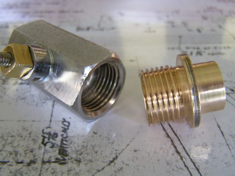
Yes Tony I used a gas tap but the type I used had a screw in bronze retaining collar for the PTFE bushes which allows you to easily adjust them if they are too tight when hot or if at some stage they need replacing. Many of the taps are press fitted and so any adjustment is much harder. Gas valves are used a lot here and with good results. You may need to look at the space available in the smoke box as the gas valve comes forward a lot further than JP's poppet valve regulator. The photo shows the valve and the bush that will be brazed into the front tube plate.  Jim |
|
|
|
Post by Geoff (Carlisle) on Aug 7, 2014 21:52:14 GMT
Hi Jim, when it comes to regulators,I will be making mine as Martin Evans Springbok type ( Disc in a tube), transversely mounted.Nobody has had any trouble with this type of regulator, and it will be spot on.
Geoff (Carlisle).
|
|
jma1009
Elder Statesman
  
Posts: 5,922
|
Post by jma1009 on Aug 7, 2014 23:36:24 GMT
i am very interested in Jim's regulator valve which im sure will prove excellent plus leak free on hydraulic tests.
unfortunately for smaller locos the commercial fittings of this type are a bit too big.
the late Roy Amesbury built a superb Brit in 3.5"g with proper poppet valve regulator. i am not too sure how Geoff will arrange a disc in tube regulator for his excellent Clan - perhaps we can get him to re-think?! (i know martin evans did a push pull type regulator of disc in tube type, but dont recall very favourable comments of it's operation).
incidentally Geoff, how are you getting on with the Clan in our unseemly hot summer?
i am very much looking forward to the completion of Jim's Brit boiler which cant be far off now!! plus the first steaming!!
cheers,
julian
|
|
|
|
Post by Jim on Aug 8, 2014 1:07:47 GMT
Hi Jim There are two supports that were retro fitted. The first is half way along the firebox cladding. The second half way between the regulator and the crank. Page 11 of locomotives in detail. By David Clark. Glad to see we have progress again Jim  Thanks for that heads up Andrew. I have Clark's book and will check out the page. It's a funny thing, you think you have checked out all possible variations until very fortunately, someone such as yourself comes up with information previously overlooked. Thanks again for the 'heads up' Thanks too Geoff and Julian for your comments and observations. The boiler is nearly completed Julian with me currently working on fitting the 2 remaining sides of the foundation ring plus filling in the corners. The photos you've posted along with a link Geoff provided to a boiler making series of photos on Geoff's Club site have proved invaluable in providing sensible and practical information on a task that is often made out by some as being akin to building space rocket and not at all encouraging. Sadly I now have a ton of firewood to stack so a retreat to the workshop is out of the question for a while, a soothing ale won't be though.  Jim |
|
|
|
Post by Jim on Aug 8, 2014 3:51:59 GMT
That's a brilliant link thank you very much indeed. Jim |
|
|
|
Post by Geoff (Carlisle) on Aug 8, 2014 21:15:14 GMT
Hi Jim & Julian, the drawings for the disc in a tube appeared in the Model Engineer, 15th sept 1960. If you think about it, where the regulator rod goes into the smokebox it goes straight into the valve and you can adjust it from the top with the cover off. But the Clan is on hold at the moment until i get the Gresley V3 rebuilt,I'm trying to sort out all the pipes, you wouldn't believe it but i built it in the first place, put an extra log on the fire Jim and keep warm, with a soothing ale.
Geoff (Carlisle).
|
|
Andrew C
Part of the e-furniture

Posts: 447
|
Post by Andrew C on Aug 8, 2014 21:21:26 GMT
That's a brilliant link thank you very much indeed. Jim This link is probably the best and most complete list of the mods on the net if not in print. Thanks for reminding us all. Andrew |
|
|
|
Post by Jim on Aug 8, 2014 22:17:40 GMT
Hi Jim & Julian, the drawings for the disc in a tube appeared in the Model Engineer, 15th sept 1960. If you think about it, where the regulator rod goes into the smokebox it goes straight into the valve and you can adjust it from the top with the cover off. But the Clan is on hold at the moment until i get the Gresley V3 rebuilt,I'm trying to sort out all the pipes, you wouldn't believe it but i built it in the first place, put an extra log on the fire Jim and keep warm, with a soothing ale. Geoff (Carlisle). I'll be interested in seeing the set up you're using Geoff for the transverse mounted 'disc in tube' regulator. I have the design for the standard straight version in Martin Evens' book. As has been said before there are many ways to get the same end result. I was going to say 'many ways of skinning a cat' till I saw the look in our cat's eye. She can be quite vindictive, knocking small parts under hard to get at places, when upset.  Today the back is telling me, 'no more stacking fire wood lad!' so i can get on with the sides of the foundation ring. Jim |
|
Tony K
Elder Statesman
  
Posts: 1,574
|
Post by Tony K on Aug 9, 2014 8:32:24 GMT
Jim, while we are talking regulators - for collecting the steam for the regulator, the drawings show a horizontal tube with holes in the top which has an end spacer secured by a screw from the top of the boiler. There is nothing going into the dome.
Are you thinking of using this arrangement or something protruding into the dome which, being higher, could reduce the chance of collecting water?
Again, apologies for naivety and possible repetition.
|
|
|
|
Post by Jim on Aug 9, 2014 12:31:58 GMT
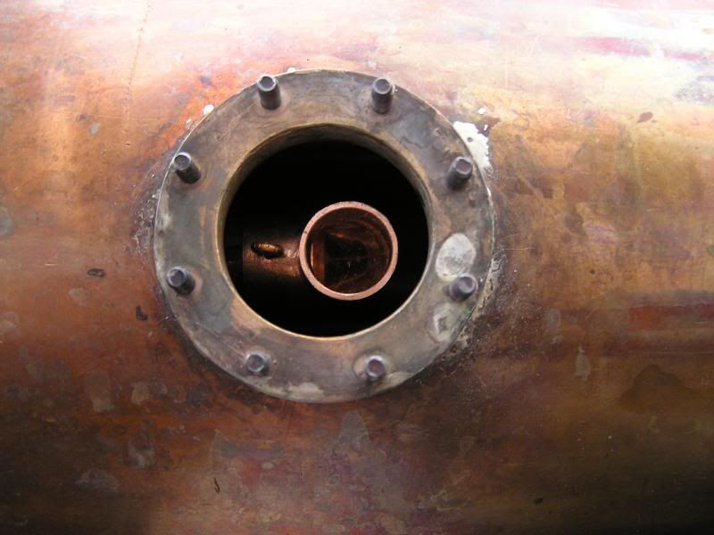
No need for any apologies Tony. In answer to your question Perrier's straight steam collection tube with its many holes along the upper surface seemed guaranteed to ingest water at every possible opportunity so I opted for a simple tube with a standard plumbing copper right angled elbow positioned to sit just below the dome cover. To stop the elbow rotating I cross drilled it and fitted a long pin made from copper wire. In the photo you can see the formed ring on the end of the pin which because of its length can't come out unless the dome cover is removed.  Jim |
|